Table of Contents
Advertisement
Copyright
This publication, including all photographs, illustrations and software, is protected
under international copyright laws, with all rights reserved. Neither this manual, nor
any of the material contained herein, may be reproduced without written consent of
the author.
Version 1.0
Disclaimer
The information in this document is subject to change without notice. The manufac-
turer makes no representations or warranties with respect to the contents hereof
and specifically disclaims any implied warranties of merchantability or fitness for
any particular purpose. The manufacturer reserves the right to revise this publica-
tion and to make changes from time to time in the content hereof without obligation
of the manufacturer to notify any person of such revision or changes.
Trademark Recognition
Microsoft, MS-DOS and Windows are registered trademarks of Microsoft Corp.
MMX, Pentium, Pentium-II, Pentium-III, Celeron are registered trademarks of Intel
Corporation.
Other product names used in this manual are the properties of their respective owners
and are acknowledged.
Federal Communications Commission (FCC)
This equipment has been tested and found to comply with the limits for a Class B
digital device, pursuant to Part 15 of the FCC Rules. These limits are designed to
provide reasonable protection against harmful interference in a residential instal-
lation. This equipment generates, uses, and can radiate radio frequency energy and,
if not installed and used in accordance with the instructions, may cause harmful
interference to radio communications. However, there is no guarantee that interfer-
ence will not occur in a particular installation. If this equipment does cause harmful
interference to radio or television reception, which can be determined by turning
the equipment off and on, the user is encouraged to try to correct the interference by
one or more of the following measures:
•
Reorient or relocate the receiving antenna
•
Increase the separation between the equipment and the receiver
•
Connect the equipment onto an outlet on a circuit different from that to
which the receiver is connected
•
Consult the dealer or an experienced radio/TV technician for help
Shielded interconnect cables and a shielded AC power cable must be employed with
this equipment to ensure compliance with the pertinent RF emission limits govern-
ing this device. Changes or modifications not expressly approved by the system's
manufacturer could void the user's authority to operate the equipment.
H61H2-TI USER MANUAL
Preface
Advertisement
Table of Contents

Subscribe to Our Youtube Channel
Related Manuals for ECS H61H2-TI


Summary of Contents for ECS H61H2-TI
- Page 1 Preface Copyright This publication, including all photographs, illustrations and software, is protected under international copyright laws, with all rights reserved. Neither this manual, nor any of the material contained herein, may be reproduced without written consent of the author. Version 1.0 Disclaimer The information in this document is subject to change without notice.
-
Page 2: Declaration Of Conformity
Declaration of Conformity This device complies with part 15 of the FCC rules. Operation is subject to the follow- ing conditions: • This device may not cause harmful interference. • This device must accept any interference received, including interference that may cause undesired operation. This device is in conformity with the following EC/EMC directives: ... -
Page 3: Table Of Contents
TABLE OF CONTENTS Preface Chapter 1 Introducing the Motherboard Introduction...................1 Pakage Contents................1 Specifications................2 Motherboard Components............4 I/O Ports....................6 Chapter 2 Installing the Motherboard Safety Precautions................7 Installing the Motherboard in a Chassis........7 Checking Jumper Settings............8 Installing Hardware..............10 Installing the Processor............10 Installing the CPU Cooler............12 Installing Memory Modules............13 Installing Add-on Cards............14 Connecting Optional Devices..........16... - Page 4 Chapter 4 Using the Motherboard Software Auto-installing under Windows XP/7/8........55 ..Running Setup..............55 Manual Installation................57 Chapter 5 Trouble Shooting Start up problems during assembly..........59 Start up problems after prolong use..........60 Maintenance and care tips..............60 Basic Troubleshooting Flowchart...........61 H61H2-TI USER MANUAL...
-
Page 5: Introducing The Motherboard
Chapter 1 Introducing the Motherboard Introduction Thank you for choosing the H61H2-TI motherboard. This motherboard is a high performance, enhanced function motherboard designed to support the LGA1155 ® ® ® socket for latest Intel Core Family/Pentium /Celeron Processors* for high-end business or personal desktop markets. -
Page 6: Specifications
Specifications ® ® • LGA1155 socket for latest Intel Core Family/Pentium ® Celeron Processors ® Chipset • Intel H61 Chipset Extra Chips • Asmedia ASM1042 supports two USB 3.0 ports Memory • Dual-channel DDR3 memory architecture • 2 x 204-pin DDR3 SO-DIMM sockets support up to 16 GB •... - Page 7 • 1 x LCD panel backlight control (optional) • 1 x LCD select jumper (optional) • 1 x LVDS connetor (optional) • 1 x LCD mode select header (optional) System BIOS • AMI BIOS with 64Mb SPI Flash ROM - Supports Plug and Play - Supports ACPI &...
-
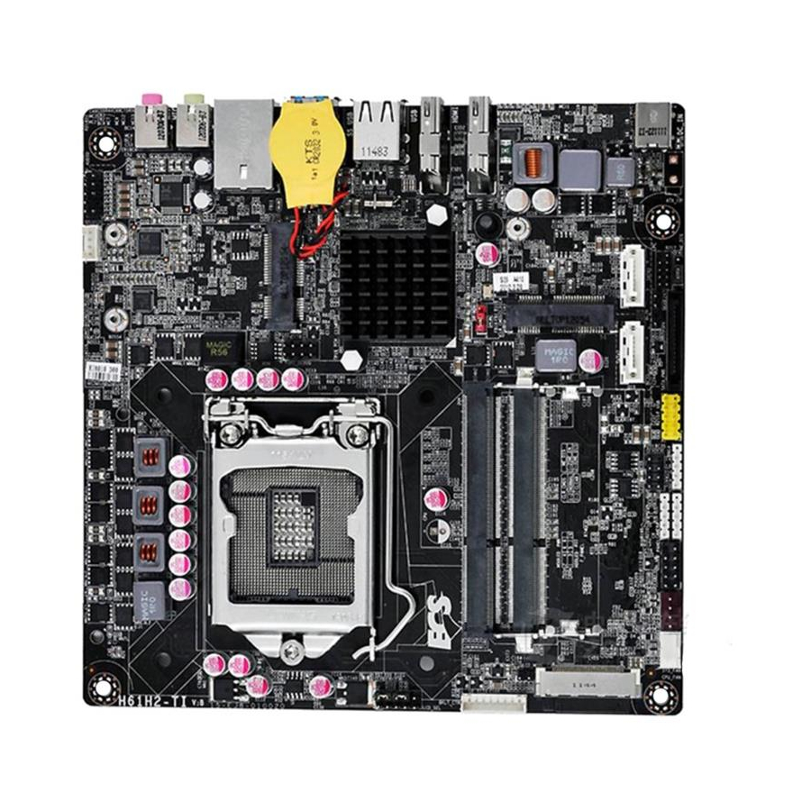
Page 8: Motherboard Components
Motherboard Components H61H2-TI USER MANUAL... - Page 9 Table of Motherboard Components LABEL COMPONENTS LGA1155 socket for latest Intel® Core Family/ 1. CPU Socket Pentium®/Celeron® Processors 2. DMIC Digital microphone header (optional) 3. SPEAKER 2 Channels audio speaker header (optional) 4. F_AUDIO Front panel audio header 5. PCIE2 Mini PCI Express x 1 slot (supports full-card and you can install a Mini SATA (mSATA) card into it) 6.
-
Page 10: I/O Ports
I/O Ports 1. DC_IN Port Connect the DC_IN port to the power adapter. 2. HDMI_IN Port (optional) You can connect the HDMI output of other computer or other HDMI source to the HDMI_IN port. HDMI_IN port LCD_MODE button pulse Power ON Un-plugged LCD off ... -
Page 11: Installing The Motherboard
Chapter 2 Installing the Motherboard 2-1. Safety Precautions Follow these safety precautions when installing the motherboard: • Wear a grounding strap attached to a grounded device to avoid damage from static electricity. • Discharge static electricity by touching the metal case of a safely grounded object before working on the motherboard. -
Page 12: Checking Jumper Settings
2-3. Checking Jumper Settings This section explains how to set jumpers for correct configuration of the motherboard. Components LCD_SEL CLR_CMOS ME_DIS 1. LCD_SEL: LCD select jumper (optional) 1.When your panel connects to LVDS, please check LCD Select header setting first. 2.Due to the differences of the panel parameters, please follow the above illustration to place the jumper caps. - Page 13 2. CLR_CMOS: Clear CMOS jumper The following illustration shows the location of the motherboard jumpers. Pin 1 is labeled. To avoid the system instability after clearing CMOS, we recommend users to enter the main BIOS setting page to “Load Default Settings” and then “Save and Exit Setup”.
-
Page 14: Installing Hardware
2-4. Installing Hardware 2-4-1. Installing the Processor • This motherboard has an LGA1155 socket. • When choosing a processor, consider the performance requirements of the system. Performance is based on the processor design, the clock speed and system bus frequency of the processor, and the quantity of internal cache memory and external cache memory. - Page 15 D. Rotate the load plate onto the package IHS (Intergraded Heat Spreader). Engage the load lever while pressing down lightly onto the load plate. Secure the load lever with the hook under retention tab. Then the cover will flick automatically. Please save and replace the cover onto the CPU socket if processor is re- moved.
-
Page 16: Installing The Cpu Cooler
2-4-2. Installing the CPU Cooler • Install the cooling fan in a well-lit work area so that you can clearly see the motherboard and processor socket. • Avoid using cooling fans with sharp edges in case the fan casing and the clips cause serious damage to the motherboard or its components. -
Page 17: Installing Memory Modules
2-4-3. Installing Memory Modules • This motherboard accommodates two memory modules. It can support two 204-pin DDR3 1333/1066. • Do not remove any memory module from its antistatic packaging until you are ready to install it on the motherboard. Handle the modules only by their edges. -
Page 18: Installing Add-On Cards
2-4-4. Installing Add-on Cards The slots on this motherboard are designed to hold expansion cards and connect them to the system bus. Expansion slots are a means of adding or enhancing the motherboard’s features and capabilities. With these efficient facilities, you can increase the motherboard’s capabilities by adding hardware that performs tasks that are not part of the basic system. - Page 19 Follow these instructions to install a wireless card: Remove a blanking plate from the system case, and insert the wireless card into the MINIPCIE slot rightwards, then tighten the two screws (Please refer to Picture 1). Press the metal connector of the cable into the connector on the wireless card.
-
Page 20: Connecting Optional Devices
2-4-5. Connecting Optional Devices Refer to the following for information on connecting the motherboard’s optional devices: Components Components F_USB DMIC TOUCH F_AUDIO CAMERA CASE SATA1~2 LVDS LCD_MODE SATA_PWR BKLT_CTRL —— —— H61H2-TI USER MANUAL... - Page 21 1. F_USB: Front Panel USB 2.0 header The motherboard has one USB 2.0 headers supporting two USB 2.0 ports. Addition- ally, some computer cases have USB 2.0 ports at the front of the case. If you have this kind of case, use auxiliary USB 2.0 connector to connect the front-mounted ports to the motherboard.
- Page 22 5. CIR: Consumer infrared 6. LVDS: LVDS connector (optional) 1. You can connect the large end of the cable to the LED Panel, and connect the other small end to the slot on the motherboard. 2.Due to the chipset limitation, using dual displays LVDS(AIO) + VGA or LVDS(AIO) + HDMI will cause the problem that you may not enter BIOS setup or have the display problem.
- Page 23 7. LCD_MODE: LCD mode select header (optional) When you press this button, the LCD display will switch by the turns of AIO/ HDMI/LCD OFF. 8. BKLT_CTRL: LCD panel backlight control (optional) H61H2-TI USER MANUAL...
- Page 24 9. DMIC: Digital microphone header (optional) 10. F_AUDIO: Front Panel Audio Header The front panel audio header allows the user to install auxiliary front-oriented mi- crophone and line-out ports for easier access. This header supports HD audio by default. If you want connect an AC’...
- Page 25 AC’ 97 Audio Configuration: To enable the front panel audio connector to support AC97 Audio mode. If you use AC’ 97 Front Panel, please tick off the option of “ Disabled Front Panel Detect ”. If you use HD Audio Front Panel, please don’...
- Page 26 12. SATA1~2: Serial ATA II connectors SATA1~2 connectors are used to support the Serial ATA 3Gb/s device. Simpler disk drive cabling and easier PC assembly. It eliminates limitations of the current Paral- lel ATA interface. But maintains register compatibility and software compatibility with Parallel ATA.
- Page 27 14. LPC: Low pin count header 15. SATA_PWR: SATA power connector H61H2-TI USER MANUAL...
-
Page 28: Installing A Hard Disk Drive/Optical Disk Drive
2-4-6. Installing a Hard Disk Drive/Optical Disk Drive This section describes how to install a Hard Disk Drive/Optical Disk Drive. About SATA Connectors Your motherboard features two SATA connectors supporting a total of two drives. SATA refers to Serial ATA (Advanced Technology Attachment) is the standard inter- face for the IDE hard drives which are currently used in most PCs. - Page 29 About mSATA Connectors Your motherboard features two Mini PCI Express x1 slots, the PCIE2 supports full- card, you can install a Mini SATA (mSATA) card into it. Refer to the illustration below for proper installation: Insert a Mini SATA (mSATA) card into the PCIE2 Slot. Lower the handle and tighten the screws.
-
Page 30: Connecting Case Components
2-4-7. Connecting Case Components After you have installed the motherboard into a case, you can begin connecting the motherboard components. Refer to the following: Components F_PANEL SYS_FAN CPU_FAN SPEAKER H61H2-TI USER MANUAL... - Page 31 1. F_PANEL: Front Panel Header The front panel header (F_PANEL) provides a standard set of switch and LED headers commonly found on ATX or Micro ATX cases. Refer to the table below for information: Hard Drive Activity LED Connecting pins 1 and 3 to a front panel mounted LED provides visual indication that data is being read from or written to the hard drive.
- Page 32 2 & 3 . SYS_FAN (System Cooling FAN Power Connector) &CPU_FAN (CPU cool- ing FAN Power Connector) Connect the CPU cooling fan cable to CPU_FAN. Connect the system cooling fan connector to SYS_FAN. Users please note that the fan connector supports the CPU cooling fan of 1.1A ~ 2.2A (26.4W max) at +12V.
-
Page 33: Using Bios
Chapter 3 Using BIOS About the Setup Utility The computer uses the latest “American Megatrends Inc. ” BIOS with support for Windows Plug and Play. The CMOS chip on the motherboard contains the ROM setup instructions for configuring the motherboard BIOS. The BIOS (Basic Input and Output System) Setup Utility displays the system’s con- figuration status and provides you with options to set system parameters. -
Page 34: Resetting The Default Cmos Values
Press the delete key to access BIOS Setup Utility. Above image is for reference only, for details please refer to actual image. Resetting the Default CMOS Values When powering on for the first time, the POST screen may show a “CMOS Settings Wrong”... -
Page 35: Bios Navigation Keys
In this manual, default values are enclosed in parenthesis. Submenu items are denoted by an icon The default BIOS setting for this motherboard apply for most conditions with optimum performance. We do not suggest users change the default values in the BIOS setup and take no responsibility to any damage caused by changing the BIOS settings. -
Page 36: Main Menu
Main Menu This menu shows the information of BIOS and enables you to set the system language, date and time. Main Advanced Chipset Frequency/Voltag Boot Security Exit Choose the system default BIOS Information language System Language English System Date Fri 08/31/2012 System Time 00: 46: 39 : Select Screen... -
Page 37: Advanced Menu
Advanced Menu The Advanced menu items allow you to change the settings for the CPU and other system. Main Advanced Chipset Frequency/Voltag Boot Security Exit Intel(R) Smart Connect LAN Configuration Technology Settings PC Health Status Power Management Setup ACPI Settings CPU Configuration SATA Configuration USB Configuration... -
Page 38: Lan Configuration
LAN Configuration The item in the menu shows the LAN-related information that the BIOS automatically detects. Main Advanced Chipset Frequency/Voltag Boot Security Exit Enabled/Disabled Onboard LAN Configuration LAN 1 Controller Onboard LAN Controller Enabled : Select Screen : Select Item Enter : Select +/- : Change Opt. -
Page 39: Pc Health Status
PC Health Status On motherboards support hardware monitoring, this item lets you monitor the parameters for critical voltages, temperatures and fan speeds. Main Advanced Chipset Frequency/Voltag Boot Security Exit PC Health Status System Temperature 50°C CPU Fan Speed 1251 RPM System Fan Speed 1779 RPM CPU Voltage... -
Page 40: Power Management Setup
Power Management Setup This page sets up some parameters for system power management operation. Main Advanced Chipset Frequency/Voltag Boot Security Exit About Resume by Power Management Setup PCI/PCI-E/LAN/ Ext . USB3.0 PME Resume By PME Disabled Resume By USB(S3) Disabled EUP Function Enabled : Select Screen... -
Page 41: Acpi Configuration
ACPI Configuration The item in the menu shows the highest ACPI sleep state when the system enters suspend. Main Advanced Chipset Frequency/Voltag Boot Security Exit ACPI Settings Select the highest ACPI sleep state the system ACPI Sleep State S3 (Suspend to RAM) will enter when the SUSPEND button is pressed. -
Page 42: Cpu Configuration
CPU Configuration The item in the menu shows the CPU Configuration. Main Advanced Chipset Frequency/Voltag Boot Security Exit CPU Configuration Number of cores to enable in each processor package. Intel(R) Core(TM) I5-3330S CPU @ 2.70GHz 64-bit Supported Processor Speed 2700 MHz Processor Stepping 306a9 Microcode Revision... - Page 43 Excute Disable Bit (Enabled) This item allows the processor to classify areas in memory by where application code can execute and where it cannot. When a malicious worm attempts to insert code in the buffer, the processor disables code execution, preventing damage or worm propagation.
-
Page 44: Sata Configuration
SATA Configuration Use this item to show the mode of serial SATA configuration options. Main Advanced Chipset Frequency/Voltag Boot Security Exit SATA Configuration Determines how SATA controller(s) operate. SATA Mode IDE Mode SATA Port1 WDC WD3200AAJS (320.0GB) SATA Port2 Not Present : Select Screen ... -
Page 45: Usb Configuration
USB Configuration Use this item to show the information of USB configuration. Main Advanced Chipset Frequency/Voltag Boot Security Exit If the USB 3.0 controller USB Configuration is external chip USB 3.0 Controller Enabled Legacy USB Support Enabled : Select Screen ... -
Page 46: Super Io Configuration
Super IO Configuration Use this item to show the information of Super IO configuration. Main Advanced Chipset Frequency/Voltag Boot Security Exit Super IO Configuration Enable or Disable CIR Controller Super IO Chip F71808A CIR Controller Enabled : Select Screen ... -
Page 47: Chipset Menu
Chipset Menu The chipset menu items allow you to change the settings for the North Bridge chipset, South Bridge chipset and other system. Main Advanced Chipset Frequency/Voltag Boot Security Exit System Agent Configuration Configure Management PCH Configuration North Bridge Parameters. Engine Technology Param- ME Configuration eters... -
Page 48: Pch Configuration
PCH Configuration Scroll to this item and press <Enter> to view the following screen: Main Advanced Chipset Frequency/Voltag Boot Security Exit PCH Configuration Select AC Power state when power is re-applied after Restore AC Power Loss Power Off a power failure. Audio Configuration Azalia HD Audio Enabled... - Page 49 ME Configuration Scroll to this item and press <Enter> to view the following screen: Main Advanced Chipset Frequency/Voltag Boot Security Exit Management Engine Technology Configuration ME FW Version 8.1.0.1248 : Select Screen : Select Item Enter : Select +/- : Change Opt.
-
Page 50: Frequency/Voltag Menu
Frequency/Voltag Menu This page enables you to set the clock speed and system bus for your system. The clock speed and system bus are determined by the kind of processor you have installed in your system. Main Advanced Chipset Frequency/Voltag Boot Security Exit... - Page 51 Turbo Mode (Enabled) This item allows you to control the Intel Turbo Boost Technology. Runtime Turbo Enable (Disabled) This item shows if CPU support runtime turbo or not. Over Clocking Extra Vol.(1/256 V) (0) This item allows you to control Extra CPU voltage. 1/2/3/4 Core Ratio Limit (32/31/29/28) These items show the Core Ratio Limit Values.
- Page 52 Chipset OverClocking Configuration Scroll to this item to view the following screen: Main Advanced Chipset Frequency/Voltag Boot Security Exit Memory Timing Cofiguration CAS# Latency(tCL) RAS# to CAS# Delay(tRCD) : Select Screen Row Precharge Time(tRP) : Select Item RAS# Active Time(tRAS) Enter : Select Write Recovery Time(tWR) +/- : Change Opt.
- Page 53 B.O.M.P Technology (Enabled) This item allows users to enable or disable B.O.M.P technology. This function can run safe setting to setup menu when system boot fail 3 times. Auto Detect DIMM/PCI Clk (Enabled) When this item is enabled, BIOS will disable the clock signal of free DIMM/PCI slots. Spread Spectrum (Enabled) If you enable spread spetrum, it can significantly reduce the EMI (Electro-Magnetic Interference) generated by the system.
-
Page 54: Boot Menu
Boot Menu This page enables you to set the keyboard NumLock state. Main Advanced Chipset Frequency/Voltag Boot Security Exit Boot Configuration Windows 7 or other OS: Boot policy for Legacy OS Operation System Select Windows 7 or other OS Launch PXE OpROM Disabled Windows 8: Boot policy for Launch Strorage OpROM... -
Page 55: Security Menu
Security Menu This page enables you to set setup administrator password and user password. Main Advanced Chipset Frequency/Voltag Boot Security Exit Administrator Password Status Not Install Set Administrator Password User Password Status Not Install Administrator Password System Mode state Setup Secure Boot state Disabled : Select Screen... -
Page 56: Exit Menu
Exit Menu This page enables you to exit system setup after saving or without saving the changes. Main Advanced Chipset Frequency/Voltag Boot Security Exit Back to EZ Mode Go back to EZ Mode Save Changes and Exit Discard Changes and Exit Discard Changes and Reset Save Options Save Changes... -
Page 57: Updating The Bios
Updating the BIOS You can download and install updated BIOS for this motherboard from the manufacturer’s Website. New BIOS provides support for new peripherals, improve- ments in performance, or fixes for known bugs. Install new BIOS as follows: If your motherboard has a BIOS protection jumper, change the setting to allow BIOS flashing. -
Page 58: H61H2-Ti User Manual
Memo H61H2-TI USER MANUAL... -
Page 59: Using The Motherboard Software
Chapter 4 Using the Motherboard Software Auto-installing under Windows XP/7/8 The auto-install DVD-ROM makes it easy for you to install the drivers and software. The support software DVD-ROM disc loads automatically under Windows XP/7/8. When you insert the DVD-ROM disc in the DVD-ROM drive, the auto-run feature will automatically bring up the installation screen. - Page 60 Click Next. The following screen appears: Check the box next to the items you want to install. The default options are recommended. Click Next to run the Installation Wizard. An item installation screen appears: Follow the instructions on the screen to install the items. Drivers and software are automatically installed in sequence.
-
Page 61: Manual Installation
Windows 7/8 will appear below UAC (User Account Control) message after the system restart. You must select “Yes” to install the next driver. Continue this process to complete the drivers installation. Manual Installation If the auto-install DVD-ROM does not work on your system, you can still install drivers through the file manager for your OS (for example, Windows Explorer). - Page 62 Memo H61H2-TI USER MANUAL...
-
Page 63: Trouble Shooting
Chapter 5 Trouble Shooting Start up problems during assembly After assembling the PC for the first time you may experience some start up problems. Before calling for technical support or returning for warranty, this chapter may help to address some of the common questions using some basic troubleshooting tips. -
Page 64: Start Up Problems After Prolong Use
Start up problems after prolong use After a prolong period of use your PC may experience start up problems again. This may be caused by breakdown of devices connected to the motherboard such as HDD, CPU fan, etc. The following tips may help to revive the PC or identify the cause of failure. - Page 66 Memo H61H2-TI USER MANUAL...
Need help?
Do you have a question about the H61H2-TI and is the answer not in the manual?
Questions and answers