MTD 551 Operator's Manual
Hide thumbs
Also See for 551:
- Operator's manual (20 pages) ,
- Operator's manual (21 pages) ,
- Operator's manual (20 pages)
Table of Contents
Advertisement
Quick Links
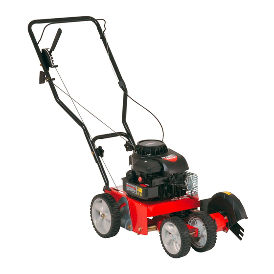
Operator's Manual
Edger
Models 521
550
551
Model 550 and 551 Shown
IMPORTANT:
READ SAFETY
RULES AND INSTRUCTIONS
CAREFULLY
Warning:
This unit is equipped with an internal combustion engine and should not be used on or near any unimproved
forest-
covered, brush-covered
or grass-covered
land unless the engine's exhaust system is equipped with a spark arrester meeting
applicable local or state laws (if any). If a spark arrester is used, it should be maintained in effective working order by the operator.
In the State of California the above is required by law (Section 4442 of the California Public Resources Code). Other states may have
similar laws. Federal laws apply on federal lands. A spark arrester for the muffler is available through your nearest engine authorized
service dealer or contact the service department,
P.O. Box 361131 Cleveland, Ohio 44!36-0019.
MTD LLC, P.O. BOX 361131 CLEVELAND,
OHIO 44136-0019
PRINTED IN U.S.A.
FORM NO. 769-00527B
(5/03)
Advertisement
Table of Contents

Related Manuals for MTD 551


Summary of Contents for MTD 551
- Page 1 Federal laws apply on federal lands. A spark arrester for the muffler is available through your nearest engine authorized service dealer or contact the service department, P.O. Box 361131 Cleveland, Ohio 44!36-0019. MTD LLC, P.O. BOX 361131 CLEVELAND, OHIO 44136-0019 PRINTED IN U.S.A.
-
Page 2: Table Of Contents
The information on the model plate is very important if you need help from the MTD Customer Support Department. You can locate the model number by looking on the surface of the base plate in the rear of the edger. A sample model plate is explained below. -
Page 3: Important Safe Operation Practices
SECTION 1: IMPORTANT SAFEOPERATION P RACTICES WARNING: THIS SYMBOL POINTS OUT IMPORTANT SAFETY INSTRUCTIONS WHICH, IF NOT FOLLOWED, COULD ENDANGER THE PERSONAL SAFETY AND/OR PROPERTY OF YOURSELF AND OTHERS. READ AND FOLLOW ALL INSTRUCTIONS IN THIS MANUAL BEFORE ATTEMPTING TO OPERATE THIS MACHINE. FAILURE TO COMPLY WITH THESE INSTRUCTIONS MAY RESULT IN PERSONAL INJURY. - Page 4 4. Never o perate withdamaged s afety devices. 18. Only useparts andaccessories made forthis Failure todoso,canresult i npersonal injury. machine bythemanufacturer. Failure todoso,can 5. Never r unanengine indoors orina poorly result i n personal injury. 19. Ifsituations o ccur w hicharenotcovered inthis ventilated a rea.
-
Page 5: Assembling The Edger
SECTION 2: ASSEMBLING YOUR EDGER IMPORTANT: This unit is shipped WITHOUT Upper Handle GASOLINE or OIL. After setting up the unit, service engine with gasoline and oil as instructed in the separate engine manual packed with your unit. NOTE: Reference to right or left hand side of the edger is observed from the operating position. -
Page 6: Know The Edger
SECTION 3: KNOW THEEDGER Blade Depth Control Lever (Transport Position Shown) Pull Rope / Recoil Starter Curb Height Adjustment Lever\ (If Equipped) Bevel Adjustment Primer Spindle Sheaves Belt Guard NOTE: Wheel and blade styles vary by model. Yours may differ slightly. Model 550 and 551 Shown. -
Page 7: Operating The Edger
SECTION 4: OPERATING T HE EDGER The operation of any edger can result IMPORTANT:Using the primer to restart a warm engine in foreign objects being thrown into after a short shutdown is usually not necessary. Doing the eyes, which can result in severe so may result in a flooded engine. -
Page 8: Making Adjustments
SECTION 5: MAKING ADJUSTMENTS Bevel A djustment ( modelssoequipped) Edging Set the bevel adjustment lever (refer to Figure 5) in the NOTE: Edger features vary by model. Aft edger models center notch to place the edger blade in a 90 ° position do NOT come equipped for blade tilt adjustment nor is for edging. - Page 9 • • Secure with the bell washer and the hex lock nut Remove the spindle sheaves belt guard by removing the two self-tapping screws which secure removed earlier. See Figure 11. it to the blade plate assembly. See Figure 9. Blade Plate Assembly...
-
Page 10: Maintaining And Servicing The Edger
• Lower t heright, r earwheel b ymoving thecurb • Release t hecurbheight a djustment levertolock height a djustment leverslightly totheleft.See thewheel i nposition. SeeFigure 13. Figure 12. Curb/Height Adjustment Lever (Normal Operating Position) Figure 12 Curb Height Adjustment Lever •... - Page 11 • With your other hand, carefully reach under the rear • With your other hand, carefully reach under the rear of the unit and remove the belt from around the of the unit and remove the belt from around the engine flywheel pulley.
-
Page 12: Off Season Storage
Refer to the Engine Manual packed with your unit. Excessive vibration Edger blade bent or damaged Replace edger blade. Blade spindle bent or damaged Contact an authorized MTD service dealer. Drive belt slips Belt worn or stretched Replace drive belt. -
Page 13: Parts List
SECTION 9: MODEL 521/550/551HANDLE 1" REF. PART REF. PART DESCRIPTION DESCRIPTION 710-3103 Screw, 5/16-18 746-04036 Wheel Adjustment Cable 710-0449 Screw, 5/16-18 746-04052 Control Cable (Tecumseh) 710-1205 Eye Bolt 746-04035 Control Cable (Briggs & Stratton) 710-3008 Screw, 5/16-18 747-0976A Bail Handle 710-0606 Screw 749-1225... - Page 14 Model521/550/551Frame REF. PART DESCRIPTION 710-0191 Screw, 3/8-24 710-0599 Screw, 1/4-20 710-0654A Screw, 3/8-16 710-0944 Screw, 3/8-16 712-0431 Flange Lock Nut, 3/8-16 731-04168 Debris Guard 736-0320 Flat Washer, 3/8 ID x 1.37 OD 736-0452 Bell Washer,.396 x 1.140 736-3052 Flat Washer,.406 x 1.00 736-3090 Flat Washer,.260...
- Page 15 Model521Spindle Assembly V-BELTS are specially designed to engage and disengage safely. A substitute (non-OEM) V-Belt can be dangerous by not disengaging completely. REF. PART REF. PART DESCRIPTION DESCRIPTION 687-02019 736-0317 Bell Washer,.63 ID x 1.20D Blade Plate Assembly 710-0395 736-3090 Hex Screw, 5/16-18 Flat Washer,.260...
- Page 16 Model550 And551Spindle Assembly "% 11 / V-BELTS are specially designed to engage and disengage safely. A substitute (non-OEM) V-Belt can be dangerous by not disengaging completely. REF. PART REF. PART DESCRIPTION DESCRIPTION 736-3090 687-02019 Fiat Washer,.260 x.72 Blade Plate Assembly 737-3000 710-0395 Hex Screw,...
- Page 17 Model521WheelAssembly (Frameshownforreference only) REF. PART DESCRIPTION 712-0431 Flange Lock Nut, 3/8-16 732-04045 Torsion Spring 734-1987 Wheel 8xl .8 734-1988 Wheel 7xl .8 738-04037 Shoulder Screw,.50 x 9.36, 3/8-16 738-04038 Shoulder Screw,.50 x 12.90, 3/8-16 738-04039 Shoulder Screw,.50 x 3.19, 3/8-16 750-0289 Spacer,.510 ID x.875...
- Page 18 Model550 And551WheelAssembly (Frameshown for reference only) < REF. PART DESCRIPTION 687-02022 Curb Height Adjustment Lever 712-0431 Flange Lock Nut, 3/8-16 732-04045 Torsion Spring 734-1987 Wheel 8xl .8 734-1988 Wheel 7xl .8 736-0182 Spring Washer,.500 x 1.00 736-0208 Flat Washer,.51 ID x 1.50D 736-0232 Wave Washer,.531 ID x.781 OD...
- Page 19 NOTES...
- Page 20 No other sory or attachment not approved by MTD LLC for use with the express warranty, whether written or oral, except product(s) covered by this manual...
Need help?
Do you have a question about the 551 and is the answer not in the manual?
Questions and answers