Table of Contents
Advertisement
Advertisement
Table of Contents

Related Manuals for Exmark Turf Tracer HP 4500-358


Summary of Contents for Exmark Turf Tracer HP 4500-358
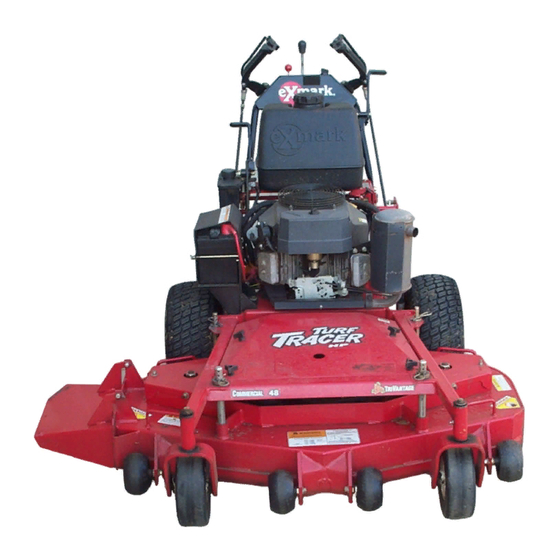
- Page 1 TURF TRACER ® For Serial Nos. 790,000 & Higher Part No. 4500-358 Rev. A...
- Page 2 Replacements may be ordered through the engine manufacturer. Exmark reserves the right to make changes or add improvements to its products at any time without incurring any obligation to make such changes to products manufactured previously.
-
Page 3: Introduction
All Exmark parts are thoroughly tested and inspected before leaving the factory, however, attention is required on your part if you are to obtain the fullest measure of satisfaction and performance. -
Page 4: Table Of Contents
Contents Introduction ... 3 Safety ... 5 Safety Alert Symbol ... 5 Safe Operating Practices ... 5 Safety and Instructional Decals ... 10 Specifications ... 14 Model Numbers ... 14 Systems ... 14 Dimensions... 15 Torque Requirements ... 16 Product Overview ... 16 Operation ... -
Page 5: Safety
• Evaluate the terrain to determine what accessories and attachments are needed to properly and safely perform the job. Only use accessories and attachments approved by Exmark. • Wear appropriate clothing including safety glasses, substantial footwear, long trousers, and hearing protection. - Page 6 Safety DANGER In certain conditions gasoline is extremely flammable and vapors are explosive. A fire or explosion from gasoline can burn you, others, and cause property damage. • Fill the fuel tank outdoors in an open area, when the engine is cold. Wipe up any gasoline that spills.
-
Page 7: Slope Operation
Operation WARNING Operating engine parts, especially the muffler, become extremely hot. Severe burns can occur on contact and debris, such as leaves, grass, brush, etc. can catch fire. • Allow engine parts, especially the muffler, to cool before touching. • Remove accumulated debris from muffler and engine area. -
Page 8: Maintenance And Storage
Safety DANGER Operating on wet grass or steep slopes can cause sliding and loss of control. Loss of control and/or loss of operator’s footing could result in a fall with an arm or leg getting under the mower or engine deck which may result in serious injury, death or drowning. - Page 9 WARNING Hydraulic fluid escaping under pressure can penetrate skin and cause injury. Fluid accidentally injected into the skin must be surgically removed within a few hours by a doctor familiar with this form of injury or gangrene may result. • Make sure all hydraulic fluid hoses and lines are in good condition and all hydraulic connections and fittings are tight before applying pressure to...
-
Page 10: Safety And Instructional Decals
1-403005 • New safety signs may be obtained from your authorized Exmark equipment dealer or distributor or from Exmark Mfg. Co. Inc. • Safety signs may be affixed by peeling off the backing to expose the adhesive surface. Apply only to a clean, dry surface. Smooth to remove any air bubbles. - Page 11 1-413327 48 inch and 52 inch Decks Only 1-413421 1-513747 19 HP Kawasaki Electric Start Only 1-553049 98-5954 103-1798 103-1976 19 HP Kawasaki Electric Start Safety...
- Page 12 Safety 103-1977 15 HP and 17 HP Kawasaki Manual Start 103-2076 103-2103 103-2242 103-2243 103-4935...
- Page 13 Safety 109-3148 116-0404...
-
Page 14: Specifications
• Two Hydro Gear variable displacement high efficiency pumps independently coupled to two high efficiency Parker/Ross wheel drive motors. • Hydraulic Oil: Use Exmark Premium Hydro Oil. • Hydraulic Oil Capacity: 2.4 qt. (2.2 L) • Hydraulic Filter is replaceable cartridge type. -
Page 15: Dimensions
Tires & Wheels Drive Pneumatic Pneumatic (Air-Filled) (Air-Filled) 48 & 52 Quantity Tread Turf Master Turf Master Smooth Size 16 x 6.50–8 16 x 7.50–8 Ply Rating Pressure 14 psi 14 psi (97 kPa) (97 kPa) Cutting Deck • Cutting Width: –... -
Page 16: Torque Requirements
Product Overview Torque Requirements Bolt Location Torque Cutter Housing Spindle 140-145 ft-lb (190-197 N-m) Blade Mounting Bolt 55-60 ft-lb (75-81 N-m) (lubricate with anti-seize) 30-35 ft-lb (41-47 N-m) Engine Deck/Mower Deck Support Mount Bolts Anti-Scalp Roller Nyloc 30-35 ft-lb (41-47 N-m) Nut See Figure 9 Anti-Scalp Roller Whizlock 30-35 ft-lb (41-47 N-m) -
Page 17: Operation
Operation Note: Determine the left and right sides of the machine from the normal operating position. Controls Operator Presence Control (OPC) Levers Located on the upper handle assembly directly above the handle grips. When these levers are depressed, the OPC system senses that the operator is in the normal operator’s position. -
Page 18: Park Brake Lever
Operation Park Brake Lever Located on the left side of the unit above the hydraulic tank. The brake lever engages the park brake on the drive wheels. Pull the lever up and rearward to engage the brake. Push the lever forward and down to disengage the brake. -
Page 19: Pre-Start
Pre-Start Fill fuel tanks. For best results use only clean, fresh regular grade unleaded gasoline with an octane rating of 87 or higher. Regular grade leaded gasoline may also be used; however, combustion chamber and cylinder head will require more frequent service. See Engine Owner’s Manual. -
Page 20: Driving The Machine
Operation PTO Engagement DANGER The rotating blades under the mower deck are dangerous. Blade contact can cause serious injury or kill you. Do Not put hands or feet under the mower or mower deck when the blades are engaged. DANGER An uncovered discharge opening will allow objects to be thrown in an operator’s or bystander’s direction. -
Page 21: Adjusting The Cutting Height
Figure 5 1. Drive Lever in neutral 3. Drive Lever in forward position position 2. Drive Lever locked in 4. Drive Lever in reverse neutral position position Driving Forward 1. Release the parking brake. 2. With drive levers locked in “neutral”, shift speed control lever to desired forward speed. -
Page 22: Adjusting The Anti-Scalp Rollers
Operation Figure 6 1. Deck support pin 2. Cutting Height B. The tire pressures are set as directed in Check Tire Pressures in the Maintenance section. C. The length of the rear deck support link assemblies average 6.89 inches (approximately 6 7/8 inches) (175.01 mm) from the center of the balljoint to the center of the farthest hole. -
Page 23: Transporting
Figure 8 For cutting heights above 3.5 inches (38 mm) use the bottom hole. The rollers will still be effective against scalping. 1. Anti-scalp roller 2. Cutting height mounting bracket 7. Torque the 3/8–16 whizlock nut to 30-35 ft-lb (41-47 N-m) (Figure 9). 8. -
Page 24: Maintenance
Maintenance Maintenance Note: Determine the left and right sides of the machine from the normal operating position. WARNING While maintenance or adjustments are being made, someone could start the engine. Accidental starting of the engine could seriously injure you or other bystanders. Remove the key from the ignition switch, engage parking brake, and pull the wire(s) off the spark plug(s) before you do any... -
Page 25: Periodic Maintenance
Maintenance Service Maintenance Procedure Interval • Change the hydraulic filter (Every 250 hours/yearly if using Mobil 1 15W50) Every 500 hours • Check wheel hub-slotted torque specification. • Check the battery charge. Monthly • Grease the PTO engagement bellcrank. Periodic Maintenance Check Engine Oil Level Service Interval: Before each use or daily 1. -
Page 26: Replacing The Discharge Deflector
Always install the original Exmark blades, blade bushings, and blade bolts as shown. Replacing the Discharge Deflector... -
Page 27: Check Safety Interlock System
PTO is engaged or the engine will kill. Note: If machine does not pass any of these tests, do not operate. Contact your authorized EXMARK SERVICE DEALER. Important: It is essential that operator safety mechanisms be connected and in proper operating condition prior to use for mowing. -
Page 28: Change Engine Oil
2. Clean area around hydraulic reservoir cap and remove cap. Oil level should be to the top of the baffle inside the tank. If not, add oil. Use Exmark Premium Hydro oil. Replace hydraulic reservoir cap and tighten until snug. Do Not overtighten. -
Page 29: Check Spark Plugs
Service Interval: After the first 250 hours 40 hours 40 hours Yearly Note: Use only Exmark Part No. 109–4180 for Summer use above 32°F (0°C) or P/N 1-523541 for Winter use below 32°F (0°C) (Refer to Transmission section in Specifications for filter specifications). -
Page 30: Hydraulic System Air Purge
Maintenance 5. Loosen filter 1/2 turn and allow a small amount of oil to leak from the oil filter (this allows air to be purged from the oil filter and supply hose from the hydraulic reservoir). Turn filter clockwise until rubber seal contacts the filter adapter. Then tighten the filter an additional 2/3 to 3/4 turn. -
Page 31: Wheel Hub-Slotted Nut Torque Specification
a steady flow of oil to flow out from under the housing. Retighten the capscrews. Do this for both pumps. Note: Hydraulic reservoir can be pressurized up to 5 psi to speed this process. 6. If either drive wheel still does not rotate, stop and repeat steps 4 and 5 above for the respective pump. -
Page 32: Mobil Hts Grease (Or Food-Grade Anti-Seize)
Maintenance Mobil HTS Grease (Or Food-Grade Anti-seize) Mobil HTS grease (or food-grade anti-seize) is used in the following locations: • Between the cutter housing spindle and bearings. • Between the cutter housing spindle and sheave. • Under top cutter housing bearing guard. Copper-Based Anti-seize Copper-based anti-seize is used in the following locations:... - Page 33 Adjust the threaded yoke at the bottom of the speed control linkage (see Figure 15) until the tabs are positioned correctly. Figure 15 Viewed from Left Side of Unit 1. Neutral Safety Switch 3. 5/16 inch (.76 cm) 2. Actuating Tab in neutral position 3.
- Page 34 Maintenance disengaged whenever speed control levers are moved out of the neutral position. Note: The neutral lock latches should be “unlocked” and in the forward position. 2. Loosen the front nut on left hydro control linkage as shown in Figure 16. Turn the rear control linkage adjusting nut counterclockwise until wheel rotates forward.
-
Page 35: Hydro Pump Spring Tension Setting
the machine, remove jack stands and carefully lower the machine to the ground. (Check the drive tire pressure and tire circumference see Check the Tire Pressures section.) 2. Run the unit and observe the tracking on a level, smooth, hard surface such as concrete or asphalt. -
Page 36: Cleaning
Maintenance Cleaning Clean Engine and Exhaust System Area Service Interval: Before each use or daily (May be required more often in dry or dirty conditions.) CAUTION Excessive debris around engine cooling air intake and exhaust system area can cause engine, exhaust area, and hydraulic system to overheat which can create a fire hazard. -
Page 37: Battery Disposal
Battery Disposal DANGER Battery electrolyte contains sulfuric acid, which is poisonous and can cause severe burns. Swallowing electrolyte can be fatal or if it touches skin can cause severe burns. • Wear safety glasses to shield eyes, and rubber gloves to protect skin and clothing when handling electrolyte. -
Page 38: Troubleshooting
Troubleshooting Troubleshooting Important: It is essential that all operator safety mechanisms be connected and in proper operating condition prior to mower use. When a problem occurs, do not overlook the simple causes. For example: starting problems could be caused by an empty fuel tank. The following table lists some of the common causes of trouble. - Page 39 Problem Mower pulls left or right (with levers fully forward). Machine does not drive. Uneven cutting height. Abnormal vibration. Blades do not rotate. Possible Cause 1. Tracking needs adjustment. 2. Tire pressure in drive tires not correct. 1. Bypass valve is not closed tight. 2.
-
Page 40: Schematics
Schematics Schematics 15 & 17 HP KAWASAKI SAFETY INTERLOCK MODULE YELLOW BLACK BROWN CONNECTORS ARE VIEWED FROM WIRE END N.C. = NORMALLY CLOSED N.O. = NORMALLY OPEN G006978 19 HP KAWASAKI ELECTRIC START PARK BRAKE SWITCH N.C. ENGINE SOLENOID ENGINE GROUND SOLENOID + SOLENOID... - Page 41 Schematics Hydraulic Diagram...
- Page 42 • Attorney's fees. No Claim of breach of warranty shall be cause for cancellation or rescission of the contract of sale of any Exmark mower. All implied warranties of merchantability (that the product is fit for ordinary use) and fitness for use (that the product is fit for a particular purpose) are limited to the duration of the express warranty.
- Page 43 Notes:...
- Page 44 Notes:...
-
Page 45: Service Record
Service Record Date: Description of Work Done: Service Done By:... - Page 48 SEE EXMARK’S COMPLETE LINE OF ACCESSORIES AND OPTIONS MID-MOUNT RIDING ACCESSORIES AND OPTIONS CUSTOM RIDE SEAT SUSPENSION SYSTEM FULL SUSPENSION SEAT DECK LIFT ASSIST KIT HITCH KIT LIGHT KIT V POWER PORT MICRO-MULCH SYSTEM OUT-FRONT RIDING ACCESSORIES AND OPTIONS CUSTOM RIDE SEAT SUSPENSION SYSTEM...
Need help?
Do you have a question about the Turf Tracer HP 4500-358 and is the answer not in the manual?
Questions and answers