Table of Contents
Advertisement
Owner's Manual
POWER
MISERTM
6
GAS WATER
HEATER
FOR POTABLE
WATER HEATING
ONLY.
NOT SUITABLE
FOR SPACE HEATING.
NOT FOR USE IN MOBILE
HOMES.
MODEL NO.
153.336334
30 Gallon Short
153.336372
30 Gallon
153.336382
30 Gallon (L.P.)
153.336434
40 Gallon Short
153.336472
40 Gallon
153.336482
40 Gallon Propane (L.P.)
153.336572
50 Gallon
153.336582
50 Gallon Propane (L.P.)
This water heater
complies
with ANSI Z21.10.1-
current
edition
regarding
the
accidental
or
unintended
ignition
of flammable
vapors,
such
as those emitted
by gasoline.
Read and understand instruction
manual and safety messages
before installing, operating or
servicing this water heater.
Failure to follow instructions and
safety messages could result in
death or serious injury.
Instruction manual must remain
with water heater.
Si no puede
leer o entender
el ingles
y necesita
el manual
de
instrucciones
en espaSol, puede solicitarlo al 1-800-821-2017.
NO
TRATE DE INSTALAR U OPERAR
ESTE CALENTADOR
DE AGUA
SI NO ENTIENDE
LAS INSTRUCCIONES.
No hacer caso de esta
advertencia
podria originar lesiones graves o mortales.
• Safety Instructions
• Installation
• Operation
• Care and Maintenance
• Troubleshooting
• Parts List
For Your Safety
AN ODORANT
ISADDED
TO THE GAS USED BY THIS WATER HEATER.
WARNING:
If the
information
in these
instructions
is not followed
exactly, a fire
or explosion
may result causing
property
damage,
personal
injury or death.
--Do
not store
or use gasoline
or other
flammable
vapors
and
liquids
in the
vicinity of this or any other appliance.
-- WHAT TO DO IF YOU SMELL GAS:
• Do not try to light any appliance.
• Do not touch any electrical
switch;
do
not use any phone in your building.
• Immediately
call
your
gas
supplier
from a neighbor's
phone.
Follow
the
gas supplier's
instructions.
• If you cannot
reach
your gas supplier,
call the fire department.
--Installation
and
service
must
be
performed
by
a
qualified
installer,
service agency or the gas supplier.
Sears,
Roebuck
and Co.,
Hoffman
Estates,
IL 60179
U.S.A
PRINTED
IN THE U.S.A
0410
www.sears.com
PART NO. 186496-004
Advertisement
Table of Contents
Troubleshooting

Related Manuals for Kenmore POWER MISER 153.336334


Summary of Contents for Kenmore POWER MISER 153.336334
- Page 1 Owner's Manual POWER MISERTM GAS WATER HEATER FOR POTABLE WATER HEATING ONLY. NOT SUITABLE FOR SPACE HEATING. NOT FOR USE IN MOBILE HOMES. • Safety Instructions • Installation MODEL NO. • Operation 153.336334 30 Gallon Short • Care and Maintenance 153.336372 30 Gallon •...
-
Page 2: Safe Installation, Use And Service
Your safety and the safety of others is extremely important in the installation, use and servicing of this water heater. Many safety-related messages and instructions have been provided in this manual and on your own water heater to warn you and others of a potential injury hazard. - Page 3 Fire Hazard Read and understand instruction manual and safety messages For continued protection against before installing, operating or risker fire: servicing this water heater. • Do not install water heater on Failure to follow instructions and carpeted floor. safety messages could result in death or serious injury.
-
Page 4: Table Of Contents
SAFE INSTALLATION, USE AND SERVICE ....................SAFETY PRECAUTIONS ........................... PRODUCT WARRANTY ..........................CUSTOMER RESPONSIBILITIES ......................... PRODUCT SPECIFICATIONS ........................MATERIALS AND BASIC TOOLS NEEDED ....................TYPICAL INSTALLATION ..........................IMPORTANT INFORMATION ABOUT THIS WATER HEATER ..............Installation Checklist ..............................INSTALLATION INSTRUCTIONS ......................12-15 Removing the Old Water Heater .......................... - Page 5 OPERATING YOURWATERHEATER ....................23-25 Lighting Instructions ............................Checking t he Draft ............................BurnerFlames .............................. Emergency S hutDown ........................... Water T emperature Regulation ......................... 24-25 SERVICE ANDADJUSTMENT ....................... 26-28 VentSystem Inspection ..........................BurnerInspection ............................Burner C leaning ............................Housekeeping ...............................
-
Page 6: Product Warranty
Agreements Congratulations making smart purchase. Your • $250 Food Loss Protection annually for any food spoilage Kenmore ® product designed manufactured years that is the result of mechanical failure of any covered of dependable operation. But like all products, it may... -
Page 7: Customer Responsibilities
Thank You forpurchasing aKenmore water heater. Properly installed Massachusetts Code requires this water heater to be installed in and maintained, itshould g ive youyears o ftrouble f ree service. If accordance with Massachusetts 248-CMR 2.00: State Plumbing you should decide that y ou want the new water heater professionally Code and 248-CMR 5.00. -
Page 8: Product Specifications
MODEL TANK CAPACITY TYPE INPUT RECOVERY MINIMUM DIAMETER DIMENSIONS NUMBER IN GALS (LTRS) RATE RATE GALS. VENT PIPE INCHES INCHES (mm) (Btu/hr) PER HOUR DIA. INCHES (mm) HEIGHT @ 90°F RISE (mm) JACKET 153.336334 30 (114) Natural 35,500 36.34 3 (76)or4(102) 18 (457) 46.38 (1178) 153.336372... -
Page 9: Materials And Basic Tools Needed
MATERIALS NEEDED To simplify the installation Sears has available the installation parts shown below. You may or may not need all of these materials, depending on your type of installation. METAL DRAIN PANS EXPANSION TANKS FOR AVAILABLE IN 20" (508 THERMAL EXPANSION mm) DIAMETER... -
Page 10: Typical Installation
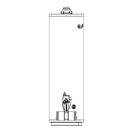
GET TO KNOW YOUR WATER HEATER - GAS MODELS Inner Door Gas Control Valve/Thermostat Vent Pipe Draft Hood Outer Door Drain Valve Union Pilot and Main Burner Anode (Not Shown) Hot Water Outlet Inlet Water Shut-off Valve Flue Insulation Cold Water Inlet Metal Drain Pan Gas Supply Piping Inlet Dip Tube... -
Page 11: Important Information About This Water Heater
This gas water heater was manufactured to voluntary safety standards to reduce the likelihood of a flammable vapor ignition incident. The new technology used in meeting these standards makes this product more sensitive to installation errors. Please review the following checklist and make any required installation upgrades or changes. Questions? Contact Sears at 1-800-4-MY-HOME (1-800-469-4663). -
Page 12: Removing The Old Water Heater
Attach a hose to the water heater Removing the Old Water Heater drain valve and put the other end in a floor drain or outdoors. (See Figures 2 and 5.) Open the water heater drain valve. The water passing out of the drain valve may be extremely hot. -
Page 13: Location Requirements
area of the water heater, leave the area immediately and call Location Requirements the fire department from a neighbor's home. Do not attempt to clean the spill until all ignition sources have been extinguished. Carbon Monoxide Poisoning Hazard Fire or Explosion Hazard Do not install in a mobile home. -
Page 14: Insulation Blankets
Kenmore products. The purpose of an insulation blanket is to reduce the standby heat toss encountered with storage tank heaters. Your Kenmore water heater meets or exceeds the National Appliance Energy Conservation Act standards with respect to insulation Property... -
Page 15: Filling The Water Heater
Open the cold water supply valve to the water heater. II _,_VEHT NOTE: The cold water supply valve must be left open when the water heater is in use. T r- BACK SIDES To ensure complete filling of the tank, allow air to exit by opening the nearest hot water faucet. -
Page 16: Gas Pressure
Gas Pressure the fuel is not spilled in the area of the water heater installation, or any source of ignition. If the fuel is spilled while purging the piping system of air follow the "WHAT TO DO IF YOU SMELL GAS"... -
Page 17: Combustion Air Supply & Ventilation
TABLE 3 120,000 25 x 30 Carbon Monoxide Warning 135,000 28 x 30 Follow all the local and state codes or, in the absence of IMPORTANT: local and state codes, the "National Fuel Gas Code", The area must be open and be able to provide the proper ANSI Z223.1 (NFPA 54)- current edition to properly air requirements to the water heater. -
Page 18: All Air From Outdoors
gas utilization equipment in the area. If you are unsure that the TABLE 4 structure meets this requirement, contact your local gas utility Minimum Free Area of Permanent Openings for Ventilation company or other qualified agency for a safety inspection. and Combustion Air Supply - All Air from Outdoors Only. -
Page 19: Vent Pipe System
using the manufacturer's instructions and local codes, rules, or regulations. 2000 BTUH IMPORTANT: If you tack the necessary skills required properly install this venting system, you should not proceed, but get help from a qualified technician. CONFINED Draft Hood Installation SPACE L SCREWS (FOUR PROVIDED) -
Page 20: Vent Connectors
• The vent connector must be accessible for cleaning, separation, and maintain clearances to combustible materials inspection, and replacement. (Figures 20 and 21). • Vent connectors cannot pass through any ceiling, floor, IMPORTANT: This gas vent must be terminated in a vertical firewall, or fire partition. -
Page 21: Water System Piping
Piping Installation IN A CLOSED SYSTEM USE A _THERMAL EXPANSION TANK Piping, fittings, and valves should be installed according to the COLD pW_;_: uSRIJ EPPELYDTO IF_XTUARtv S installation drawing (Figure 22). If the indoor installation area is subject to freezing temperatures, the water piping must be WATER COLD... -
Page 22: Closed System/Thermal Expansion
For protection against excessive pressures and temperatures, Closed System/Thermal Expansion a temperature and pressure relief valve must be installed in the opening marked "T & P RELIEF VALVE." (See Figure 24). This valve must be design certified by a nationally recognized testing laboratory that maintains periodic inspection of the production of listed equipment or materials as meeting the requirements... -
Page 23: Operating Yourwaterheater
Lighting Instructions Read understand these directions thoroughly before attempting to light or re-light the pilot. Make sure the view port Explosion Hazard is not missing or damaged. (See Figure 32.) Make sure the Replace view port if glass is missing tank is completely filled with water before lighting the pilot. -
Page 24: Checking The Draft
Checking the Draft Water Temperature Regulation IF!I1,7_,I#[,-1=I:I Water temperature over 125°F (52°C) can cause servere burns instantly resulting in severe injury or death. Burn Hazard Children, the elderly, and the physically or mentally disabled are at highest risk for scald injury. Do not touch vent. - Page 25 (normal shower temp.) INDEX BAR (pain threshold) 155°F,_ 35 minutes 45 minutes 1 minute 5 minutes 150OF._ 5 seconds 25 seconds 2 seconds 5 seconds 1 second 2 seconds instantaneous 1 second (U.S. GovernmentMemorandum, C.I_S.C.,Peter L.Armstrong, Sept. 15,1978) 130OF 120°F TEMPERATURE TEMPERATURES SHOWN...
-
Page 26: Service Andadjustment
At least once a year, a visual inspection should be made of the Vent System Inspection main burner and pilot burner. See Figure 29. You should check for sooting. Soot is not normal and will impair proper combustion. Soot build-up indicates a problem that requires correction before Carbon Monoxide and Fire Hazard further use. -
Page 27: Housekeeping
Anode deterioration depends on water conductivity, not necessarily Housekeeping water condition. A corroded or pitted anode rod indicates high water conductivity and should be checked and/or replaced more Vacuum around base of water heater for dust, dirt, and lint on often than an anode rod that appears to be intact. -
Page 28: Service
operation. Thewater h eater s hould bedrained if being shut If thewaterheater i s going tobeshutdown foranextended down during freezing t emperatures. Todrain thetank, p erform period, thedrain valve should b eleftopen. thefollowing steps: IMPORTANT: Condensation may occur w hen refilling t hetank andshould n otbeconfused witha tank leak. -
Page 29: Maintenance Of Yourwaterheater
Replacement Parts CONTROL VALVE/ THERMOSTAT IMPORTANT: The following maintenance procedures are for IGNITER BUTTON the FVIR System components and should be performed by a MANIFOLD TUBE PILOT qualified technician. THERMOCOUPLE TUBE Replacement parts may be ordered from Sears Parts and Service THERMAL VIEW PORT SWITCH... -
Page 30: Replacing T He Pilot/Pilot T Ubeassembly
Position the new thermocouple through the bottom opening Connect the new pilot tube and tighten the nut securing it to of the manifold component block (Figure 34). Be sure the pilot assembly. IMPORTANT: Keep the pilot orifice in igniter wire is positioned through the small opening of the the pilot when making the connection. -
Page 31: Replacing T He Manifold/Burner Assembly
control valve/thermostat. Finally, start the thermocouple Replacing the Manifold/Burner Assembly and turn it all the way in by hand. An additional quarter turn with a 3/8" open-end wrench will then be sufficient to seat the lockwasher. When you are finished, connect the two wire leads that go to the thermal switch. -
Page 32: Testing Theignitersystem
Reconnect the gas piping to the gas control valve/ Testing the Igniter System thermostat. NOTE: Use an approved Teflon tape or pipe Turn off the gas to the water heater at the manual gas shut-off compound on the gas piping connections. valve. -
Page 33: Troubleshooting Guide
Start Up Conditions NOTE: Expansion tanks are pre-charged with a 40 psi air charge. If the inlet water pressure is higher than 40 psi, the expansion tank's air pressure must be adjusted to match Thermal Expansion that pressure, but must not be higher than 80 psi. WATER HEATER INLET FITTING REDUCING... -
Page 34: Operational Conditions
drawn toward the draft hood, shut off water heater and make result of four factors which must all be present for the odor to necessary air supply changes to correct. develop: • a concentration of sulfate in the supply water. Condensation •... - Page 35 if the flame is absent. This unit is also equipped with a thermal switch, designed to shut off the gas supply in the event the water heater has been exposed to flammable vapors (e.g., spilled gasoline), poor combustion caused by a blocked vent or Read and understand instruction insufficient combustion air.
-
Page 36: Troubleshooting Chart
PROBLEM POSSIBLE CAUSE(S) CORRECTIVE ACTION BURNER WILL NOT IGNITE Pilot not tit Light pilot Thermostat set too low Turn temp. dial to desired temperature No gas Check with gas utility company Dirt in the gas lines Notify utility-install trap in gas line Pilot line clogged Clean, locate source and correct Main burner line clogged... - Page 37 PROBLEM POSSIBLE CAUSE(S) CORRECTIVE ACTION THERMOSTAT FAILS TO Thermostat not functioning properly Replace thermostat SHUT-OFF Improper calibration Replace thermostat COMBUSTION ODORS Insufficient secondary air Provide ventilation to water heater. Check flue way, flue baffle, and burner Water heater flue vent system Clean, locate source and correct blocked...
-
Page 38: Pilotlighttroubleshooting Flowchart
Does pilot light go out when i./ ,.in• ICheck Draft. (See "Checking the button s re eased? r NO '_Draft" section of this manual.) ÷ Test the thermocouple using the following procedure: Disconnect the thermocouple from the • ISecure connections Has the thermal switch Are the wires from the gas gas control valve/thermostat. -
Page 40: Partsorderlist
POWER MISER 6 GAS WATER HEATER 153.336334 30 Gallon Short (Natural) (_-_ 153.336372 30 Gallon Tall (Natural) 153.336434 40 Gallon Short (Natural) 153.336472 40 Gallon Tall (Natural) 153.336572 50 Gallon Tall (Natural) Model Numbers Key No. Part Description 153.336334 153.336372 153.336434 153.336472 153.336572... - Page 41 POWER MISER 6 GAS WATER HEATER (Z).. 153.336382 30 Gallon Tall (L.R) 153.336482 40 Gallon Tall (L.R) 153.336582 50 Gallon Tall (L.R) " 11 z:z Model Numbers 153.336382 153.336482 153.336582 Key No. Part Description Anode Rod 9003944 9003944 9003944 9006616 9006616 9006660 Base-Ring...
- Page 44 Your Home iiiiiiiiiiiiiiii:iiiiiiiiiii SearsParts&RepairServiceCenter iiiiiiiiiiiiiiiiiiii ii!!i 1-800-488-1222 (U.S.A.) 1-800-469-4663 iiiiiiiiiiiiiiiiiiii (Canada) i i iiiiiiiiii! www,earscom www,earsca TopurchaseaprotectionagreementonaproductservicedbySears: 1-800-827-6655 (U.S.A.) 1-800-361-6665 (Canada) iiiiii!i!iiiiiiiiiiiiiiiiiiiiiii Para pedirserviciodereparaci6n Au Canada pourserviceenfran_ais: iiiiiiiiiiiiiiiiiiii i!iiiiiiiiiiiiiiiiiiii!ii!!i!i!!i a domicilio, y para ordenarpiezas: 1.800.LE.FOYERMC iiiiiiiiiiiiiiiiiiii iiii_iiiiiiiiiiiiiiii 1-888-SU-HOGAR® 1 800 533 6937 "i"i"i"i"i"i"i"i"i"i"i_!iiii `::_:;:_i:ii_ii_ii_ii_ii_ii_ii_ii_iiii_!!_!_!i_i_i_i_i_ii_ii_ii_i_ii_ ..
Need help?
Do you have a question about the POWER MISER 153.336334 and is the answer not in the manual?
Questions and answers