Table of Contents
Advertisement
Advertisement
Table of Contents

Related Manuals for GENTRON GG3500D


Summary of Contents for GENTRON GG3500D
- Page 1 IDwn_P's ManuaJ www. GentronUSA. corn...
- Page 2 Owner's Manual Carbon onoxi Using a generator indoors WiLL KiLL YOU iN MINUTES. Carbon Monoxide Generator exhaust contains high levels of carbon monoxide (CO), a poisonous gas you cannot see or smell. If you can smell the generator exhaust, you are breathing CO.
- Page 3 Owner's Manual Preface Thankyou for using our generator. This manualincludesthe operationand maintenance of the GG3500D All information in this publication is basedon the latest productinformation available at the time of approvalfor printing.We reservethe right to makechangesat anytime without noticeand without incurringand obligation. Thecopyright of this manual belongsto our company.No parts of this publicationmay bereproducedwithout written permission.
- Page 4 Owner's Manual Safety Instruction /_ WARNING! Thegeneratoris designedto give safeand dependableserviceif operatedaccording to instructions. Readand understandthis manualcarefullybeforeoperatingthe generatoror it may causeserious injury and equipment damage. //_ WARNING! Exhaustcontainspoisonouscarbon monoxide. Do not operategeneratorin confinedenvironmentor with anaerator.Only useoutdoors andfar from openwindows doorsand vents. /_ WARNING! The muffler becomesvery hot during operationand remainshot for a while afterstopping the engine.
- Page 5 Owner's Manual Safety Instruction WARNING! • Gasolineis extremelyflammableand is explosiveunder certainconditions.Refuel in a ventilatedareawith enginestopped. • Keepawayfrom cigarette,smoke and sparkswhen refuelingthe generator.Always refuelin a wellwentilatedlocation. WARNING! • Connection for standbypowerto a building electricalsystem must be madeby a qualifiedelectrician.Theconnection must isolatethe generatorfrom utility power,and must comply with all applicablelawsand electricalcodes.Improperconnections to a buildingelectricalsystem canallow electricalcurrentfrom the generatorto backfeed into the utility lines.
-
Page 6: Table Of Contents
Owner's Manual Content 1. COMPONENT IDENTIFICATION 2.SAFETY INSTRUCTIONS 3.SAFETY LABELLOCATIONS 4.PRE-OPERATION CHECK 4.1 Checkthe engineoil level 4.2 Checkthe fuel level 4.3 Checkthe air cleaner 5. GENERATOR USE 5.1 Startingthe engine 5.2 Highaltitudeoperation 5.3 Generatoruse 5.4 AC applications 5.5 Outputand Overloadindicators 5.6 DOapplications 5.7 Startthe engine 5.8 Oil alarm system... -
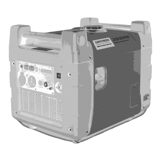
Page 7: Component Identification
Owner's Manual Digital Inverter Generator WARNING! Readthis manual carefullybeforeusing the machine,for your own safety. 1 COMPONENT IDENTIFICATION 1. Fuelcap 9. Overloadindicator light 2. Air vent knob 10. Outputindicatorlight 3. Chokeknob 11. Oilalert indicatorlight 12. Ecothrottle switch 4. Controlpanel 5. Startinggrip 13. -
Page 8: Safetyinstructions
Owner's Manual Control panel DO circuit breaker Eco throttle switch ,:.k, Output indicator light Oil ale_ indicator light Grounding terminal AC socket DC socket Engine switch SMARTTHROTTLE Enginespeedis kept at idleautomaticallywhen the electrical a pplianceis disconnected and it retumsto the proper speedto power of the electricalloadwhen electricalapplianceis connected.This position is recommended to minimizethe fuel consumption while in operation. -
Page 9: Safety Labellocations
Owner's Manual 3. SAFETY LABELLOCATIONS Theselabelswam youfor potentialhazardsthat cancauseseriousinjury. Readthe labelsand safetynotesand precautions describedin the manualcarefully.If a labelcomes off or becomeshardto read,contactyour dealerfor a replacement. _:be! -
Page 10: Pre-Operation Check
Owner's Manual the oil levelis belowthe end of the dipstick, refillthe recommendedoil upto the top of the oilfiler neck. The OilAlert Systemwill automaticallystop the enginebeforethe oil levelfalls belowthe safe limit. However,to avoid the inconvenienceof an unexpectedshutdown, it is still advisableto visuallyinspectthe oil levelregularly. 4.1 Checkengineoil level U__lowed Oil fi[|er hole... -
Page 11: Checkthe Air Cleaner
Owner's Manual Fue! _evel disp|ay Neveruseanoil/gasolinemixture or dirty gasoline. Avoid gettingdirt, dust or water in the fuel tank. After refueling,tightenthe fuelfiller capsecurely. Gasolineis extremelyflammableand is explosiveunder certainconditions. Refuelin awell=ventilated areawith the enginestopped. Do not smoke or allow flames or sparks in the areawherethe engineis refueledor wheregasolineis stored. Do not overfill the fuel tank.After refueling,makesure the tank capis closed properlyand securely. -
Page 12: Generator Use
Owner's Manual 5. GENERATOR USE 5.1 Startingthe engine Beforestarting the engine,disconnectany loadfrom the DCreceptacle. 1) Turn the fuel valveto "ON" position. SL#n _he _Ue_ 1_ _ON _ 2) Putthe electricstart key intothe engineswitch, and turn it to the "ON" position. 3) Tum the electdcstart key to "START"position until the enginehas started. -
Page 13: Highaltitudeoperation
Owner's Manual Thefirst time you startthe engine,or restartthe engineaftera long period of time using the electricstart and if the enginedoes not start.Checkthe battery.Thebatterymight be drained.You canstart the generatorusingthe manualpull start. Usingthe recoil start 1) Turn the fuel valveto the "ON" position. 2) Putthe electricstart key intothe engineswitch, and turn it to the "ON"... -
Page 14: Generatoruse
Owner's Manual Operationof the generatorat lower altitudethan the carburetor isjettedfor may result in reducedperformance, overheating,and seriousenginedamagecausedby an excessively leanair/fuelmixture. 5.3 Generatoruse 5.3.1 W ARNING! • To preventelectrical s hockfrom faulty appliances,the generatorshould begrounded. Connectanelectricconductor (cable)of at least1.5mm to 2mm betweenthe generator'sgroundterminal and an extemalground source. •... -
Page 15: Outputand Overloadindicators
Owner's Manual 5.5 Outputand Overloadindicators. The output indicator light (green)will remain lightedduring normal operatingconditions. If the generatoris overloadedor if there is a short in the connectedappliance,the output indicatorlight (green)will go OFF,the overloadindicator light (red)will go ONand currentto the connectedappliancewill beshut off. Stop the engineif the overloadindicatorlight (red)switchesON and investigatethe overloadsource. -
Page 16: Doapplications
Owner's Manual _When the output indicator light (green)does not light and the overloadindicator light (red) lights instead,set the engine switch to STOP,stop the engineat onceand then start the engineagain. 3. Confirmthat the equipmentto beused is switched off, and insertthe plug of the equipmentto beused into the AC receptacle unitA. - Page 17 Owner's Manual Loadingvoltage(V) Loadingvoltage(V) Loadingcurrent (A) Openingthe smart throttle Closingthe smart throttle DOMax. Outputpower 13.5 Thegeneratorcannotsensea sensibilityloadwith the same powerwhich the manualindicates°£It only cansense40%-70% powerwhich the manualindicates. Example: Model GG3500D 3.0 KVA Generatorratedoutput Frequency Powerfactor 3500 W 0.4-0.75 0-1400W~-2625W 100W(12V/8.3A) •...
-
Page 18: Startthe Engine
Owner's Manual 5.7 Startthe engine • The DCreceptaclemay be usedwhile the AC power is in use. • An overloadedDCcircuit will trip the DCcircuit protector.If this happens,disconnectthe DCload beforeresetingcircuit protectorto resumeoperation. OC circuit breaker 5.8 Oil alertsystem • Theoil alertsystem is designedto preventenginedamagecausedby insufficientamountof oil in alertsystem will automaticallyshut down the engine(theengineswitch will remainin the ON position). - Page 19 Owner's Manual 2. Tum the engineswitch to the OFFposition Eie_r;ic stad key 3. Turn the fuel valveto "OFF" p osition. T_rt_ the {_ va|ve kl_Ob the OFF posiUOn. Besure to tightenthe fuel capand the engineswitch is in the "OFF"position when stopping, transporting and/or storingthe generator.
-
Page 20: Maintenance
Owner's Manual 6 MAINTENANCE • The purpose of the maintenanceandadjustmentscheduleis to keepthe generatorin the bestoperatingcondition. • Inspector serviceas scheduledin the tablebelow. Shut offthe enginebeforeperforming any maintenance, I f the enginemust berunning, makesurethe areais well ventilated.Theexhaustcontainspoisonouscarbon monoxide gas. Useauthorizedpartsor their equivalent.Theuseof replacementpartswhich are not of equivalentquality may damage the generator. -
Page 21: Changingoil
Owner's Manual (2) Servicemore frequentlywhen used in dusty areas. (3) Theseitems should be servicedby an authorizeddealer,unlessthe owner hasthe propertools and is mechanicallyproficient. Seathe Shop Manual. Temperature(o) TimeBrchangingoil(houO Recommendedpower_or Normal 100% WARNING!: I f the temperatureof externalenvironmentreachesor higherthan 45° , the generatorsetsshould bestopped working, otherwise,the generatorsetswill be damaged. - Page 22 Owner's Manual RefillOil i., Remove the screws and _en panel 2. Revolve o_t the dJps_i_. _3. Revol_ the oil fil_ingpi_ Jmo _e oil _er ho_eo 4. Use the oH _H_ng bo_e _t the o_ into the erankca_ and ¢_'_ oi_ _e_eL Oil tilting pipe Oil f:illing bottle Pleasedisposeof used motor oil in a manner that is compatiblewith the environment.We suggestyou take it in a...
-
Page 23: Air Cleanerservice
Owner's Manual 6.2 Air cleanerservice A dirty air cleanerwill restrictairflow to carburetor.To preventcarburetor malfunction, Servicethe air cleanerregularly.Servicemore frequentlywhen operatingthe generatorin extremelydirty areas. not usegasolineor low flash point solventsfor cleaning.They areflammable and explosiveunder certainconditions. Loosenthe cover screwand removethe accesspanel. Removethe screwunder the air filter case. Pullthe air filter cartridge down 1.181inches and removethe air filter cartridge. - Page 24 Owner's Manual 2. Takeout the ignition coil rubber boot. ignition coi| rubber boot Removethe spark plug with spark plug wrench. w_ch Spark pl_ugW'_n¢_ inse_t the sc_wdrfver _.|o the holeof the s_ ptu9wrench_ _mover _ spa_ p_ug, ign_ion coil ;tuber _t Visuallyinspect t he sparkplug.
-
Page 25: Sparkarresterservice
Owner's Manual 5. Installthe sparkplug carefullyby hand,to avoid cross threading. 6. Aftera newspark plug hasbeenseatedby hand,it should betightened1/2 tum with a wrench to compressits washer.If a used plug is beingreinstalled,it should only require1/8 to 1/4tums afterbeingseated. 7. Reinstall t he ignitioncoil rubber boot on the sparkplug securely. 8. -
Page 26: Transportation Andstorage
Owner's Manual 7 TRANSPORTING ANDSTORAGE To preventfuel spillagewhen transportingor during temporary storage,the generatorshould besecuredupright in its normal operatingposition,with the engineswitch OFF. Thefuel capvent leveris tumed counter clockwiseto the OFFposition. Allow the engineto cool well beforetuming the fuel capvent leverto the OFFposition, 7.1 Whentransporting generator: •... -
Page 27: Troubleshooting
Owner's Manual 8 TROUBLESHOOTING Enginewill not start: • Checkfuel level • Is the engineswitch andfuel valve"on"? Tum them to the "on" position • Enoughlubricatingoil? Add recommendedoil if neccessary. • Is there fuel in the carburetor?. • Sparkplug works or not? Replacesparkplug Sendthe generatorto an authorizedservicedealerif the generatorstill does not start or call866-896-6881 toll free •... - Page 28 Owner's Manual The equipmentthat connectsto the generatordoes not start: • Is the output indicatoron? • Is the overloadindicatoron? No (Bring the generatorto an authorizeddealer.) • Doesthe electricalequipmentwork when pluggeddirectly? No Restartaftertuming offthe overloadindicater. (Bring the generatorto an authorizeddealer.) Thereis no powerin the DCelectricoutlet. •...
-
Page 29: Technicaldata
Owner's Manual Specification 9.1Size and weight GG35000D Type LxWxH 23.6x 17.7 x 19.68 50/110 Net w eight k g/Ibs 9.2Engine Type 4-stroke O HV 1-Cylinder 269cd357cc Displacement 9.2:1 Compression ratio Engine s peed 2200 ~ 3600rpm Forced Cooling s ystem T.D.I coolingIgnition s ystem Oil c apacity ( L) -
Page 30: Wiring Diagram
_e;nerator se_ ©... -
Page 31: Partsdiagram
Owner's Manual PARTS DIAGRAM... -
Page 32: Partslist
Owner's Manual PARTS LIST PartsDescription PartsDescription EngineAssembly Top cover M8 X 40 Bolt M6 X 12 Bolt Fueltank sleeve IgnitionCoil StatorAssembly Fuelcap M6 X 25 Bolt Fuelleveldisplaycover board M6 X50 Inner6 Comus Bolt Fuelleveldisplaysle,.,e Handle Rotor Assembly FlywheelFan Sheetiron clip StarterCup ConnectionPipe,fuel tank M6 X 20 Bolt... - Page 33 Owner's Manual Clip Handlespongs sleeve Frontcover SparkArrestor Muffler Cover M6 x12 platescrew M6 X 16 PlateScrew Handlestopple M6 X 12 Bolt Inverterassembly Frame inverterbracket Fueltank Inductance M6 X 12 Bolt Rightside board...
Need help?
Do you have a question about the GG3500D and is the answer not in the manual?
Questions and answers