
Related Manuals for Troy-Bilt TB10CS


Summary of Contents for Troy-Bilt TB10CS
- Page 1 Operator’s Manual TM M 2-Cycle Gasoline Trimmer Model TB10CS IMPORTANT: READ SAFETY RULES AND INSTRUCTIONS CAREFULLY P/N 769-01900 (6/05)
-
Page 2: Table Of Contents
INTRODUCTION THANK YOU TABLE OF CONTENTS Thank you for buying this quality product. This modern Service Information ......2 outdoor power tool will provide many hours of useful service. -
Page 3: Rules For Safe Operation
RULES FOR SAFE OPERATION The purpose of safety symbols is to attract your SYMBOL MEANING attention to possible dangers. The safety symbols, and their explanations, deserve your careful attention and understanding. The safety warnings do not by Failure to obey a DANGER: themselves eliminate any danger. - Page 4 RULES FOR SAFE OPERATION • Always stop the engine and allow it to cool before filling • Keep hands, face, and feet at a distance from all the fuel tank. Never remove the cap of the fuel tank, or moving parts. Do not touch or try to stop the cutting add fuel, when the engine is hot.
- Page 5 RULES FOR SAFE OPERATION SAFETY AND INTERNATIONAL SYMBOLS This operator's manual describes safety and international symbols and pictographs that may appear on this product. Read the operator's manual for complete safety, assembly, operating and maintenance and repair information. SYMBOL MEANING SYMBOL MEANING •...
-
Page 6: Know Your Unit
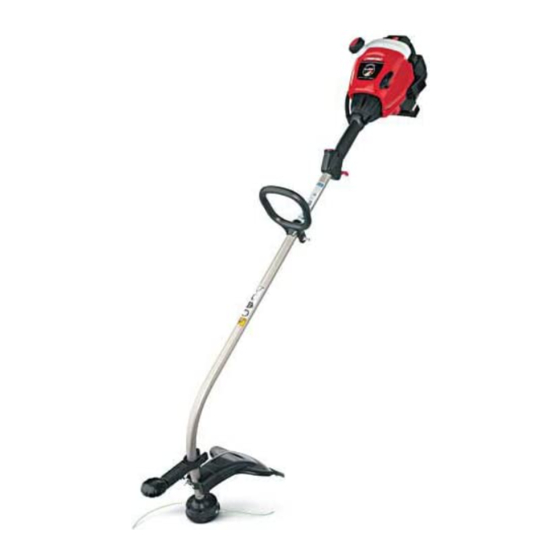
RULES FOR SAFE OPERATION KNOW YOUR UNIT APPLICATIONS Blue EZ-Start™ Lever As a trimmer: Muffler Guard • Cutting grass and light weeds. • Edging Fuel Cap • Decorative trimming around trees, fences, etc. Starter Rope Grip Air Filter/Muffler Muffler Cover Blue EZ-Start Lever Spark Plug... -
Page 7: Assembly Instructions
ASSEMBLY INSTRUCTIONS INSTALL AND ADJUST THE D-HANDLE 2. From inside the cutting attachment shield, push the square bolt through the hole until the threaded end protrudes 1. Push the D-handle down onto the shaft housing so through the guard mounting bracket (Fig. 3). that the handle slants towards the shaft grip (Fig. -
Page 8: Oil And Fuel Information
OIL AND FUEL INFORMATION OIL AND FUEL MIXING INSTRUCTIONS Thoroughly mix the proper ratio of 2-cycle engine oil with unleaded gasoline in a separate fuel can. Use a 40:1 Old and/or improperly mixed fuel are the main reasons fuel/oil ratio. Do not mix them directly in the engine fuel for the unit not running properly. -
Page 9: Starting/Stopping Instructions
STARTING/STOPPING INSTRUCTIONS Stop/Off (O) Operate this unit only in a WARNING: well- ventilated outdoor Start/On ( I ) area. Carbon monoxide exhaust fumes can be lethal in a confined area. WARNING: Avoid accidental starting. Make sure you are in the starting position when pulling the starter rope (Fig. -
Page 10: Operating Instructions
OPERATING INSTRUCTIONS HOLDING THE TRIMMER NOTE: Do not rest the Bump Head™ on the ground while the unit is running. Always wear eye, WARNING: Some line breakage will occur from: hearing, foot and • Entanglement with foreign matter body protection to reduce the risk of injury when operating this unit. - Page 11 OPERATING INSTRUCTIONS USING THE EDGER TO TRIM EDGES 8. When you are done using the edger, move it out of the way. Loosen its wing nut and rotate the edger To properly use the edge guide to trim edges between lawns 180˚...
-
Page 12: Maintenance And Repair Instructions
MAINTENANCE AND REPAIR INSTRUCTIONS MAINTENANCE SCHEDULE NOTE: Maintenance, replacement, or repair of the emission control devices and system may be Perform these required maintenance procedures at the performed by any non-road engine repair frequency stated in the table. These procedures should establishment, individual or authorized service also be a part of any seasonal tune-up. - Page 13 MAINTENANCE AND REPAIR INSTRUCTIONS For Use with Single For Use with SplitLine™ 9. Insert the end of the line into the open hole in the Line ONLY or Single Line inner reel and pull the line tight to make the loop as small as possible (Fig.
-
Page 14: Air Filter Maintenance
MAINTENANCE AND REPAIR INSTRUCTIONS INSTALLING A PREWOUND REEL Cleaning the Air Filter Clean and re-oil the air filter every 10 hours of operation. 1. Hold the outer spool with one hand and unscrew the It is an important item to maintain. Failure to maintain bump knob counterclockwise (Fig. -
Page 15: Carburetor Adjustment
MAINTENANCE AND REPAIR INSTRUCTIONS 8. Replace the two screws you removed in Step 2 and SPARK ARRESTOR MAINTENANCE tighten them securely. NOTE: The exhaust can only flow in one direction: AWAY 9. Reinstall the air filter/muffler cover. from the engine. Pay close attention when disassembling the muffler so you can put it back together correctly. -
Page 16: Cleaning And Storage
MAINTENANCE AND REPAIR INSTRUCTIONS 2. Release the throttle trigger and let the engine idle. If TRANSPORTING the engine stops, insert a small phillips screwdriver • Allow the engine to cool before transporting. into the hole in the air filter/muffler cover (Fig. 31). •... -
Page 17: Troubleshooting Chart
TROUBLESHOOTING ENGINE WILL NOT START C A U S E A C T I O N Empty fuel tank Fill fuel tank with properly mixed fuel Primer bulb wasn't pressed enough Press primer bulb fully and slowly 10 times Engine is flooded Squeeze the trigger and pull the starter rope Old or improperly mixed fuel Drain gas tank and add fresh fuel mixture... -
Page 18: Specifications
SPECIFICATIONS ENGINE* Engine Type............................Air-Cooled, 2-Cycle Stroke ..............................1.25 in. (31.75 mm) Displacement............................. 1.9 cu in. (31 cc) Idle Speed RPM ............................3,200 - 4,400 rpm Operating RPM..............................7,200+ rpm Ignition Type................................Electronic Ignition Switch .............................. Rocker Switch Spark Plug Gap ............................0.020 in. (0.5 mm) Lubrication .............................. - Page 19 • As the small off-road engine owner, you are responsible for the performance of the required maintenance listed in your operator’s manual. Troy-Bilt recommends that you retain all receipts covering maintenance on your small off-road engine, but Troy-Bilt cannot deny warranty solely for the lack of receipts or for your failure to ensure the performance of all scheduled maintenance.
-
Page 20: Warranty Information
(90) days from the date of original retail for related expenses, or for rental expenses to purchase for any Troy-Bilt product that is used for rental or temporarily replace a warranted product. (Some states commercial purposes, or any other income-producing do not allow limitations on how long an implied warranty purpose. - Page 21 Manuel de L'utilisateur TM M Désherbeuse à gaz à 2-temps Modèle TB10CS IMPORTANT: LISEZ LES RÈGLES ET CONSIGNES DE SÉCURITÉ SOIGNEUSEMENT P/N 769-01900 (6/05)
- Page 22 INTRODUCTION TOUS NOS REMERCIEMENTS TABLE DES MATIÈRES Nous vous remercions d'avoir acheté ce produit de Service technique ......F2 qualité.
- Page 23 CONSIGNES DE SÉCURITÉ Les symboles de sécurité attirent votre attention sur SYMBOLE SIGNIFICATION des dangers potentiels. Ces symboles et leurs détails explicatifs méritent que vous les lisiez et compreniez bien. Les avertissements de sécurité ne peuvent éviter le non-respect d’un DANGER: les dangers de par eux-mêmes.
- Page 24 CONSIGNES DE SÉCURITÉ • Gardez les mains, le visage et les pieds éloignés des • Arrêtez toujours le moteur et laissez-le refroidir avant de pièces mobiles. Ne touchez pas et n'essayez pas remplir le réservoir de carburant. N'enlevez jamais le d'arrêter l'accessoire de coupe en rotation.
- Page 25 CONSIGNES DE SÉCURITÉ SYMBOLES DE SÉCURITÉ ET INTERNATIONAUX Ce manuel de l'utilisateur décrit les symboles et pictogrammes de sécurité et internationaux pouvant apparaître sur ce produit. Consultez le manuel de l'utilisateur pour les informations concernant la sécurité, le montage, le fonctionnement, l'entretien et les réparations.
- Page 26 CONSIGNES DE SÉCURITÉ FAMILIARISEZ-VOUS AVEC VOTRE APPAREIL APPLICATIONS Protection du Levier bleu de EZ-Start Utilisation comme désherbeuse : silencieux • Coupe d'herbe et de mauvaises herbes légères. • Coupe de bordures • Tailler autour des arbres, des clôtures, etc. Bouchon du carburant Poignée de la corde de démarrage...
-
Page 27: Instructions De Montage
INSTRUCTIONS DE MONTAGE INSTALLATION ET RÉGLAGE DE LA 2. De l’intérieur de l’écran de l’accessoire de coupe, poussez le boulon carré dans le trou jusqu’à ce que POIGNÉE EN D l’extrémité filetée dépasse de la patte d’attache de 1. Enfoncez la poignée en D sur le corps de l'arbre afin l’écran (Fig. - Page 28 INFORMATIONS SUR L'HUILE ET LE CARBURANT MÉLANGE D'HUILE ET DE CARBURANT Mélangez soigneusement l'huile moteur 2-temps avec de l'essence sans plomb dans un bidon séparé. Utilisez En général, si l'appareil ne fonctionne pas correctement, un rapport 40:1 d'essence/huile. Ne les mélangez pas c'est que le carburant est vieux ou mal mélangé.
- Page 29 INSTRUCTIONS DE DÉMARRAGE ET ARRÊT AVERTISSEMENT: n’utiliser l’outil Stop/Arrêt (O) qu’à l’extérieur, Démarrage/ dans un endroit bien aéré. Les émanations d’oxyde de Allumage (I) carbone dans un endroit confiné peuvent être mortelles. AVERTISSEMENT: évitez tout démarrage accidentel. Tenez-vous en position de démarrage Manette lorsque vous tirez sur la corde de démarrage des gaz...
- Page 30 MODE D'EMPLOI TENUE DE LA DÉSHERBEUSE REMARQUE : Ne posez pas la tête de butée sur le sol lorsque l’appareil est en marche. portez AVERTISSEMENT: Le fil peut se briser dans les cas suivants : toujours des protections (yeux, oreilles, pieds et corps) •...
- Page 31 MODE D'EMPLOI UTILISATION DU COUPE-BORDURE POUR 8. Lorsque vous avez terminé d'utiliser le coupe- TAILLER LES BORDURES bordure, retirez-le. Desserrez l'écrou à oreilles et tourner le coupe-bordure de 180º de la position Pour utiliser correctement le guide bordure pour tailler montrée en Figure 13.
- Page 32 ENTRETIEN ET RÉPARATIONS REMARQUE : certaines procédures d'entretien REMARQUE: l'entretien, le remplacement ou la nécessitent des compétences ou des outils réparation des dispositifs et systèmes particuliers. Si vous n'êtes pas sûr de pouvoir les antipollution peuvent être effectués par tout entreprendre, emmenez votre appareil dans un atelier, technicien ou concessionnaire agréé...
- Page 33 ENTRETIEN ET RÉPARATIONS Utiliser avec le SplitLine 9. Insérez l’extrémité du fil dans le trou ouvert du Utiliser avec le fil simple ou le fil simple UNIQUEMENT moulinet et tirez sur le fil pour que la boucle soit le Trous plus petit possible (Fig.
- Page 34 ENTRETIEN ET RÉPARATIONS Installation d'un moulinet prérembobiné 1. Retirez le couvercle du filtre à air/silencieux. Voir Retrait du couvercle du filtre à air/silencieux. 1. Tenez la bobine extérieure d'une main et dévissez le bouton de butée vers la gauche (Fig. 16). Inspectez le 2.
- Page 35 ENTRETIEN ET RÉPARATIONS 8. Revissez les deux vis que vous avez retirées à l’étape ENTRETIEN DU PARE-ÉTINCELLES 2 et serrez-les bien. REMARQUE : Les gaz de l’échappement ne peuvent circuler que dans une direction: A L’ÉCART du 9. Replacez le couvercle du filtre à air/silencieux. moteur.
- Page 36 ENTRETIEN ET RÉPARATIONS TRANSPORT 2. Relâchez le levier d'accélérateur et laissez le moteur au ralenti. Si le moteur s'arrête, insérez un petit • Laissez le moteur refroidir avant le transport. tournevis à embout cruciforme dans le trou du • Attachez bien l'appareil lors du transport. couvercle du filtre à...
- Page 37 DÉPANNAGE LE MOTEUR REFUSE DE DÉMARRER C A U S E S O L U T I O N Réservoir de carburant vide Remplissez-le de carburant bien mélangé. La poire d'amorçage n'a pas été pressée assez fort Pressez-la complètement et lentement de 10 fois Moteur noyé...
- Page 38 CARACTÉRISTIQUES MOTEUR* Type de moteur..........................Refroidi par air, 2-temps Course ..............................31,75 mm (1,25 po) Cylindrée ............................... 31 cc (1,9 po3) Régime ralenti ............................3.200 - 4.400 tr/min Régime de fonctionnement (désherbeuse)...................... 7.200+ tr/min Type d'allumage..............................Électronique Contact d'allumage ..........................Interrupteur berceau Écartement de la bougie..........................
- Page 39 • Il vous incombe de présenter votre petit moteur à usage tout-terrain à un centre de service agréé Troy-Bilt dès que le problème fait son apparition. Les réparations sous garantie doivent être achevées dans une durée de temps raisonnable ne dépassant en aucun cas 30 jours.
- Page 40 écrite ci-dessus concernant les pièces qui sont identifiées. Aucune autre garantie ou Troy-Bilt LLC garantit ce produit contre tout vice de caution expresse, écrite ou orale, à l'exception de matière ou de façon pendant une période de deux (2) ans celle mentionnée ci-dessus, accordée par toute...
- Page 41 Manuel del Dueño/Operador TM M Recortador de 2 Ciclos Modelo TB10CS IMPORTANTE: LEA LAS REGLAS DE SEGURIDAD E INSTRUCCIONES DETENIDAMENTE P/N 769-01900 (6/05)
- Page 42 INTRODUCCION MUCHAS GRACIAS INDICE DE CONTENIDOS Gracias por haber adquirido este gran producto. Esta Llamadas a apoyo al cliente ....E2 moderna herramienta motriz de exteriores está diseñada para brindarle muchas horas de servicio útil.
-
Page 43: Normas Para Una Operación Segura
NORMAS PARA UNA OPERACION SEGURA Los símbolos de seguridad se utilizan para llamar su SIMBOLO SIGNIFICADO atención sobre posibles peligros. Los símbolos de seguridad y sus explicaciones merecen toda su atención El no obedecer una y comprensión. Los símbolos de seguridad no eliminan PELIGRO: advertencia de ningún peligro por sí... - Page 44 NORMAS PARA UNA OPERACION SEGURA • Mantenga las manos, la cara y los pies lejos de todas • Mezcle y cargue el combustible en un área exterior bien ventilada donde no haya chispas ni llamas. Quite las partes móviles. No intente tocar ni detener el accesorio de corte mientras gira.
- Page 45 NORMAS PARA UNA OPERACION SEGURA SIMBOLOS DE SEGURIDAD E INTERNACIONALES Este manual del operador describe los símbolos y figuras de seguridad e internacionales que pueden aparecer en este producto. Lea el manual del operador para obtener información completa acerca de la seguridad, ensamble, operación y mantenimiento y reparación. SIMBOLO SIGNIFICADO SIMBOLO...
-
Page 46: Conozca Su Unidad
NORMAS PARA UNA OPERACION SEGURA CONOZCA SU UNIDAD APLICACIONES Protector del Palanca azul de EZ-Start™ Como recortadora; silenciador • Corte de césped y hierbas delgadas • Recorte de bordes Tapa del • Recorte decorativo alrededor de árboles, combustible cercos, etc. Mango de la cuerda de arranque Cubierta del... -
Page 47: Instrucciones De Ensamble
INSTRUCCIONES DE ENSAMBLE INSTALACIÓN Y AJUSTE DE LA MANIJA EN D 2. Desde el interior del protector del accesorio de corte, empuje el perno cuadrado a través del orificio hasta 1. Empuje la manija en D hacia abajo sobre el bastidor que el extremo con roscas sobresalga a través del del eje de modo que la manija se incline hacia soporte de montaje de la guardera (Fig. -
Page 48: Información Del Aceite Y Del Combustible
INFORMACION DEL ACEITE Y DEL COMBUSTIBLE INSTRUCCIONES PARA MEZCLAR EL Mezcle bien la proporción correcta de aceite para motor ACEITE Y EL COMBUSTIBLE de 2 ciclos y gasolina sin plomo en una lata de combustible por separado. Use una proporción de 40:1 El combustible viejo o mal mezclado son los motivos de combustible y aceite. -
Page 49: Instrucciones De Arranque Y Apagado
INSTRUCCIONES DE ARRANQUE Y APAGADO Parado/ Use esta unidad ADVERTENCIA: Apagado (O) sólo en un área Arranque/ exterior bien ventilada. Los gases de escape de Encendido (I) monóxido de carbono pueden ser letales en un área cerrada. Evite los ADVERTENCIA: arranques accidentales. -
Page 50: Instrucciones De Operación
INSTRUCCIONES DE OPERACION COMO SOSTENER EL RECORTADOR NOTA: No apoye la Bump Head™ sobre el suelo mientras la unidad esté en funcionamiento. ADVERTENCIA: La línea puede cortarse por: siempre • Enredarse con un objeto extraño protección para sus ojos, audición, pies y cuerpo para reducir el riesgo de una lesión al •... - Page 51 INSTRUCCIONES DE OPERACION CÓMO USAR EL RECORTADOR DE 8. Cuando haya terminado de usar el recortador de BORDES PARA RECORTAR LOS BORDES bordes, quítelo del camino. Aflójele la tuerca de aletas y rote el recortador de bordes a 180º de la Siga estas instrucciones para usar debidamente la guía posición que aparece en la Figura 13.
-
Page 52: Instrucciones De Mantenimiento Y Reparación
INSTRUCCIONES DE MANTENIMIENTO Y REPARACION NOTA: El mantenimiento, la sustitución o arreglo de NOTA: Algunos procedimientos de mantenimiento pueden requerir el uso de herramientas o dispositivos para el control de emisiones y habilidades especiales. Si no está seguro acerca sistemas pueden ser hechos por cualquier de estos procedimientos, lleve su unidad a un establecimiento de reparación, persona o establecimiento de reparación, persona o... - Page 53 INSTRUCCIONES DE MANTENIMIENTO Y REPARACION Para usar SÓLO con 9. Inserte el extremo de la línea en el orificio abierto del Para usar con SplitLine™ línea individual o línea individual carrete interior y tire de la línea en forma ajustada a fin Orificios de que el lazo sea lo más pequeño posible (Fig.
- Page 54 INSTRUCCIONES DE MANTENIMIENTO Y REPARACION INSTALACIÓN DE UN CARRETE PREBOBINADO Limpieza del Filtro de Aire Limpie y vuelva a aceitar el filtro de aire cada 10 horas 1. Sostenga la bobina exterior con una mano y de operación. Es una de las partes cuyo mantenimiento desenrosque la perilla percusiva en sentido es importante.
- Page 55 INSTRUCCIONES DE MANTENIMIENTO Y REPARACION MANTENIMIENTO DEL PARACHISPAS 8. Vuelva a colocar los dos tornilos que quitó en el Paso 2 y apriételos firmemente. NOTA: El flujo de las emisiones puede ser en una dirección solamente: APARTÁNDOSE del motor. 9. Reinstale la tapa del filtro de aire / silenciador. Preste mucha atención a cómo se ensambla el silenciador, de modo que lo pueda volver a armar exactamente como está.
- Page 56 INSTRUCCIONES DE MANTENIMIENTO Y REPARACION AJUSTE DEL CARBURADOR La velocidad lenta del motor puede ser ajustada por la cubierta del silenciador / filtro de aire (Fig. 31). NOTA: Los ajustes realizados sin cuidado pueden dañar seriamente su unidad. Los ajustes del carburador deben ser realizados por un proveedor de Tornillo de servicio autorizado.
- Page 57 INSTRUCCIONES DE MANTENIMIENTO Y REPARACION CAMBIO DE LA BUJIA DE ENCENDIDO ALMACENAMIENTO Use una bujía de encendido Champion RDJ7Y (o similar). • No guarde nunca la unidad con combustible en el tanque La separación correcta es de 0,5 mm (0,020 pulgadas). donde los vapores puedan llegar a una llama o chispa.
- Page 58 RESOLUCION DE PROBLEMAS EL MOTOR NO ARRANCA C A U S A A C C I Ó N El tanque de combustible está vacío Llene el tanque con combustible bien mezclado La bombilla de cebado no fue oprimida lo suficiente Oprima la bombilla de cebado total de 10 veces El motor está...
-
Page 59: Especificaciones
ESPECIFICACIONES MOTOR* Tipo de motor.......................... Enfriado por aire, de 2 ciclos Carrera ............................... 31,75 mm (1,25 pulg.) Desplazamiento ............................31 cm (1,9 pulg R.P.M. de velocidad mínima ......................... 3.200 - 4.400 r.p.m. R.P.M. de operación (Recortador)........................7.200+ r.p.m. Tipo de encendido .............................. Electrónico Interruptor de encendido ........................Interruptor oscilante Separación de la bujía de encendido.................... - Page 60 NOTAS...
- Page 61 Troy-Bilt recomienda que conserve todos los comprobantes que cubren el mantenimiento de su pequeño motor para uso fuera de la carretera, pero Troy-Bilt no puede negar garantía exclusivamente por la falta de comprobantes o por que usted no haya realizado todos los mantenimientos programados.
-
Page 62: Parts List
PARTS LIST ENGINE PARTS - TB10CS 2-CYCLE GAS TRIMMER - ENGINE 23 24 Item Part No. Description Item Part No. Description 753-04887 Starter Housing Assembly 753-04810 Air Cleaner Cover Assembly (includes 2 & 34) (includes 23-30, 32 & 34) 791-180350B Air Cleaner Filter 791-181862 Housing Screw 791-180351... - Page 63 PARTS LIST BOOM AND TRIMMER PARTS - TB10CS 2 CYCLE TRIMMER Item Part No. Description 753-04234 Throttle Housing Assembly (includes 2-4) 791-182405 Switch 791-182690 Throttle Trigger Spring 753-04119 Throttle Trigger 791-181844 Throttle Housing Screws 753-04466 Anti-Rotation Screw 753-04405 Throttle Cable 753-04830 Flexible Drive Shaft 753-04831...
-
Page 64: Garantía
C. Troy-Bilt no le ofrece ninguna garantía a los productos Relación de las leyes estatales con esta Garantía: Esta que sean vendidos o exportados fuera de los Estados garantía le confiere derechos legales específicos, y puede...
Need help?
Do you have a question about the TB10CS and is the answer not in the manual?
Questions and answers