Advertisement
Focusrite Audio Engineering Ltd
Blue Range Modules
User Guide
Jan 2001
o o
o o
o o o o
o o o o
o o o o
o o o o
o o
o o
o o o
o o o
o o o
o o o
o o o
o o o
o o o
o o o
o o o o o o o o o o o o o o o o o o o
o o o
o o o
o o o
o o o
o o o
o o o
o o o
o o o
o o
o o
o o
o o
o o
o
o o
o
o o o o
o o o o
o o
o o
Contents
Overviews
Installation & Operation
Product Information Sheets
Advertisement

Related Manuals for Focusrite Blue Range Modules


Summary of Contents for Focusrite Blue Range Modules
-
Page 1: Table Of Contents
Focusrite Audio Engineering Ltd Blue Range Modules User Guide Jan 2001 o o o o o o o o o o o o o o o o o o o o o o o o o o o o o o o... - Page 2 Accuracy: Whilst every effort has been made to ensure the accuracy and contents of this manual, Focusrite Audio Engineering Ltd make no representations or warranties regarding the contents. We would be most appreciative of any suggestions for improvements, additions or amendments to this manual: please contact the factory at the address below.
-
Page 3: Introduction
This booklet also describes the other modules in the Focusrite range which may be of interest. If you would like to audition or try any of these other modules please contact your dealer or the factory. -
Page 4: Unpacking
There is an IEC mains lead supplied in the package, which should have the correct moulded plug. If the plug is incorrect for your location or country, we're sorry. Please replace it the correct type. The standard wiring colour code used in all Focusrite products is as follows: Brown - Live Blue - Neutral... - Page 5 Fuse Arrangements In most modules there are two fuses inside each module on the supply side of the transformer. For single modules they are ALWAYS 250 mA Anti-Surge type. The fuse value does NOT change when the mains voltage selector switch is changed. This is because we fuse each winding separately.
-
Page 6: Earths And Screens
Earths and Screens In all Focusrite modules the chassis is connected directly to the mains safety earth. For safety reasons we do not provide an earth lifting switch: such a switch can allow for a dangerous wiring arrangement. It is IMPERATIVE that the chassis / mains earth connection is maintained through the IEC lead to the mains safety earth terminal. - Page 7 Blue 230 Dual Mono / Stereo Compressor & Limiters The controls of both of these Dual / Stereo Compressor and Limiter modules are identical for each of the two channels and are simple to use, and are described from left to right along the front panel: Mains switch - this is an illuminated push switch, the indicator is an LED cluster, lit when On.
- Page 8 / limiters, but we believe it to be superior in performance and the combined action of the Focusrite Compressor / Limiter to be less intrusive on the audio. There are,however, two unusual conditions that can arise from this arrangement: There may be occasions when the Compressor is reducing the signal such that there are no longer any peaks remaining above the Limiter Threshold setting selected;...
- Page 9 Blue 245 Analogue to Digital Converter There are only a few controls on the front panel of the Blue 245 , and unlike the other modules the Power switch is on the rear panel . This module should be powered prior to use to allow the entire analogue and clock generator circuits to become electrically and thermally stable before self- calibration .
- Page 10 Should S/PDIF ( IEC958 ) output be required , the following modifications need to be done :- 1) Make an adaptor cable with a female XLR and 2-core cable 2) Connect pin 1 to pin 3 of the female XLR 3) Connect a 330 Ohm resistor in series between pin 2 of the XLR and one core of the cable .
- Page 11 Blue 260 Digital to Analogue Convertor There are only a few controls on the front panel of the Blue 260 , and unlike the other modules the Power switch is on the rear panel. We strongly recommend leaving this module permanently powered wherever possible in fixed installations.
- Page 12 Blue 315 Isomorphic Mastering Equaliser The extreme left side of the panel houses switches for Eq In/Out and Power, apart from these the two channels, mounted one above the other, are identical as are their controls. Starting from the right hand side of the module: Input Level sensitivity is controlled by three sets of rotary controls, first a rotary switch for the course sensitivity with 5dB steps, secondly another rotary switch for the fine sensitivity in _dB steps and finally a continuously variable control with ±1dB range which is only in circuit when the...
- Page 13 Blue 315 MKII Isomorphic Mastering Equaliser The extreme left side of the panel houses switches for Eq In/Out and Power, apart from these the two channels, mounted one above the other, are identical as are their controls. Starting from the right hand side of the module: Input Level sensitivity is controlled by three sets of rotary controls, first a rotary switch for the course sensitivity with 5dB steps, secondly another rotary switch for the fine sensitivity in _dB...
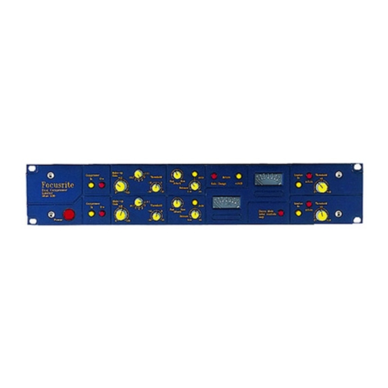
- Page 14 Blue 330 Isomorphic Stereo Mastering Compressor and Limiter The controls are described section by section starting with the two large PPM meters are centrally mounted and controlled by the five meter selection switches in the upper right corner of the module - the signal displayed may be selected from one of four sources, the input, the key input, the total gain change being applied by the compressor section and the output signal.
- Page 15 Blue 330 MKII Isomorphic Stereo Mastering Compressor and Limiter The controls are described section by section starting with the two large PPM meters are centrally mounted and controlled by the five meter selection switches in the upper right corner of the module - the signal displayed may be selected from one of four sources, the input, the key input, the total gain change being applied by the compressor section and the output signal.
-
Page 16: Non-Operation
Miscellaneous Notes Circuit Schematics We do hope that you understand that in an endeavour to protect our designs and intellectual property, Focusrite will only release circuit details (schematics, diagrams) to factory authorised Distributors and Service Centres. Your Comments Despite our being manufacturers we do not have a monopoly on innovation or good ideas and we would appreciate your opinions and comments about our products, and would welcome any suggestions for improvements or additions that you may have thought of. -
Page 17: Warranty
All Focusrite products are covered by a warranty against manufacturing defects in material or craftsmanship for a period of one year from the date of purchase. Focusrite will, at it's own discretion, repair or replace any defective product. This warranty is in addition to your statutory rights.
Need help?
Do you have a question about the Blue Range Modules and is the answer not in the manual?
Questions and answers