Table of Contents
Advertisement
Advertisement
Table of Contents

Related Manuals for Cerwin-Vega CV-5000


Summary of Contents for Cerwin-Vega CV-5000
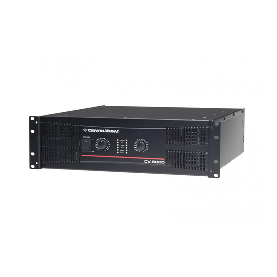
- Page 1 CV-5000 HEAVY DUTY PROFESSIONAL AMPLIFIER USER MANUAL...
- Page 2 IMPORTANT SAFETY INSTRUCTIONS...
-
Page 3: Table Of Contents
TABLE OF CONTENTS Introduction ……………………………………………..4 Features ………………………………………………….. 5 Front Panel Controls …………………………………...…. 6 Rear Panel Controls ………………………………………. 8 Protection ……………………….……………………..10 Setup ………………………………..…………………… 11 Connections …………………………………………..….. 13 Wiring…………………………………………………….. 15 Specifications…………..……………………………. 17... -
Page 4: Introduction
INTRODUCTION Thank you for your decision to purchase Cerwin-Vega’s innovative new CV Series professional power amplifier! Engineered for superior sound reproduction, the CV Series line of professional amplifiers deliver top quality audio at an affordable price. The CV Series offers a standard of reliability and efficiency that makes them the perfect solution for every DJ, musician, and sound engineer. -
Page 5: Features
FEATURES The CV-5000 amplifier delivers the following power ratings. 2 x 1100 Watts at 8 ohm, 2 x 1800 Watts at 4 ohms and 2 x 2500 Watts at 2 ohms 2-channel, parallel or bridged mono operating modes for flexible application - 5000 Watts …and the following features. -
Page 6: Front Panel Controls
FRONT PANEL CONTROLS 1. Rack Mounting Ears Two front panel mounting holes are provided on each mounting ear. 2. Fan Vent CV-5000 amplifier is cooled by two rear-mounted fans. Cool air flows through the front fan filters, reducing the temperature of the inside components while forcing the heat out the rear vents. - Page 7 7. Protect Indicators These red LED indicate that the channel is in Protect mode. When the channel goes into protect mode all output for that channel will turn off by output relay. The protect LED will light when overheating or other severe problems occur. This is to protect any speakers connected to the channel.
-
Page 8: Rear Panel Controls
REAR PANEL CONTROLS 1. Fan This is a variable speed cooling fan. Cool air enters the amplifier through the fan ports located on the front of the amplifier chassis, be sure not to block these ports when installing the amplifier or other associated equipment. 2. - Page 9 5. Limiter switch When the input signal connected to your amplifier is too high, you can end up with a distorted output signal. To prevent this, both channels of your CV-5000 feature a clip limiter that can be engaged or disengaged selectively. 6.
-
Page 10: Protection
PROTECTION The CV-5000 incorporates protection features. The front panel Protection LED indicates the activity of the relay speaker connection circuitry in each channel. When the Protection LED turn on, this circuitry is active and all connected speakers are muted. Initial Power Up - For approximately five seconds after initial power-up, the protection circuitry is activated and the speaker outputs are muted. -
Page 11: Setup
SETUP Clip Limiter Clipping is the result of an amplifier running into a power supply limitation. The maximum output voltage that any amplifier can produce is limited by its power supply. Attempting to output a voltage (or current) level that exceeds the power supply results in a “flattenin” effect on the signal, making it’s waveform look cut off or “clipped”. - Page 12 Mode Select Stereo Mode In stereo mode, both channels operate independently, with their input gain controls. Signal at channel 1’s input produces output at channel 1, while signal at channel 2’s input produces output at channel 2’s output. Recommended minimum nominal load impedance for stereo operation is 2 ohms per channel.
-
Page 13: Connections
CONNECTIONS... -
Page 15: Wiring
WIRING These are several ways to interface the CV-5000 to support a variety of applications. The CV- 5000 features balanced inputs and outputs, so connecting balanced and unbalanced signals is possible. BALANCED TRS 1/4” CONNECTOR UNBALANCED TRS 1/4” CONNECTOR... - Page 16 XLR BALANCED WIRING GUIDE SPEAKON® OUTPUT CONNECTOR...
-
Page 17: Specifications
SPECIFICATIONS 0dB=0.775V 0dBV=1V Rated Output Power Stereo 8 ohms 1100W 4 ohms 1800W 2 ohms 2500W Rated Output Power Bridged Mono 8 ohms 3600W 4 ohms 5000W Signal to Noise Ratio <-100dB (20 Hz ~ 20k Hz) Distortion (SMPTE-IM) < 0.02% Input sensitivity @8 ohms 1.42V (+5.3dB) Voltage Gain... - Page 18 Connectors (each) Input Active balanced combo (XLR and 1/4” TRS common use) XLR male Link Output 5-way Binding post and Speakon Control Front AC power switch, Channel 1 and 2 volume Rear HPF switch, Limiter switch, Mode selector switch Indicators Active(blue), Protection(red), Clip(red), Signal (green &...
- Page 19 Phone: +32 2 645 05 00 • Fax: +32 2 645 05 05 • Email: euroffice@stantoneurope.com Cerwin-Vega! is a division of the Stanton Group Cerwin-Vega! reserves the right to make changes to product specifications and design at any time © Copyright 2010 Cerwin-Vega!
Need help?
Do you have a question about the CV-5000 and is the answer not in the manual?
Questions and answers