Advertisement
Available languages
Available languages
Quick Links
Operator's Manual
®
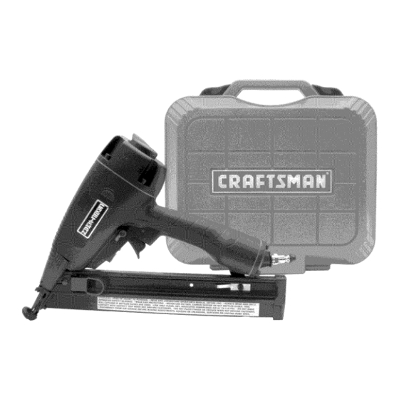
15 Gauge
11/,-21/2 " Length
IN-LINE ANGLE FINISH NAILER
Model No.
351.181770
CAUTION:
Read and follow
all Safety Rules and Operating
Instructions
before First Use
of this Product. Keep this
manual with tool.
Sears, Roebuck and Co., Hoffman Estates, IL 60179 U.S.A.
www.sears.com/craftsman
21202.00 Draft (08/18/03)
• Safety
• Operation
• Maintenance
• Parts List
• EspaSol
Advertisement

Related Manuals for Craftsman 351.181770


Summary of Contents for Craftsman 351.181770
- Page 1 • Safety • Operation all Safety Rules and Operating Instructions before First Use • Maintenance of this Product. Keep this • Parts List manual with tool. • EspaSol Sears, Roebuck and Co., Hoffman Estates, IL 60179 U.S.A. www.sears.com/craftsman 21202.00 Draft (08/18/03)
-
Page 2: Full One Year Warranty
• The tool must have a male, free-flow hose coupling so that all air pressure is removed from the tool when the coupling joint is disconnected. Failure to use proper coupling could Warranty ......... cause accidental discharge, possibly causing injury. Safety Rules ........ -
Page 3: Specifications
15 feet is recommended. Lubricator is not required oilless tools. DESCRIPTION Keep air filter clean. A dirty filter will reduce the air pressure The Craftsman 15 Gauge In-line Angle Finish Nailer drives to the tool causing a reduction in power and efficiency. -
Page 4: Operation
* Insert onenail s trip into the slotlocated ontheend ofthe NAILING OPERATION magazine. Feed strip past n ail s top (see Figure 2). Refer to Figures 5-11 (pages 4, 5 and 6). WARNING: Read and follow all safety rules and operating instructions in this manual and on warning... - Page 5 CONTACT TRIP PAD STORAGE WARNING: All air power fastening tools recoil when operat- ed. This recoil is caused by rapid driving of the fastener. Tool Pad can be removed and stored on the storage sleeve may bounce from recoil causing a second unwanted fastener...
-
Page 6: Exhaust Deflector
• Grasp n ose cover o nbothsides and pull o utward u ntil p in COLD WEATHER OPERATION disengages from latch. Then pull u pward s othat f astener CAUTION: Do not store in cold environment. Frost or ice guide plate swings a way f rom magazine (see Figure 10). could form inside tool affecting operation... - Page 7 CORRECTIVE ACTION CAUSE(S) SYMPTOM POSSIBLE Trigger cap leaks 1. O-ring damaged 1. Check and replace damaged O-ring (Fig. 12, No. 63) 2. Valve stem, seal or O-rings damaged 2. Check and replace damaged stem, seal or O-rings (Fig. 12, Nos. 63, 65, 66 and 69) Cap leaks 1.
- Page 8 Model 351.181770 Figure 12 - Replacement Parts Illustration For Finish Nailer 08.._ o \ 66------_I 64 _ 6 2 -------_...
- Page 9 PART NO. PART NO, DESCRIPTION QTY. DESCRIPTION QTY, 20548.00 Nut Guide 20904.00 Deflector STD870525 5-0.8 x 25mm Socket Head Bolt* 20549.00 Knob 20912.00 STD852005 5mm Lock Washer* Contact Trip Bracket 21329.00 20246.00 3 x 23mm Spring Pin 21335.00 06416.00 Contact Trip 17.8 x 2.4mm O-Ring 06903.00 Seal...
- Page 10 Calibre 15 Mantenga a los nifios, a los visitantes y a toda otra persona una distancia prudente del area de trabajo mientras hace fun- 1¼ - 21/2 , , de Longitud cionar esta herramienta. Los operadores de herramientas neumaticas y todas las CLAVADORA DE ACABADO demas...
- Page 11 O, las valvulas DESCRIPCION los cilindros. La davadora de acabado de angulo en linea 15 Craftsman clava La humedad reducira el rendimiento y la vida Qtil de la herra- clavos de 1V4" a 2/," de Iongitud.
- Page 12 Diferentes materiales de la pieza de trabajo y diferentes largos Deslice la banda de davos hacia la parte frontal del dep6sito de sujetadores requeriran diferentes presiones de operaci6n. hasta que la banda de clavos quede en la oreja (vease la Figura 3).
- Page 13 Realice la"Verificacion del M ecanismo deSeguridad" tal c omo AJUSTE DISPARO POR CONTACTO sedescribe enlasecci6n Mantenimiento (vease lapagina 1 5) El disparo por contacto puede ajustarse hacia arriba o hacia antes d eutilizar laherramienta porprimera y luego d iaria- abajo para variar la profundidad del sujetador en la pieza de tra- mente.
- Page 14 ALMACENAMIENTO DEL SOPORTE DE DISPARO Tapa de la CONTACTO Oreja El soporte puede extraerse y almacenarse en el bolsillo de alma- cenamiento ubicado en el dep6sito. La Ilave hexagonal se alma- cena en el dep6sito (vease la Figura 8). Llave Placa Guia de Sujetadores Figura 10 - Extracci6n de un Sujetador Atascado...
- Page 15 Oprima el gatillo mientras el disparo per contacto esta alejado de la pieza de trabajo y apuntado en direcci6n contraria usted y a otras personas. La herramienta no deber& disparar. Consulte la Figura 12 (pagina Oprima y sostenga el gatillo. Presione el disparo por contacto LUBRICAClON contra la pieza de trabajo donde se debe colocar el sujetador.
- Page 16 SINTOMA MEDIDA CORRECTIVA CAUSAS(S) POSIBLE(S) 1. Anillo O da_ado Se fuga aire por la tapa Revise y cambie el anillo O daSado (Fig. 12, No. 63) del gatillo 2. Wistago de la valvula, sello o anillos O Revise y cambie el vastago, sello o anillos O daSados dar_ados...
- Page 17 NOTAS...
- Page 18 NOTAS...
- Page 19 NOTAS...
- Page 20 iiiiiiiiiiiiiiiiji Your Home iiiiiiiiiiiiiiiii:i For repair-in your home-of all major brand appliances, iiiiiiiiiiiiiiiill lawn and garden equipment, or heating and cooling systems, iiiiiiiiiiiiiiiill no matter who made it, no matter who sold it! iiiiiiiiiiiiiiiiii iiiiiiiiiiiiiiii!} For the replacement parts, accessories iiiiiiiiiiiiiiiii:i owner's manuals that you need to do-it-yourself.
Need help?
Do you have a question about the 351.181770 and is the answer not in the manual?
Questions and answers