Table of Contents
Advertisement
Available languages
Available languages
Advertisement
Chapters
Table of Contents

Related Manuals for Craftsman 196.205680


Summary of Contents for Craftsman 196.205680
- Page 1 Owner's Manual I (RRFTSMRN1 WIRE FEED MIG WELDER Model No. 196.205680 CAUTION: Before using this EspaSol p.27 product, read this manual and follow all its Safety Rules and Operating Instructions. Sears, Roebuck and Co., Hoffman Estates, IL 60179 U.S.A. www.sears.com/craftsman...
-
Page 2: Table Of Contents
Limited Three-Year Warranty on Craftsman Craftsman Limited Warranty .... 2 Table Of Contents ......Welder Safety Summary ........ Important Safety Information ..3 For three years from the date of purchase, Shock Hazards ......any part of this welder, except... -
Page 3: Safety Summary
Note: The following safety alert symbols Every craftsmanrespectsthe tools with identify important safety messages in this manual. which they work. They knowthat the tools When you see one of the symbols represent years of constantly improved shown here, be alert to the possibility designs and developments. - Page 4 SHOCK HAZARDS Do not alter power cord or power cord I.__ ]WARN' O plug in any way. Do not attempt to plug the welder into the power source if the ground prong on power cord plug is bent over, broken off, or missing.
- Page 5 A shieldor helmetwith a number10 instructions as well. REMEMBER! Arc weld- shade filter lens (minimum)mustbe used. ing by nature produces sparks, hot spatter, Do not strike a welding arc untilall molten metal drops, hot slag, and hot metal bystandersand you (the welder) parts that can start fires, burn skin, and haveweldingshieldsand/orhelmets damage...
- Page 6 eliminated from the shirt front. advice and inspection of the ventilation Have fire extinguisher equipment handy the welding area. These metals produce EXTREMELY TOXIC fumes which can for immediate use! A portable chemical cause discomfort, illness, and death. fire extinguisher, type ABC, is recommended.
- Page 7 OSHA Standard 29 CFR, Part 1910, ADDITIONAL SAFETY Subpart Q., WELDING, CUTTING INFORMATION BRAZING - obtainable from your state For additional information concerning OSHA office or U.S. Dept. of Labor welding safety, refer to the following OSHA, Office of Public Affairs, Room standards and comply...
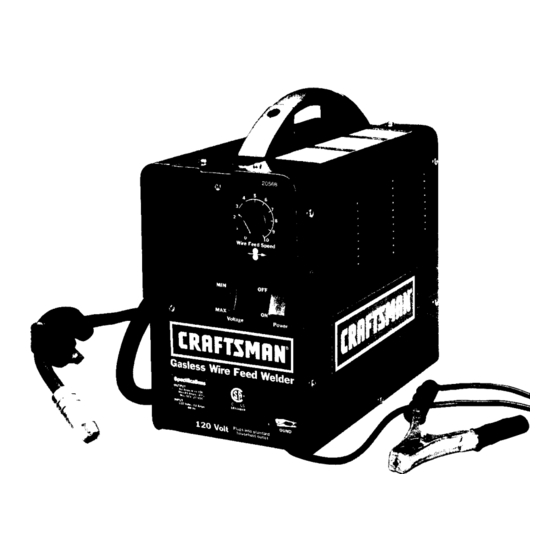
- Page 8 Power Cord - This is a standard, grounded Wire Speed 120 volt power cord. (Make sure you are Handle using a properly grounded 120 Vac, 60Hz, Gun Cable single phase, 20 amp power source.) Ground Clamp - Attaching the ground clamp to your work piece "completes"...
-
Page 9: Unpacking The Welder
ASSEMBLE FACE SHIELD Remove the lens retaining pegs and Thefollowing procedures describe the process shield handle nut from the arm of the requiredto assemble, i nstall,maintain, and pre- shield handle. (DO NOT DISCARD!) pareto weldwithyournewwirefeedac welder. Place the shaded lens into the space provided on the inside of the face shield. -
Page 10: Extension Cords
EXTENSION CORDS through a hole in the outer edge of the For optimum welder performance, an extension spool and is bent over the spool edge to cord should not be used unless absolutely prevent the wire from unspooling) DO NOT UNHOOK IT YET. -
Page 11: Duty Cycle
ground clamp or any grounded piece of metal. IMPORTANT! The welding wire is car- Your new MIG (Metal Inert Gas) Wire Feed rying welding current whenever the welder welder is designed for maintenance turned sheet metal fabrication. The welder consists 11. -
Page 12: Internal Thermal Protection
CAUTION Prepare an organized, well lighted work Do not constantly exceed the duty cycle or area (see Figure 5). damage to this welder can result. Provide protection for the eyes and skin of the operator and bystanders. INTERNAL THERMAL Set up the work piece and make the PROTECTION ground clamp connection. -
Page 13: Preparing The Joint
contact,as in Figure5. The angleof the bevel the regular position. If possible, the work pieces shouldbe approximately 60 degrees. should be clamped into the position they are to INCORRECT occupy when the welding is complete. CORRECT )< ARC RAYS CAN INJURE EYES AND Figure 5. -
Page 14: Learning To Weld
LEARNING TO WELD Angle A (Figure 7) can be varied, but in most cases the optimum angle will be 60 MIG (Metal Inert Gas) welding is the process degrees. The point at which the gun of uniting metallic parts by heating and handle is parallel to the work piece. -
Page 15: Layinga Bead
fromthe restof the gun.This permitsthe operatorto actuallyrestthe nozzleon the work pieceand dragit alongwhilewelding. This can be very helpfulto beginningwelders to steadythe gun,allowingthe welderto con- centrateon weldingtechnique.If the nozzleis PUSH Puddle PULL held off the workpiece,the distancebetween Figure 9. Gun Travel Direction the nozzleand the workpiece shouldbe kept constantandshouldnot exceed1/4 inchor... -
Page 16: Welding Positions
1. The STRINGER BEAD (Figure 10) is 2. The HORIZONTAL POSITION (Figure formed by traveling with the gun in a straight is next in difficulty level. It is performed very line while keeping the wire and nozzle much the same as the flat weld except that centered over the weld joint. -
Page 17: Multiple Pass Welding
MULTIPLE PASS WELDING Butt Weld Joints. When butt welding thicker materials, you will need to prepare the edges Lap Joint Welded of the material to be joined by grinding In Three Passes bevel on the edge of one or both pieces of the metal being joined. -
Page 18: Spot Welding
Do not use 0.030 inch self-shielding flux-core wires when using the burn-through method unless the metal is VERY thin or excessive GENERAL MAINTENANCE filler metal build-up and minimal penetration This welder has been engineered to give is acceptable. many years of trouble-free service providing that a few very simple steps are taken to... -
Page 19: Wire
If the wire burns back into the tip, remove With the welder unplugged from the ac the tip from the gun and clean the hole power source, touch the probes of an ohm- running through it with an oxygen-acety- meter or continuity tester to the end of the lene torch tip cleaner or tip drill. -
Page 20: Maintaining The Welder
The following paragraphs describe Drive Drive procedures required to maintain Tension Tension Assembly troubleshoot your welder. (Tail -nd) Adjustment MAINTAINING THE WELDER Except for internal and external cleaning, cleaning the nozzle, and occasionally retightening screws, there is no periodic maintenance recommended for your welder. - Page 21 TROUBLE POSSIBLE CAUSE POSSIBLE REMEDY Plugged welding nozzle Clean or replace nozzle Dirty, porous, brittle weld Wire feed works but no arc 1. Bad ground or loose 1 Check ground and connection connections. Tighten as necessary. 2. Bad connection to gun or 2.
-
Page 22: Suggested Settings
Code Description Qty. WE20568-21600036 Welder Handle WE20568-05000062 Right Upper Panel WE20568-05000061 FronVLower Panel WE20568-33720108 Dividing Panel WE20568-05000063 Left Side Panel WE20568-05000064 Removable Access Panel WE20568-44120100 Transformer 60Hz 115V 50x70AL WE20568-44135097 Choke _3.9 40x25AL WE20568-04600108 Kit Spool Holder for _16 Spools-Comp. 09a WE20568-21690270 Locking Pin for Spool Holder... - Page 23 GASLESS WIRE FEED WELDER MODEL 196.205680 PARTS DIAGRAM 33 23 9a...
- Page 24 No. Code: Description Qty. WE20568-21690300 Black Gun Handle WE20568-21690301 Red Trigger for Gun WE20568-23005011 Brass Block WE20568-23005145 Gun Neck WE20568-23005091 Thread Guide Wire Liner WE20568-23005090 Conductor Tube Insulation WE20568-23005146 Gas Diffuser WE20568-23005019 0.8mm Contact Tip WE20568-23005147 Nozzle WE20568-33810090 Pin for Gun Trigger WE20568-33800009 No-Gas Gun Contact Spring WE20568-21020012...
- Page 25 GASLESS WIRE FEED WELDER MODEL 196205680 WIRING DIAGRAM ..... MOTOR- MOTOR+ IN -- '+IN...
- Page 26 SUGGESTED SETTINGS FOR WELDER JCRRFTSMAN°I These are recommendations only - variations in input power, welding positions, wire will affect the weld characteristics. Use the voltage setting and wire speed indicated as a starting point - then adjust for variables such as stick out, travel speed, weld angle, cleanliness...
-
Page 27: Sears, Roebuck
Garantia limitada de Craftsman .... 27 Garantia limitada de Tres Aries de la Soldadora indice ............Craftsman Resumen de Seguridad ......28 Informacion Importante Si cualquier parte de esta soldadora, excepto Seguridad ..........per la pistola o los cables, fallase debido a un Riesgos de Choque Electrico .... -
Page 28: Resumen De Seguridad
Nota: Los siguientes sfmbolos de alerta de Todo artesano respeta las herramientas con las seguridad identifican mensajes de seguridad importantes en este manual. que trabaja. Sabe que las herramientas Cuando vea uno de estos simbolos que representan a6os de mejoras y desarrollo se indican a continuaci6n, est6 alerta a la constantes. -
Page 29: Riesgos De Choque Electrico
RIESGOS DE CHEQUE ELECTRICO • No intentar enchufar la soldadora a un tomacorriente si la clavija para conexion a tierra en el enchufe del cordon estuviese doblado, rote o faltante. • No permitir que la soldadora se conecte a un ADVERTENCIA tomacorriente, ni intentar soldar si la... -
Page 30: Riesgos De Incendio
una mancha negra permanente en el campo medidas de seguridad, iRECUERDE! Per su de vision. Debe usarse una careta con un naturaleza, los arcos de soldar producen lente oscuro No. 10 (minimo). chispas, gotean metal derretido y escoria • No encender el arco de soldar hasta que caliente y pedazos de metal caliente que todos los observadores... -
Page 31: Riesgos De Vapores
pantalones o los bolsillos.Lospu6osy los menos que primero se saque el cuellosde las camisasdebenmantenerse recubrimiento. Asegurarse que el area este abotonadas y se debeeliminarlos bolsillos bien ventilada y que el operador y todas las delpechode la camisa. otras personas en el area de la soldadura •... -
Page 32: Informaci6N Adicional De Seguridad
INFORMACION ADICIONAL Norma 29CFR de OSHA, parte 1910, Secci6n Q, Soldadura, Corte y Soldadura DE SEGURIDAD Fuerte: Se puede obtener en la oficina de OSHA en su estado, o en la Secretaria de Para informaci6n adicional referente a la Trabajo de EE.UU. seguridad para soldar, referirse a las siguientes Oficina de Relaciones... -
Page 33: Conozca Su Soldadora
Cordon de Suministro Electrico: Es un cord6n estandar de 120 voltios con Vel de Alim del aqambre conexion a tierra. (Asegurarse de usar un tomacorriente de 120 VCA, 60 Hz, monofasico CabLe de la pistola de 20 amperies). Pinza para Conexion a Tierra: Su conexion a la pieza de trabajo "completa"... -
Page 34: Ensamblaje
ENSAMBLAJE DE LA CARETA PARA SOLDAR 1. Quitar la u_as retenedoras de la lente y El siguiente procedimiento describe el proceso para ensamblar, instalar, mantener y prepararse la tuerca del mango del braze de la para soldar con la nueva soldadora con careta. -
Page 35: Cordenes De Extension
CORDONES DE EXTENSION 2. Quitarle la tapa al eje. 3. Desenrollar el alambre del carrete y encontrar Para el rendimiento 6ptimo de la soldadora, no se deben usar cordones de extensi6n a menos que su extremo (pasa por el orificio en el borde sea absolutamente necesario. -
Page 36: Operacion
conexi6n a tierra, ni otra pieza de metal conectada a tierra, ilMPORTANTE! alambre soldador est& cargado de cordente DESCRIPCION para soldar siempre que la soldadora est_ Su nueva soldadora MIG (Gas Inerte al Metal) con encendida. alimentador de alambre esta diseflada para 12. -
Page 37: Pretecci6N Termica Interna
PRECAUCION • Preparar un area bien organizada No exceder constantemente d elciclonominal iluminada (ver la Figura 5). de trabajoporquese podriada_aresta • Proporcionar proteccion adecuada a los soldadora ojos y la piel del operador y de las personas alrededor. PROTECCION TI_RMICA INTERNA •... -
Page 38: Conexi6N De La Pinza A Tierra
posible, prensarlas en la posici6n que van a muestra en la Figura 5. El angulo del bisel debe ocupar cundo se termine de soldar. set de aproximadamente 60 grados. INCORRECTO CORRECTO >< iLOS RAYOS DEL ARCO PUEDEN LESIONAR LOS OJOS Y QUEMAR LA PIEL! Figure 5. -
Page 39: Aprendiendo A Soldar
APRENDA A SOLDAR Angulo A (Figura 7) puede variarse, pero en la mayoria de los casos el angulo La soldadura MIG (Gas Inerte al Metal) es un optimo es 60 grados; o sea cuando el proceso para unir piezas metalicas mediante mango de la pistola este paralela a la calor generado... -
Page 40: Come Formar El Cord6N De Soldadura
_lectricamente delrestode la pistola. Estopermitequeel operador a poyela boquilla _nla piezadetrabajoy la arrastre al soldar. A si _epuedeaprender a moverestablemente l a _istola, c oncentrandose en la tecaica de soldar. Sise mantiene separada la boquilla de la pieza Jetrabajo,la distancia debeserconstante a EMPUJANDO CIi.rr_ dl ",n_d_ldura... -
Page 41: Posiciones Para Soldar
Cord6n de refuerzo (Figura 10) se hace POSICION HORIZONTAL (Figura 13) es I desplazando la pistola en linea recta a siguiente en grado de dificultad. Se hace con el alambre y la boquilla centrados igual que la soldadura ?lana excepto que el angulo B (ver POSIClON DE LA PISTOLA sobre la junta que se suelda. -
Page 42: Soldadura De Pasadas Multiples
SOLDADURA DE PASADAS MULTIPLES Junta de soldadura a tope. Cuando se suelden a tope materiales gruesos se debe preparar el borde de los materiales biselando Junta traslapada con tres pases el borde de una o ambas piezas de metal que se van a soldar con una esmeriladora. -
Page 43: Instrucciones Para La Soldadura De Puntes
No se debe usar alambre de 0,80mm (0.030") de n0cleo fundente autoprotegido en el metodo de perforacion termica, a menos que el metal MANTENIMIENTO GENERAL sea MUY delgado o acepte una acumulacion Esta soldadora esta disefiada para ofrecer excesiva de material de soldadura muchos afios de servicio sin problemas siempre y penetracion minima. -
Page 44: Prueba De Cortocircuito En La Boquilla
1. Si el alambre se quema dentro de la punta, TIENE CORTOCIRCUITO. Limpiar o reemplazar sacarla de la pistola y limpiar el orificio que la boquilla. la recorre con un limpiador para punta de REEMPLAZO DEL FORRO Antorcha de oxiacetileno o broca para punta. -
Page 45: Mantenimiento De La Soldadura
Los siguientes parrafos detallan los Regulador de Brazo Casco de la procedimientos de mantenimiento y diagn6stico Tension del Tensor de Pistola (Extremo de problemas de la soldadora. Avance Avance de Cola) MANTENIMIENTO DE LA SOLDADORA Aparte de limpiar la soldadora por dentro y por fuera, limpiar la boquilla y ajustar ocasionalmente... -
Page 46: Diagn6Stico De Problemas
SOLUCION POSIBLE PROBLEMA CAUSA POSIBLE Soldadura sucia, porosa y quebradiza Boqui!la obstruida Limpiar o reemplazar la boquilla 1La conexi6n a tierra es mala o esta 1 Revisar las conexiones a tierra y Se alimenta alambre soldador pero suelta no se forma arco. ajustarlas sqes necesario 2.Pistola real conectada o defectuosa. -
Page 47: Lista De Piezas
C6digo Descripci6n Cant. WE20568-21600036 Asa de la soldadora WE20568-05000062 Panel superior derecho WE20568-05000061 Panel frontal/inferior WE20568-33720108 Panel divisor listo WE20568-05000063 Panel lateral izquierdo WE20568-05000064 Panel desmontable de acceso WE20568-44120100 Transformador 60Hz 115V 50x70AL WE20568-44135097 Extrangulador o3.9 40x25AL WE20568-04600108 Juego de soporte para carretes o16 WE20568-21690270 Gancho para Juego WE20568-22400083... - Page 48 DIAGRAMADE PIEZAS DE LASOLDADORASIN GAS CON ALIMENTADOR DE ALAMBRE MODELO 20568 33 23 ga 20_19...
- Page 49 C6digo: Descripci6n Cant. WE20568-21690300 Mango negro de la pistola WE20568-21690301 Gatillo rojo de la pistola WE20568-23005011 Bloque de lat6n para pistola sin gas WE20568-23005145 Cuello de la pistola WE20568-23005091 Forrode la pistola para guia del alambre X T Cuello 14 Aislamiento del tubo conductor WE20568-23005090...
-
Page 50: Diagrama De Cableado
DIAGRAMA DE CABLEADO DE LA SOLDADORA SIN GAS CON ALIMENTADOR DE ALAMBRE MODELO 20568 I:>I- O"I Ido'IrOR- MOTOR+ i>l-... -
Page 51: Graduaciones Sugeridas
GRADUACIONESSUGERIDAS PARA LA SOLDADORA I._ slplen_ al441o sm rl_nmMacl_. Ln vadadenes en la €on'lea_de umlnhdm, en lu posid_ im Nldar yen el alambre mklader also,in lascaracterlstl_ de la sddlad_ Usarlasip.aduadom mqm.klas de vd_e y de vdocidmd de drmeedac_ dd almnl_ wldador oonmpunto de padldoy modllk:adoe s4_m ks vadaldes tales€_ m'mmrde b _4dadu.,, velocld_d do abspb,mmlentode '., idstob, _mdo de .okbr, Iknude_dd me_l, etc. - Page 52 Get it fixed, at your home or ours! Your Home For repair-in your home- of all major brand appliances, lawn and garden equipment, or heating and cooling systems, no matter who made it, no matter who sold it! For the replacement parts, accessories owner's manuals...
Need help?
Do you have a question about the 196.205680 and is the answer not in the manual?
Questions and answers