Table of Contents
Advertisement
6E/ARS
CRRFTSMRK
Operator's Guide
WIRE FEED
MIG WELDER
Model No.
934.20511 1
.
WARRANTY
o
INTRODUCTION
•
SAFETY SUMMARY
o
SPECIFICATIONS
o
INSTALLATION
o
OPERATION
°
MAINTENANCE
o
SCHEMATIC
•
WIRING DIAGRAM
°
REPLACEMENT
PARTS
•
ESPANOL
CAUTION:
Read and follow
all Safety Rules and
Operating Instructions
before
First Use of this Product.
Sears, Roebuck and Co., Hoffman Estates, IL 60179 USA
811-635-000
Rev, A (,January 2001)
Advertisement
Table of Contents

Related Manuals for Craftsman 934.205111


Summary of Contents for Craftsman 934.205111
- Page 1 6E/ARS WARRANTY INTRODUCTION • SAFETY SUMMARY SPECIFICATIONS CRRFTSMRK INSTALLATION OPERATION Operator's Guide ° MAINTENANCE SCHEMATIC • WIRING DIAGRAM WIRE FEED ° REPLACEMENT PARTS • ESPANOL MIG WELDER Model No. 934.20511 1 CAUTION: Read and follow all Safety Rules and Operating Instructions before First Use of this Product.
-
Page 2: Craftsman Full Warranty
On Welding Gun or Cables, Welder, and Welder's Transformer WARRANTY SERVICE IS AVAILABLE Full One Year Warranty for Craftsman BY SIMPLY CONTACTING Welding Gun or Cables. For one year NEAREST SEARS SERVICE CENTER. from the date of purchase, when the... -
Page 3: Table Of Contents
CRAFTSMAN FULL WARRANTY ............TABLE OF CONTENTS ................. INTRODUCTION ..................SAFETY SUMMARY ................SAFETY INFORMATION ................. SHOCK HAZARDS ................FIRE HAZARDS ....................6 FLASH HAZARDS .................... 6 FUME HAZARDS ....................... COMPRESSED GASSES AND EQU1PMENT HAZARDS ....6 BURN HAZARDS ....................7... -
Page 4: Introduction
Where information is shown that does This Welder User's Guide provides not necessarily apply to all models specific information about your wire feed brands of welder, it will be marked welder° It is to be used together with the either optional on some welder models Welding... -
Page 5: Safety Summary
When you see one of the symbols improved designs and developments. shown here, be alert to the possibility The true craftsman also knows that tools personal injury and carefully read the are dangerous if misused or abused. -
Page 6: Shock Hazards
FLASH HAZARDS information before proceeding with any of the instructions contained in this user's guide_ Published standards on safety are WARNING available. They are listed in ADDITIONAL SAFETY INFORMATION at the end of this SAFETY SUMMARY,, ARC RAYS CAN INJURE EYES AND BURN SKIN! To reduce... -
Page 7: Burn Hazards
o NFPA Standard 51B --- CUTTING equipmentor a bystander in the welding area understandsand AND WELDING PROCESS follows these safety instructionsas obtainable from the National Fire well. Protection Association, Batterymarch Park, P.O. Box 9t01, Do not use flammablegasseswith Quincy, MA 02269-9101 Telephone MIG welders. -
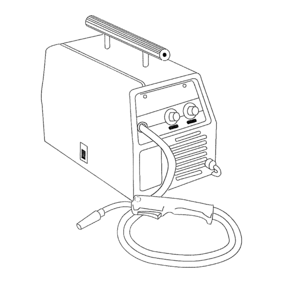
Page 8: Welder Specifications
DESCRIPTION represents the maximum welding time allowed. The balance of the 10-minute Your new wire feed welder is designed cycle is required for cooling_ for maintenance and sheet metal Your new welder has a duty cycle rating fabrication. The welder consists of a of 20% at the rated output. -
Page 9: Welder Installation
EXTENSION CORDS POWER SOURCE CONNECTION For optimum welder performance, extension cord should not be used POWER REQUIREMENTS unless absolutely necessary,. necessary, care must be taken in This welder is designed to operate on a selecting an extension cord appropriate properly grounded 120 Volt, 60 Hz, for use with your specific welder. -
Page 10: Install The Shielding Gas
IMPORTANT - GAS CYLINDER SIZE Align the tank tray bracket (1) to fit between the legs at the back of the RESTRICTION! The tank tray you have cart (2) (as shown in Figure 2) so just installed on the back of tile welder that the mounting holes are aligned will handle gas cylinders... -
Page 11: Check The Gas Flow
Slowly crack open the cylinder valve, then turn open ALL THE WAY. Pull the trigger on the gun to allow the gas to flow.. KEEP THE TRIGGER PULLED. Listen and feel for gas flowing from the end of the welding gun. -
Page 12: Neoprene Drive Roller
5. Slide the roller onto the shaft so that If there is wire already installed the welder, roll it back onto the wire the groove in the roller lines up with spool by hand-turning the spool the inlet tube and the welding counter-clockwise. - Page 13 2. Make sure the proper groove the drive roller is in place for the wire being installed, if the proper groove is not in place, change drive roller as described above, Unwrap the spool of wire then find the leading end of the wire (it goes Motor Shat{...
- Page 14 direction. If this should happen, wire could feed inside the cable casing or take a right angle and follow the wires and gas hose inside welder. It could also feed back on itself jamming up the mechanism. Line the wire up in the inside groove of the drive roller, then...
-
Page 15: Set The Wire Drive Tension
20_ Installthe nozzle on the gun stainless steel, flux cored hardfacing assembly. For best results,coat the steel, and silicon bronze wetding insideof the nozzle with antFstick steel, select dc Reverse Polarity (dc + MIG). When using self-shielding, flux- spray or gel (part #4312, not core steel wire, use dc Straight Polarity supplied). -
Page 16: Operation
Position 4 on the Voltage Selector Operation of this welder consists produces the rated output of 90 amps, selecting and adjusting operating controls for optimum voltage (welding The duty cycle at 90 amps is 20%, but will increase as the heat setting heat) and wire speed settings decreased. -
Page 17: Maintenance
GENERAL This welder has been engineered to give WARNING many years of trouble-free service providing that a few very simple steps are taken to properly maintain ELECTRIC SHOCK CAN KILL! To reduce the risk of electric shock, always 1_ Keep the wire drive compartment unplug the welder from its ac power closed at all times... - Page 18 Live Wire Conduct.or Terminal Plastic Cable Tie Valve Tube Insulation Cable Hose Cable Hose Fitting internalStar Switch Lockwasher Handle Head End Case Gun Liner Gun Assembly Figure gun assembly can be laid out Tools Required: straight on a table or workbench •...
-
Page 19: Maintaining The Contact Tip
Pull the liner out of the cable Make sure the cable covering covering (tubing) from the handle (tubing) is far enough in the end and push the small piece of machine so that it is covered by the liner out of the conductor tube wire-feed torch... -
Page 20: Preventive Maintenance
TESTING FOR A SHORTED For best results, coat the inside of a new NOZZLE or freshly cleaned nozzle with anti-stick spray or gel Arcing between the nozzle and the work 1. Stop welding and clean any piece ALWAYS means the nozzle is accumulated slag or spatter from shorted,... - Page 21 Table 3. Troubleshooting TROUBLE POSSIBLE CAUSE POSSIBLE REMEDY .,,,,, ......Dirty, porous brittle 1. Plugged welding nozzle 1. Clean or replace nozzle weld 2 No shielding gas 2 Tank empty, flow restricted, or regulator set too tow 3, See SELECTING SHIELDING &...
-
Page 22: Schematic
< Model 205111 © © t_rr kL__. CO© kl.l < © >-... - Page 23 Model 205111 _IlHM rr" <...
-
Page 24: Replacement Parts List
Model 205111... - Page 25 ITEM DESCRIPTION PART NO, 117-076-002 ¥ 20511 Sears 90 amp MIG Welder Heat Control Switch 242-422-666 216-100-666 410_900-010 Front Panel 541_057-666 Strain Relief 238-223-666 Cable Assembly Knob 246-107-666 238-592_000 6' MfG gun Control Panel 4t0-868-040 880-418-666 Wire Speed control W/Circuit Board Transformer 880-410-666...
- Page 26 For the repair or replacement parts you need delivered directly to your home Call 7 am - 7 pro, 7 days a week 1-800-366-PART (1-800-366-7278) For in-home major brand repair service Call 24 hours a day, 7 days a week 1-800-4-REPAIR (1-800-473-7247) The model...
Need help?
Do you have a question about the 934.205111 and is the answer not in the manual?
Questions and answers