Table of Contents
Advertisement
Quick Links
SWAINS
[ IIFTSMIIN+
MODEL NUMBER 917.251471
OWNER'S
MANUAL
+ Assembly
• Operation
• Customer Responsibilities
+ Service and Adjustments
+ Repair Parts
CAUTION:
Read
and follow
all safety
rules and instructions
before operating
this equipment.
FOR CONSUMER
ASSISTANCE
HOT LINE, CALL THIS TOLL FREE NUMBER:
1-800-659-5917
Advertisement
Table of Contents

Related Manuals for Craftsman 917.251471


Summary of Contents for Craftsman 917.251471
- Page 1 SWAINS [ IIFTSMIIN+ MODEL NUMBER 917.251471 OWNER'S MANUAL + Assembly • Operation • Customer Responsibilities + Service and Adjustments + Repair Parts CAUTION: Read and follow all safety rules and instructions before operating this equipment. FOR CONSUMER ASSISTANCE HOT LINE, CALL THIS TOLL FREE NUMBER: 1-800-659-5917...
- Page 2 SAFETY RULES Safe Operation Practices for Ride-On Mowers IMPORTANT: THIS CUTTING MACHINE IS CAPABLE OFAMPUTATING HANDS AND FEET AND THROWING OBJECTS. FAILURE TO OBSERVE THE FOLLOWING SAFETY INSTRUCTIONS COULD RESULT IN SERIOUS INJURY OR DEATH. GENERAL OPERATION III. CHILDREN Read, understand, and follow al! instructions in the manual Tragic accidents can occur if the operator...
- Page 3 LIMITED TWO YEAR WARRANTY ON CRAFTSMAN RIDING EQLIIPMENT For two (2) years from the date el purchase, if this Craftsman Riding Equipment is maintained ubricated and tuned up according to the instructions _n the owner's manual Sears will repair or replace, free of charge, any parts found to be defective in material or workmanship.
-
Page 4: Table Of Contents
TABLE OF CONTENTS SAFETY RULES ............OPERATION ............10=14 PRODUCT SPECIFICAT_ONS ........MAINTENANCE SCHEDULE ........CUSTOMER RESPONSiBILiTIES ..... 3. 15-19 SERVICE AND ADJUSTMENTS ......20-25 WARRANTY ..............STORAGE ..............TABLE OF CONTENTS ..........TROUBLESHOOTING ........... 27-28 iNDEX ................REPAIR PARTS - TRACTOR ........ 30-47 TRACTOR ACCESSORIES .......... -
Page 5: Accessories
ACCESSORIES AND ATTACHMENTS These accessories and attachments were available through most Sears retail outlets and service centers when the tractor was purchased. Most Sears stores can order these items for you when you provide the model number of your tractor. ENGINE MAINTENANCE _,RKPLUG... - Page 6 CONTENTS PACK Parts packed separately in carton Parts Bag contents shown full size Seat (t) Shoulder Bolt 5 16-18 (1) HexBolt _/2-13xl (1) Lock Washer Steering Video Wheel Cassette Manua, Parts Bag 11) Washer 17/32 x 1-3/16 x 12 Gauge Parts bag contents not shown full size Steering...
- Page 7 ASSEMBLY Your new tractor has been assembled at the factory with exception of those parts left unassembled for shipping purposes. To ensure safe and proper operation of your tractor all parts and hardware you assemble must be tightened securely. Use the correct tools as necessary to insure proper tightness.
- Page 8 ASSEMBLY Inspection for corrosion, (See Fig. 3) iNSTALL SEAT Testing battery, Adjust seat before tightening adjustment boll Jumping (if requiredL Remove cardboard packing on seat pan, Periodic charging. Place seat on seat pan and assemble shoulder bolt. LOCK Assemble adjustment bolt. lock washer and flat washer FLAT HEX NUT WASHER...
- Page 9 ASSEMBLY INSTALL MOWER AND DRIVE BELT (See Place the suspension arms on outward pointing deck pins. If necessary, rock and raise front of mower to Figs. 4 and 5) align deck _ins with the holes in suspension arms, Be sure tractor is on level surface and mower suseenslon Retain with double loop retainer springs.
- Page 10 ASSEMBLY J CHECKLIST BEFORE YOU OPERATE AND ENJOY YOUR NEW TRACTOR. WE WISH TO ASSURE THAT YOU RECEIVE THE BEST PERFORMANCE AND SA TISFACTION FROM THIS QUALITY PRODUCT. PLEASE REVIEW THE FOLLOWING CHECKLIST: v" All assembly instructions have oeen completed. v"...
- Page 11 OPERATION These symbols may appear on your tractor or in literature supplied With the product. Learn and understand their meaning. Ez3& BATTERY CAUTION OR REVERSE FORWARD FAST SLOW WARNING ENGINE ON ENGINE OFF OIL PRESSURE CLUTCH LIGHTS ON LIGHTS OFF CHOKE MOWER HEIGHT DIFFERENTIAL...
- Page 12 OPERATION KNOW YOUR TRACTOR READ THiS OWNER'S MANUAL SAFETY RULES BEFORE OPERATING YOUR TRACTOR Compare the illustrations with your tractor to familiarize yourself with the locations of various controls and adjustments. Save this manual for future reference. IGNITION SWITCH CHOKE THROTTLE CONTROL CONTROL...
- Page 13 OPERATION _ ore resul_W lie operating YOUr tract_ViSionsafetymask r the spectacles or standard safety glasses. CAUTIO. trao -om- -1 HOW TO USE YOUR TRACTOR ,_ _ _dabo.ve , before lear= position; to empty (See Fig. 6) TO SET PARKING BRAKE grass catcher, etc, Your tractor is equipped with an o0erator presence sensing...
-
Page 14: Carburetor
OPERATION Move gearshift lever to 1st gear, Be sure you have (See Fig. 7) TO OPERATE MOWER allowed room for tractor to roll slightly as you restart Your tractor is equipped with an operator presence sens- movement. ing switch. Any attempt by the operator to leave the seat To restart movement, slowly release parking brake and with the engine running end the attach ment clutch engagee clutch/brake pedal. - Page 15 OPERATION MOWING TIPS (See Fig. 7) TO START ENGINE Tire chains cannot be used when the mower housing is When starting engine for the first time or if engine has run attached to tractor. out of fuel. it will take extra cranking time to move fuel from the tank to the engine.
- Page 16 CUSTOMER ;IBIL TIES I - Change more often when operanng under a heavy moaoor #nn_gh ambient temDera_ures. 5 - If equipped with adjustable system 2 - _erstce m _re often when operating in dirty or dusty conditions 6 - Not reauired if e_UIDDe(3W_tl malRtensnce4ree battery 3 - li _]l ooed with oil f_lter change oil every 50 hour._...
- Page 17 CUSTOMER RESPONSIBILITIES TO SHARPEN BLADE (See Fig. 10) TRACTOR Care should De taken to keep the blade balanced. Always observe safety rules when performing any mainte- unbalanced blade will cause excesswe vibration and even - nance. tuat damage to mower and engine, •...
- Page 18 CUSTOM LINES V_BELTS AIR SCREEN Check V-belts for deterioration and wear after 100 hours of operation and replace if necessary, The belts are not adjustable. Replace belts if they begin to slip from wear. TRANSAXLE COOUNG KeeD transaxle free from build-urJ of dirt and chaff which can restrict cooling.
- Page 19 CUSTOMER RESPONSIBILITIES MUFFLER IMPORTANT: PETROLEUM SOLVENTS SUCH KEROSENE. TO BE USED TO CLEAN inspect and replace corroded muffler and spark arrester (if CARTRIDGE, THEY MAY CAUSE DETERIORATION equipped) as it could create a fire hazard and/or damage. THE CARTRIDGE. DO NOT OIL CARTRIDGE. DO NOT PRESSURIZED CLEAN...
- Page 20 ERVlCE ADJUSTMENTS CAUTION: BEFORE PERFORMING ANY SERVICE OR ADJUSTMENTS: Place gearshift lever in neutral IN) position. Depress clutch/brake pedal futly and set parking brake. Place attachment clutch in "DISENGAGED" position. Turn ignition key "OFF" and remove key. Make sure the btsdes and aH moving parts have completely stopped, Disconnect spark plug wire from spark plug and place wire where it cannot come in contact with...
-
Page 21: Side-To-Side
SERVICE AND ADJUSTMENTS TO REPLACE MOWER DRIVE BELT NOTE: Each full turn of adjustment nut will change mower qeight about 3/16". MOWER DRIVE BELT REMOVAL (See Fig. 20) - Recheck measurements after adjusting. Park tractor on a level surface, Engage parking brake. Disengage attachment clutch control. - Page 22 WITH PARKING BRAKE "ENGAGED" Check secondary idler arm and idler to see that they rotate freely. Be sure sefing is hooked in secongary idler arm ant sway-bar bracket. Install new belt in lower groove of L.P mandrel pulley, idler pulley: and center mandrel pulley as shown. Roll belt over R.H.
- Page 23 ADJUSTMENTS SERVICE AND TO REMOVE WHEEL FOR REPAIRS TRANSAXLE SHIFTER LINKAGE AND AD- (See Fig, 26) JUSTMENT (See Figs. 24 and 25) Block up axle securely, The transaxle should be in neutral when the gear shift lever is in the neutral (N) (lock gate) position. The adjustment is Remove axle cover, retaining ring and washersto allow preset at the factory;...
- Page 24 SERVICE AND ADJUSTMENTS _HOOO HEADLIGHT "POSITIVE" "NEGATIVE" WIRE CONNECTOR IL°PANE;! FIG. 28 ENGINE FiG. 27 TO ADJUST THROTTLE CONTROL CABLE (See Fig. 29) _'O REPLACE HEADLIGHT BULB The throttle control has been preset at the factory and Raise hood. adjustment should not be necessary. Check adjustment as Pull bulbholderoutoftheholeinthebacksideofthe described below before loosening cable.
- Page 25 ADJUSTMENTS SERVICE AND While still holding throttle lever against idle speed With engine not running, move choke control (located screw, turn idle mixture screw in (clockwise) until on dash panel) to full choke (N) position. engine begins to die and then turn out _counterclock _ Remove air cleaner cover, filter and cartridge plate to wise) until engine runs rough.
-
Page 26: Cleaning
STORAGE ENGINE Immediately prepare your tractor for storage at the end of the season or if the tractor will not be used for 30 days or more. FUEL SYSTEM IMPORTANT: IT IS IMPORTANT TO PREVENT the tract_ with" DEPOSITS FROM FORMING ESSENTIAL :UEL... - Page 27 TROUBLESHOOTING POINTS CORRECTION CAUSE PROBLEM Fill fuel tank. Out of fuel. Will not start See "TO START ENGINE" in Oeeratlon section. Engine not "CHOKED" properly. Wait several minutes before attempting to start. Engine floode¢ Reolace seark plug, Bad sparkplug. Clean/feE ace air fitter. Dirty air filter.
- Page 28 TROUBLESHOOTING POINTS PROBLEM CAUSE CORRECTION Engine continues to run Faulty operator-safety presence control system. Ch_ck wiring, sw_[cne,o and connect=ons. If not .orJected contact an authorized service center/ when operator Ieaves seat with attachment clutch delver[merit. engaged Worn bent or loose blade Poor - uneven Rec ace blade...
- Page 29 TRACTOR -- MODEL NUMBER 917.251471 SCHEMATIC BLACK BATTERY © FUSE 30 AMP. STARTER BLACK MMETER WHITE © SOLENOID CLUTCH BRAKE (PEDAL UP) WHITE SEAT SWITCH • (NOT OCCUPIED LACK BLAC_ (CLUTCH OFF, CONNECTOR ,GN, ,ON SPARK SLACK UNIT PLUGS O------_ CHARGING SYSTEM OUTPUT...
- Page 30 REPAIR PARTS TRACTOR - - MODEL NUMBER 917.251471 ELECTRICAL...
- Page 31 144921 Switch Ign 3 pos 140400 Nut Ignition 141226 Cover Sw Key BIk 1 25 Text SLT 140403 Key Ign Molded Craftsman Delta 110712X Switch Light BIk BIk Red 108236X Bracket Switch Clutch STD601005 Screw Tap Hex #10-24unc X 1/2...
- Page 32 REPAIR PARTS TRACTOR -- MODEL NUMBER 917.251471 CHASSIS _o.J 4 •...
- Page 33 REPAIR PARTS TRACTOR - - MODEL NUMBER 917.251471 CHASSIS PART DESCRiPTiON 151169 Chassis Weldment 140356 Draw Bar 17490612 Screw Thdrol. 3/8-16 x 3/4 Ty-tt 145206 Saddle t26471X Clip Insulated 145203 Dashboard STD533710 Bolt Carriage 3/8-!6 x 1 145222 Panel Dashboard LH 145221 Panel Dashboard RH 136673X574...
- Page 34 REPAIR PARTS TRACTOR - = MODEL NUMBER 917.251471 DRIVE 42 5! . - :" 26_^ 47 ,._._...
- Page 35 REPAIR PARTS TRACTOR - = MODEL NUMBER 917.251471 DRIVE PART PART DESCRIPTION DESCRIPTION 138788 Link. Clutch Transaxle. Peerless. 6 Speed, 105710X Model Number 820-016B 126471X Clip, Fuel Line t10422X Spring, Brake Return 105709X Spring, Return. Clutch 121327X Bolt. Fin Hex 3/8-16 UNC x 1-1/4 Pulley, Transaxle STD523712 STD582075...
- Page 36 REPAIR PARTS TRACTOR =- MODEL NUMBER 917.251471 ASSEMBLY STEERING -< ,../ • / " ¢.. /" 34//...
- Page 37 REPAIR PARTS TRACTOR - - MODEL NUMBER 917.251471 STEERING ASSEMBLY PART PART DESCRIPTION DESCRiPTiON Bracket Pvt Ma CI Lvr 139768 Wheel Steering Ayp/kelch BIk 138171 Tie Roc 142033 Axle Asm Fr LT 139929 Washer 11/32 x 3/4 x 16 Ga. 135227 SpindleAsmLH 19111216...
- Page 38 REPAIR PARTS TRACTOR - - MODEL NUMBER 917.251471 ENGINE OPTIONAL EQUIPMENT Spark Attester...
- Page 39 REPAIR PARTS TRACTOR = - MODEL NUMBER 917.251471 ENGINE PART DESCRIPTION Control Throt RH BIk Pdl 36 60 132755 Screw Hex Thd Cut 1 _4-20x5/8 T 17720410 150469 Engine B&S, 20 HP. Model No 460777. Type Number 1297-01 Muffler Asm Twin Lo-Tone 149723 Exhaust Asm RH B&S 18 HP Vert 144068...
- Page 40 REPAIR PARTS TRACTOR - - MODEL NUMBER 917.251471 SEAT ASSEMBLY 14.. "b. 1" . 2_3" "12 PART PART DESCRIPTION DESCRIPTION 124238X Seal Cap Spring Seat 140122 153236 Bolt Shoulder 5/16-18 Unc Blkz-2A BracKet Pnt Pivot Seat (blk) 140551 STD541431 Nut Lock Hex W/Ins 5/16-18 145006 Clio Push-In 74780814...
- Page 41 Decal. V-belt Dr Sch Tractor E Decal. Dash Instruction Operat Eng 151696 151695 Decal, Grille Lawn Tractor Dov Decal. Chassis 6 Sp 44" 151693 Decal. Hood Rh Craftsman 139346 Decal. Mower Drive Schematic 151694 140837 Decal, Hood Lh Craftsman Decal. Saddle Brake Parking...
- Page 42 REPAIR PARTS TRACTOR == MODEL NUMBER 917o251471 MOWER LiFT c". _-" -...
- Page 43 REPAIR PARTS TRACTOR - - MODEL NUMBER 917.251471 MOWER LIFT PART DESCRiPTiON 121006X Rod. Lever Shaft. Lift 140673 Bolt Hex 3/8-t6 x 1-1/2 74780624 125631X Grip, Handle 122365X Sutton. Plunger 122364X Plunger, Lever 2876H Spring Link. Lift. LH 145537 145536 Link, Lift.
- Page 44 REPAIR PARTS TRACTOR - ° MODEL NUMBER 917.251471 MOWER DECK q?'_.-72 _::_70...
- Page 45 REPAIR PARTS TRACTOR = = MODEL NUMBER 917.251471 MOWER DECK PART PART DESCRIPTION DESCRIPTION Cover. Mandrel RH 140579 Deck Asm.. Mower 44" Vented 137200 Screw Thd Roll 1/4-20 x 5/8 STD541431 Nut Crewnlock 5/16-18 137729 Cover. Mandrel LH STD533107 Bolt. Carriage 5/16-18 x 3/4 136574 Runner.
- Page 46 REPAIR PARTS TRACTOR -- MODEL NUMBER 917.251471 PEERLESS TRANSAXLE - MODEL NUMBER 1t20-0t lib...
- Page 47 REPAI R PARTS TRACTOR - = MODEL NUMBER 917.251471 PEERLESS TRANSAXLE o MODEL NUMBER 820=016B REF PART REF PART NO, NO. DESCRIPTION NO. NO. DESCRIPTION Spur Gear. Steel. 22 Teeth (5.) 794513 Transaxle. Complete 778203A 772098A Transaxle Cover 778273 Spur Gear. Steel. 19 Teeth (6.) Spur Gear.
- Page 48 REPAIR PARTS TRACTOR - - MODEL NUMBER 917o251471 ENG)NE B&S - MODEL NUMBER 460777, TYPE NUMBER 1297-01 21_A...
- Page 49 REPAIR PARTS TRACTOR - = MODEL NUMBER 917.251471 ENGINE B&S - MODEL NUMBER 460777, TYPE NUMBER 1297-01 (358GASKET SET] [861 PUMP REPAIR KITI 121 CARBURETOR OVERHAUL...
- Page 50 REPAIR PARTS TRACTOR - - MODEL NUMBER 917.25t 4'71 ENGINE B&S - MODEL NUMBER 460777, TYPE NUMBER 1297-01 615A t16A O 81_A g _06-d _ 2"8 r 73...
- Page 51 REPAIR PARTS TRACTOR - _ MODEL NUMBER 917.2514,71 ENGINE B&S = MODEL NUMBER 450777, TYPE NUMBER 1297-01 615B...
- Page 52 REPAIR PARTS TRACTOR o - MODEL NUMBER 917.251471 ENGINE 8&S _ MODEL NUMBER 460777, TYPE NUMBER 1297-01 KEY PART KEY PART NO. NO° DESCRIPTION NO, NO. DESCRiPTiON Screw. Seres. Carburetor Mounting 498583 Cylinder Assembly 93970 Screw. Seres. 397265 Bearing, Cylinder 93208 *Seai Intake Manifold Mounting...
- Page 53 REPAIR PARTS TRACTOR -- MODEL NUMBER 917.251471 ENGINE B&S - MODEL NUMBER 460777, TYPE NUMBER 1297-01 KEY PART KEY PART NO. NO. DESCRIP'RON NO. NO. DESCRiPTiON 94297 Screw. Pan Head 615A 94900 Retainer. E-Ring 491297 615B 263080 Retainer Lever Assembly, Governor 223882 Washer.
- Page 54 SERVICE NOTES...
- Page 55 SUGGESTED GUIDE FOR SIGHTING SLOPES FOR SAFE OPERATION ONLY RIDE UP AND DOWN HILL, "" NOT ACROSS HILL SIGHTING GUIDE SIGHT AND HOLD THiS LEVEL WITH SKY LINE OR TREE. 15 ° MAX. greater than 15°), never across the face. Make turns gradu- Operate your Tractor up and down the face of slopes (not...
-
Page 56: Replacement
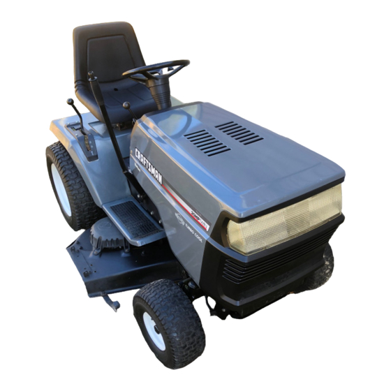
£RAFTSMI:IN ® OWNER'S 20.0 HP MANUAL ELECTRIC START 44" MOWER 6 SPEED TRANSAXLE GARDEN TRACTOR MODEL NO. Each tractor has its own model number. Each engine has its own model number. 917.251471 The model number for your tractor will be found on the model plate located under the seat.
Need help?
Do you have a question about the 917.251471 and is the answer not in the manual?
Questions and answers