Table of Contents
Advertisement
Available languages
Available languages
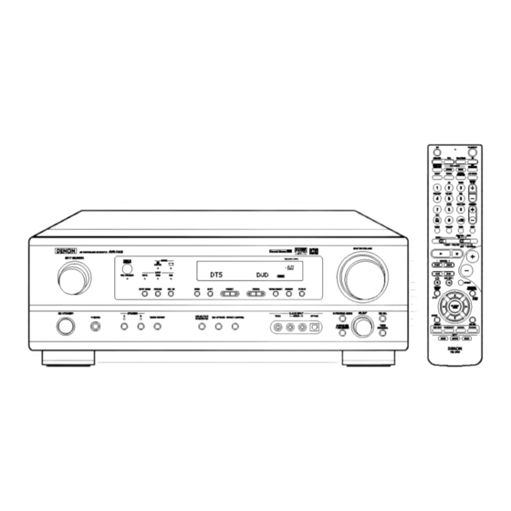
AV SURROUND
RECEIVER
AVR- 1603/683
OPERATING INSTRUCTIONS
MODE D'EMPLOI
.---
,7
--
.-
DTS
DUD
O
©©©
©©©
©
©
FOR ENGLISH READERS
PAGE
2 -
PAGE
53, 104 ~ I08
•
We greatly appreciate
your purchase of this unit.
•
TO be sure you take maximum
advantage
of all the
features this unit has to offer, read these instructions
carefully and use the set properly. Be sure to keep this
manual
for future reference
should any questions
or
problems
arise.
"SERIAL
NO.
PLEASE
RECORD
UNiT
SERIAL
NUMBER
ATTACHED
TO
THE REAR OF THE CABINET
FOR FUTURE
REFERENCE"
POURLESLECTEURSFRANCAIS
PAGE
2,54-
PAGE
108
•
NOUS vous remercions pour I'achat de cet appareiL
•
Pour _tre s_r de profiter
au maximum
de toutes
les
cerect6ristiques
qu'offre cet appareil, lire avec soin ces
instructions
et
bien
utiliser
I'appareiL
Toujours
conserver
ce
mode
d'emploi
pour
s'y
r6f_rer
ult6rieurement
en cas de question ou de probl_me.
"NO. DE SERIE
PRIERE DE NOTER
LE NUMERO
DE SERIE DE L'APPAREIL
tNSCRIT
A L'ARRIERE DU COFFRET DE FA(_ON A POUVOIR
LE CONSULTER
EN CAS DE PROBLEME."
Advertisement
Table of Contents

Related Manuals for Denon AVR-1683


Summary of Contents for Denon AVR-1683
- Page 1 AV SURROUND RECEIVER AVR- 1603/683 OPERATING INSTRUCTIONS MODE D'EMPLOI .--- © © ©©© ©©© FOR ENGLISH READERS PAGE PAGE 53, 104 ~ I08 POURLESLECTEURSFRANCAIS PAGE 2,54- PAGE • We greatly appreciate your purchase of this unit. • NOUS vous remercions pour I'achat de cet appareiL •...
- Page 2 • SAFETY PRECAUTIONS CAUTION TO PREVENT ELECTRIC SHOCK, MATCH WIDE BLADE OP PLUG TO WIDE SLOT, FULLY INSERT. ATTENTION CAUTION: TO REDUCE THE RISK OF ELECTRIC SHOCK, DO NOT REMOVE COVER (OR BACK)= NO POUR EVITER LES CHOCS ELECTRIQUES, INTERODUIRE USER-SERVICEABLE PARTS INSIDE.
-
Page 3: Safety Instructions
SAFETY INSTRUCTIONS Read Instructions - All the safety and operating instructions Power-Cord Protection - Power-supply cords should be routed should be read before the product is operated. so that they are not likely to be walked on or pinched by items placed upon or against them, paying particular... -
Page 4: Before Using
• INTRODUCTION Thank you for choosing the DENON AN Surround receiver. This remarkable component has been engineered to provide superb surround sound listening with home theater sources such as DVD, as well as providing outstanding high fidelity reproduction of your favorite music sources. - Page 5 DENON remote controllable AV components as well as for LD extending to 20 kHz, the same as the range of CDs, thus resulting players, video decks, TVs, etc., of other major manufacturers in clearer, more richly expressive sound.
-
Page 6: Part Names
PART NAMES AND FUNCTIONS • For details on the functions of these parts, refer to the pages given in parentheses TONE CONTROL button ............{31) Power operation switch ..........(18, 29, 45) Headphones jack {PHONES} ............ {32) CH VOL button ................ {35) INPUT MODE button ........... - Page 7 • For detaiEs on the functions of these parts, refer to the pages given in parentheses ......(,6_ I LED {indicator) ......(25, 28) ..iPO_ER0°ttons .....82_.01 i OlRE_r SURROUND _'1 _I_REO i(ZD (ZD (ZD (ZD :-_"_" C_" .."PJRFA"...
-
Page 8: Read This First
READ THIS FIRST This AV Surround Receiver must be setup before use. Following these steps. "_-o_ep (page 8 to 15) Choose the best location to setup the Speakers and connecting the components. Step 2 (page 16) Next, insert the batteries into the remote control unit. Step 3 (page 17 to 23) - Page 9 CONNECTIONS • Do not plug in the power cord until all connections have been • Note that binding pin plug cords together with power cords or completed. placing them near a power transformer will result in generating • Be sure to connect the left and right channels properly (left with hum or other noise.
-
Page 10: Monitor Out
To connect the video signal, connect using a 75 £2/ohms video signal cable cord. Using an improper cable can result in a drop in sound quality. TV or DBS tuner I Connecting a TV/DBS tuner MONITOR • Connect the TV's video input iack {VIDEO iNPUT) to the MONITOR •... - Page 11 [Connecting a Video game equipment Video game • Connect tile Video ganle equipment's output iacks to this unit's V AUX INPUT iacks [ Connecting a Video camera equipment Video camera • Connect the video camera equipment's output jacks to this unit's V AUX INPUT iacks [ --OUTP T ®®...
- Page 12 • When making connections, also refer to the operating instructions of the other components. • The signals input to the color difference (component) video jacks are not output from the VIDEO output jack (yellow) or the S-Video output jack. )n addition, the video signals input to the VIDEO input (yellow) and S-Video input jacks are not output to the color difference (component) video jacks.
- Page 13 DIRECTION BROADCASTING STATION FM ANTENNA 75 _2/ohms COAXIAL @,,. CABLE D=-' @._ •@ @,_ @@l= •.,@@, _:_@_ AM OUTDOOR ANTENNA .@ @.. @ _;= ///_ ///// FM INDOOR ANTENNA GROUND (An Accessory) AM loop antenna assembly Connection of AM antennas antenna terminals 1 Push the [ever...
-
Page 14: Speaker Systems
• Connect speaker terminals with the speakers making sure that like Speaker Impedance polarities are matched ((_ with (_, _ with 8) Mismatching of polarities will • When speaker systems A and B are use separately, speakers with result in weak central sound, unclear orientation of the various instruments, _mpedance of 6 to 16 _dohms can be connected for use as front speakers... - Page 15 If the protection circuit is activated again even though there are no problems with the wiring or the ventilation around the unit, switch off the power and contact a DENON service center. • The protector circuit may be activated if the set is played for long periods of time at high volumes when speakers with an impedance lower than the specified impedance (for example speakers with an impedance of lower than 4 _/ohms) are connected.
-
Page 16: Using The Remote
UNIT USING THE REMOTE CONTROL Following the procedure outlined below, insert the batteries before using the remote control unit. Point the remote control unit at the remote control sensor as shown on the diagram at the left. NOTES: • The remote control unit can be used from a straight distance of approximately 23 feet/7 meters, but this distance will shorten or... - Page 17 SETTING UP THE SYSTEM • Once aft connections with other AV components have been completed as described in "CONNECTIONS" (see pages 9 to 15), make the various settings described below on the display. These settings are required to set up the listening room's AV system centered around the this unit.
- Page 18 Check that all the components are correct, then press the POWER operation switch on the main unit or the POWER button on the remote control unit to turn on the power. (Main unit) {Remote control unit) Press the SYSTEM SETUP button to enter the setting. sETup :+::iii;'.,.':iii;T EN :iii;...
- Page 19 NOTE: • When "Small" has been selected for the front speakers, "Large" cannot be selected for the surround speakers. t& Use the _ (left) and _ (right) buttons to select your subwoofer setting. (Initial) [ =::J" :iii: ==J...J 0 0 F:"Ei[J:i;: "? E :iii:] (left) button (right} button...
- Page 20 NOTES: -- Assignment of low frequency signal range -- • The signals produced from the subwoofer channel are LFE signals (during playback of Dolby Digital or DTS signals) and the low frequency signal range of channels set to "SMALL" in the setup. The low frequency signal range of channels set to "LARGE" are produced from those channels.
- Page 21 Use the _ {left) and _) (right) buttons to set the distance from the center speaker to the listening position. :iii: =..,..,"" E:" _...,m", ,..,...E:" _:::= i 2 "i:" " i. • The number changes in units of 1 foot each time one of the buttons is pressed. Select the value closest to the measured distance.
- Page 22 (OPTICAL 2) terminal. &/\\ Use the (left} and _ (right) buttons to assign the input function connected to the OPTICAL input 2 (Initial) I1,', II,,,:::R IIc,:: ,R i :2 0F'T:? (left} button {right) button Press the ENTER or _ (down} button to switch the auto surround mode setting.
- Page 23 _--_ Press the SYSTEM SETUP button to finish system set up. This completes the system setup operations. Once the system is set up, there is no need to make the settings again unless other components or speakers are connected to or the speaker layout is changed.
- Page 24 REMOTE CONTROL UNIT • Turn on the power of the different components before operating them. Set mode switch 1 to "AUDIO". /IUDIO• o_l[IEO m set mode switch 2 to the position for the component to be operated. (CD, CDR/MD or Tape deck) CD_"D_ _ Operate the audio component.
- Page 25 DENON and other makes of components can be operated by setting the preset memory. This remote control unit can be used to operate components of other manufacturers without using the learning function by registering manufacturer of the component as shown on the List of Preset Codes {pages 104-10B).
- Page 26 : Return SETUP : Setup P,, V <l, b* : Cursor up, down, left and right ENTER : Enter setting NOTE: • Some manufacturers different names for the remote control buttons, so also refer instructions DENON I_NON remote control that component.
- Page 27 DENON NOTES: • For this CD, CDR, MD and TAPE components, buttons can be operated in the same way as for Denon audio components (page 24). • The TV can be operated when the switch is at DVD/VDP, VCR, TV position.
- Page 28 • "Punch Through" is a function allowing you to operate the PLAY, STOP, MANUAL SEARCH and AUTO SEARCH buttons on the CD, TAPE, CDR/MD, DVD/VDP or VCR components when in the DBS/CABLE or TV mode. By default, nothing is set. Set mode switch 1 to "VIDEO".
-
Page 29: Operation
Press the SPEAKER A or B button to turn the speaker on. Xa_Ft 8FE_R ®00--_ {Main unit) {Remote control u_it} • The front speaker A, B setting can be also be changed with the SPEAKER button on the remote control unit. DENON... - Page 30 C _D Select the input source to be played. Example: CD h,_rr ELr_11=_ (Main unit} (Remote control unit) Select the input mode. • Selecting the analog mode Input mode selection function Press the ANALOG button to switch to the analog input. Different input modes can be selected for the different input sources.
- Page 31 Input mode display of these Hghts, depending on the Select the play mode. • in the AUTO mode inputsignal Press the SURROUND MODE button, then turn the SELECT knob. I_Pbr © Example: Stereo • in the DIGITAL PCM mode 8URROUNDMODE S_R_ _pLr_ AUTO...
- Page 32 NOTE: [2] Listening over headphones To prevent hearing loss, do not raise the volume level excessively when using headphones. PHONES Plug the headphones' plug into the jack. -_ Connect the headphones to the PHONES jack. The pre-out output (including the speaker output) is automatically turned off when headphones...
- Page 33 Set the external input (EXT. EXT, IN IN) mode. Press the EXT. iN to switch the external input. (Mainunit) (Remote control u nit} Once this is selected, the input signals connected to the FL (front left), FR (front right), C (center), SL (surround left), and - -- SR (surround right) channels of the EX_.
- Page 34 (Remote colltrol unit) NOTE: Please make sure "AUDIO" position of the slide switch on the remote control unit. After completing the adjustment, press the TEST TONE button again. _ST_NE {Remote c0ntlol unit} DENON...
- Page 35 • After adjusting using the test tone._ adjust the channel levels either according to the playback sources or to suit your tastes, as (described) below. Select the speaker whose level you want to adjust. (Main unit} (Remote control unit) The channel switches as shown below each time the button is pressed.
- Page 36 Display pARAMETER Pl_'_IM _ C: i F_:__-'!i'q._3 IH,::,DE (Main unit) {Remote control unit) DENON ec4_J To perform this operation from the remote control unit, check that the mode selector switch is set to "AUDIO". Select the optimum mode for the source.
- Page 37 Surround parameters Set the various surround parameters. Pro Logic 11 Mode: • CINEMA EQ setting The Cinema mode is for use with stereo television shows and all [ ..........programs encoded in Dolby Surround. L..EHLi'H'I _:/! Li_'t' The Music mode is recommended as the standard mode...
- Page 38 Select the input source. [ Playback with a digital input I _ Select an input source set to digital (COAXIAL!OPTICAL) (see page 21). Example: iNPlrr e_E_0_ [TJD/V_p {Main unit} (Remote control unit) i°o _2_Set the input mode to "AUTO" or DTS. INPUT MODE {Ivlaln unit} IRemote...
- Page 39 Use the _ (left) and _ (nght} buttons to set the D. COME (Initial} ....i":_ .. C:"EHi:::= .. OF::'F::" {Remote colltrol unit) (left) button (right) button SURROUND Press the SURROUND PARAMETER or _ (down) button to switch to the LFE setting. NOTE: {Remote c0_trol...
-
Page 40: Dsp Surround
DSP SURROUND SIMULATION • This unit is equipped with a high performance DSP (Digital Signal Processor) which uses digital signal processing to synthetically recreate the sound field. One of 7 preset surround modes can be selected according to the program source and the parameters can be adjusted according to the conditions in the listening room to achieve a more realistic, powerful sound. -
Page 41: Effect Level
• TO operate the surround mode and surround parameters from the remote control unit. Select the surround mode for the input channel. °'° (Remote control unit} The surround mode switches in the following order each time the DSP SIMULATION button is pressed: To enter the surround parameter setting mode, press the SURROUND PARAMETER button. -
Page 42: Delay Time
(3) DELAY TIME Use the _ {left} and _ (right} buttons to set the delay time. (Initial} ........_ {Remote corltrol unit) {left} button {right} button (4) D. COMP. Use the (_ {left} and _) (nght} buttons to set the D. COMR (Initial} {Remote corltrol... - Page 43 • Operating the surround mode and surround parameters from the main unit's panel. Turn the SELECT knob to select the surround mode. • __ oo {Main unit) 21,3 • When turned clockwise • When turned counterclockwise To select the surround mode while adjusting the surround parameters, channel volume or tone control, press the SURROUND MODE button then operate the selector.
- Page 44 • Surround modes and parameters Channel output When When playing When pFaying When playing pla¥_ng Dolby Mode FRONT L/R CENTER SURROUND Digital signalsDTS slgna_s ANALOGsignals WOOFER signals (96k) DIRECT © © © { ._}) © STEREO © © © { ._}) ©...
- Page 45 LISTENING TO THE RADIO This unit is equipped with a function for automatically searching for FM broadcast stations and storing them in the preset memory. When the main unit's power operation switch turn on while pressing the set's PRESET A button the unit automatically begins searching for FM broadcast stations.
- Page 46 Set the input source to "TUNER". oOool iNpjr _r_ '_JiqER {Mai/i unit) {Remote co/it/ol unit) Watching the display, press the BAND button to select the desired band (AM or FM}. C _OC _C ) {Maill unit} {Remote collttol unit} Press the MODE button to set the auto tuning mode. "-' '=_'_"-- O f ...J_.Ul'lrl_;.
- Page 47 Preparations: Use the "Auto tuning" or "Manual tuning" operation to tune in the station to be preset in the memory. Press the MEMORY button. © o°©o ° (Remote control unit} Press the SHIFT button and select the desired memory block (A to E).
- Page 48 LAST FUNCTION MEMORY • This unit is equipped with a last function memory which stores the input and output setting conditions as they were immediately before the power is switched off. • The unit is also equipped with a back-up memory. This function provides approximately one week of memory storage when the main unit's power switch is off and with the power cord disconnected.
- Page 49 ADDITIONAL INFORMATION Here we describe a number of speaker settings for different purposes. Use these examples as guides to set up your system according to the type of speakers used and the main usage purpose. (1) Basic setting Use this setting if your main purpose is to listen to movie music and when using one set (two speakers) of regular single-way or two-way...
- Page 50 • Dolby Digital Dolby Pro Logic Comparison of home surround systems Dolby Digital Dolby Pro Logic 51 ch 2 ch No recorded channels (elements) 51 ch 4 ch No playback channels Playback channels (max) L, R, C, SL, SR, SW L, R, C, S (SW _ recommended) Audio processing Digital discrete processing Dolby Digital (AC-3) encoding/decoding...
- Page 51 DTS DVDs. A DTS Digital Output logo is featured on the front panel of compatible DVD players. Recent DENON DVD player models feature DTS-compatible digital output - consult the player's owner's manual for information...
-
Page 52: Troubleshooting
TROUBLESHOOTING If a problem should arise,first check the following. 1. Are the connections correct ? 2. Have you operated the receiver according to the Operating Instructions 3. Are the speakers, turntable and other components operating property ? If this unit is not operating properly, check the items listed in the table below. Should the problem persist, there may be a malfunction. Disconnect the power immediately and contact your store of purchase. -
Page 53: Specifications
SPECIFICATIONS • Audio section • Power amplifier Front: 80 W + 80 W (8 _/ohms, 20 Hz - 20 kHz with 0.08% T.H.D.) Rated output: 110W+ 110W (6 o/ohms, 1 kHz with 0.7% T.H.D.) Center: 80 W (8 o/ohms, 20 Hz - 20 kHz with 0.08% T.H.D.) 110 W (6 o/ohms, 1 kHz with 0.7% T.H.D.) -
Page 54: Avant L'utilisation
• INTRODUCTION NOUSvous remercions d'avoir choisi I'ampli-tuner AN Surround de DENON. Ce remarquable composant a 6t6 fabrique pour fournir une superbe ecoute de sons d'ambiance avec des sources de cinema domestique telles que DVD, ainsi que pour assurer une formidable reproduction haute fidelite de vos sources musicales favorites. - Page 55 AV tel_commandables (sauf la chaine 0.1 pour les effets de basse fr@quence), la meme DENON comme les lecteurs disques laser, les platines video, les que celle des CD, offre un son plus clair et plus richement t_levisions, etc., d'autres...
- Page 56 NOMENCLATURE ET FONCTIONS • Pour les d6tails sur les fonctions de ces pieces, se reporter aux pages donnees entre parenth6ses ( }. Touche TONE CONTROL ............(81) Interrupteur de raise en marche ......... (68, 79, 95) Prise de casque d'6coute (PHONES) ........
- Page 57 • Pour les d6tails sur les fonctions de ces pieces, se reporter aux pages donn¢es entre parentheses ( }......I..I I LED flndicateur) ......(75, 78) ..ITouches POWER .....,,5_791 d'T°LC_hb,eSnce ....(81, 84, 86, 88, 91)t mltl_ SIIRmlIND _151_RNI i(ZD (ZD (ZD (ZD...
-
Page 58: A Lire En Premier
A LIRE EN PREMIER Ce r6cepteur d'ambiance AV doit _tre r6gl_ avant I'utilisation selon les 6tapes suivantes. Etape 1 (page 58 & 65) Choisir le meilleur emplacement pour I'installation des enceintes et la connexion des composants. Etape 2 (page 66) Ensuite, insurer les piles dans la t_16commande. - Page 59 CONNEXIONS • Ne pas brancher le cordon d'alimentation avant d'avoir termin_ • Remarquer que le groupement de cordons 8 fiches _ broche routes les connexiona. avec des cordons d'alimentation, ou le fair de les placer pros • Toujours connecter correctement los canaux de gauche et de d'un transformateur provoque un bourdonnement...
- Page 60 Pour connecter le signal video, connecter en utilisant un ceble de signal video de 75 £Z/ohms. L'utilisation d'un mauvais ceble pout entraher baisse de la qual[te du son. I Connexion d'un televiseur/tuner Prise de sortie de moniteur (MONITOR Televiseur/DB$ OUT) Televiseur ou tuner DBS •...
-
Page 61: Video Out
Jeu video EConnexion d'un jeu video • Connecter les iacks de sortie du jeu video au jacks V AUX INPUT de cet appareil Connexion d'un cam_scope Camescope • Connecter les iacks de sortie du carnescope au iacks V AUX INPUT de cet appareil --OUTPUT-- •... - Page 62 • Lors des connexions, se reporter 6galement aux instructions d'utilisation des autres composants. • Les signaux entres aux prises vid6o (composant) avec d[ff6rence de couleur ne sont pss sortis par la prise de sortie vid6o {VIDEO) (iaune) ou la prise de sortie vid6o S (S-VIDEO). De plus, les signaux video entres aux prises d'entree video (VIDEO) (jaune} et aux prises d'entree video S (S- VIDEO) ne sont pas sortis aux prises video (composant) avec difference de couleur.
- Page 63 DIRECTION STATION DE RADIODIFFUSION ANTENNE FM CABLE COAXIAL @@.- 75 _2/ohms D-'-, @._ ,,@@,- @@,_ •.,@@, EXTERIEURE AM ,,@@,. @ _;_ ///_ ///// Antenne int6rleure (Accessoire) TERRE Ensemble d'antenne-cadre Connexion antennes Connecter bomes d'antenne 1 Appuyer 2 IrLs6rer le 3 Ramener le levier conducteur levier...
- Page 64 • Connecter les bomes d'onceinte aux enceintes en respectant les polard6s {(_ Impedance d'enceinte au _, O au e) S[ les polarit6s nesont pas respectees, un son central faible • Lorsque sysf@mes d'enceinte A et sont utilises separement, est entendu, I'odentation des divers instrumonts n'est pas correcte et le sens...
- Page 65 I'appareil, couper I'aNmentation, et contacter un centre d'entretien DENON. • Le circuit de protection peut _tre active si I'appareil est utilis6 pendant une Iongue duree a un volume elev6 Iorsque des...
- Page 66 UTILISATION DE LA TI_LI_COMMANDE En suivant la procedure expliqu_e ci-dessous, inserer les piles avant d'utiliser la t_l_commande. Didger la tel6commande vers le detecteur de t61ecommande de la maniere indiquee sur le d[agramme de gauche. REMARQUES: • La telecommande peut etre util[see &...
-
Page 67: Installation
INSTALLATION DU SYSTEME • Une fois que toutes les connexions avec les autres composants AV ont ¢t_ faites comme indiqu¢ dans "CONNEXIONS" (voir pages 59 & 65), faire les diff_rents reglages d6crits ci-dessous sur I'affichage. Des r¢giages sont n6cessaires pour configurer le syst¢me de chambre d'_coute AV centr_ autour de cette unit&... - Page 68 V6rifier que tous les composants sont en ben ¢tat, puis appuyez sur I'interrupteur de raise en marche POWER sur I'unite principale ou la touche POWER sur la t_l¢commande pour allumer I'alimentation. (Unite princlpale) {Unit_ de t616commande) Appuyer sur la touche SYSTEM SETUP pour acc6der aux r6glages. sETup :+::iii;'.,.':iii;T Ei: H :iii;...
- Page 69 REMARQUE: • Lorsque I'option "Small" (petit) a 6t_ s_lectionn_e pour les haut-padeurs avants, I'option "Large" (grand) ne peut pas _tre s_lectionn_e pour les haut-parleurs centraux. Utiliser les touches (gauche) _ et (droit) _ pour selectionner le type de subwoofer installS. (Initial) touche (gauche)
- Page 70 REMARQUES: -- Attribution de la gamme de signaux de basse fr_quence -- • Les signaux produits d'un canal de subwoofer sont des signaux LTD (pendant la lecture de signaux Dolby Digital ou DTS) et la gamme de signal de basse frequence des canaux regles sur "SMALL" dans la configuration de la gamme de signaux de basse frequence des canaux regles aur "LARGE"...
- Page 71 Utifiser les touches {gauche) et (droit) pour r_gler la distance entre le haut-parleur central et le centre d'6coute. CEIN[EIR i 2 .i:i. • Le chiffre de distance change d'un pied (ft) _ chaque pression sur une des touches. Chois[r la valeur la plus proche de la distance mesur6e.
- Page 72 lii lilt,!'±1 i_[:t] _ [.'] OPTICAL 2 {OPTICAL 2). ('\\ Util[ser les touches (gauche) _ et (droit) _ pour attribuer la fonction d'entr_e connect6e a la borne d'entr_e (Initial) liT" II,cRII,::::,:::,R i :2 0F::'T:? 'iL. E touche {gauche) touche (droit) Appuyer sur la touche ENTER ou (bas) _ pour commuter le r6glage automatique...
- Page 73 _--_ Appuyer sur la touche SYSTEM SETUP pour terminer la configuration du syst_me. Ceci termine les op6rations de configuration du syst_me. Une fois la configuration termin6e, il n'est plus n_cessaire d'effectuer de changement sauf si un nouvel 616merit est ajout6 ou si la disposition des haut-parleurs est modifi_e.
-
Page 74: Unite De Telecommande
li=ilt,_±1 i_l[t] _ [.'] UNITE DE TELECOMMANDE • Mettre les diff_rents composants sous tension avant de les ut[l[ser. Regler le commutateur de mode 1 sur "AUDIO". ALIBI(] • o_l[_E0 m R_gler le commutateur de mode 2 8 la position du composant utiliser. - Page 75 DENON et d'autres fabdcants de composants peuvent _tre act[onn_s en reglant la m_moire pr6r6gl6e. La t_16commande peut 6tre utilisee pour faire fonctionner les composants d'autres marques sans utiliser la fonction d'apprentissage enregistrant la marque du composant comme indique sur la liste de codes pr6r¢gl_s (page 104-108).
- Page 76 lii lilt,!'±1 i_l:)] _ [.'] Regler le commutateur de mode 1 sur "AUDIO" ou "VIDEO". AUBIO • • _IBEO m _1- ,-L R_gler sur AUDIO pour la position CD, platine cassette CDR/MD, r6gler VIDEO pour position DVD/VDP, DBS/CABLE, VCR ou TV. Regler le commutateur de mode 2 sur le composant _ ut[l[ser.
- Page 77 DENON REMARQUES: • Pour ce composant CD, CDR, MD et TAPE, les touches peuvent _tre utilis_es de la m_me mani_re que pour les composants audio DENON (page 74). • Le t_l_viseur peut ¢tre utilise Iorsque le commutateur est en position DVD/VDP, VCR, TV.
- Page 78 • "Punch Through" (tension de p_n6tration) est une fonction permettant d'utiliser les touches PLAY, STOP, MANUAL SEARCH et AUTO SEARCH des composants CD, TAPE, CDR/MD ou VCR en mode DBS/CABLE ou TV. Le r6glage par d6faut est sur aucun composant. Regler le commutateur de mode 1 sur "VIDEO".
- Page 79 S61ectionner lea enceintes avant. Appuyer sur le commutateur d'enceinte A ou B pour activer I'enceinte. ®00--_ SPEAR {Unit# prlncipale} {Unit# de t616commande) • Le r_glage A, B de I'enceinte frontale peut 6galement _tre DENON modifi6 I'aide touche SPEAKER tel6commande.
- Page 80 C _D Selectionner la source d'entree a jouer. Exemple: CD WUT E_L_11_ (Unit6 princlpalel (U[lite de t#l@commande} Selectionner le mode d'entree. Fonction de selection de mode d'entr_e • Selection du mode analogique Differents modes d'entree peuvent etre selectionnes pour Appuyer sur la touche ANALOG pour passer &...
-
Page 81: Surround Mode
Affichage du mode d'entr_e S61ectionner le mode de lecture. Un de ceuxci s'al]ume selon ]e signal • En mode AUTO d'entr6e Appuyer sur la touche SURROUND MODE, puis tourner selecteur SELECT. _PLr_ Exemple: Stereo • En mode DIGITAL PCM 8URR(_JNDMODE Iri_REO _ptrr auto... - Page 82 REMARQUE: [2] Ecoute avec casque Afin d'eviter une perte de I'oui'e, ne pas augmenter excessive ment le niveau du volume Iors de I'udiisation d'ecouteurs. PHONES Brancher la fiche de casque darts la prise. -_ Connecter le casque _ la prise PHONES.
-
Page 83: Pre Out Subwoofer
Passer au mode d'entr6e EXT, IN externe (EXT. IN). Appuyer sur EXT. IN pour changerl'entr6e externe. (Unit6 prindpale) (Unit_ de t@ecommande) Une fois cette s61ection effectu6e, les signaux d'entr6e, connectes aux canaux FL {avant gauche), FR (arri¢re droit), C - -- (central), SL (surround gauche) et SR (surround... - Page 84 (U nit6 de t616commaade) REMARQUE: Veuillez vous assurer que le bouton 8 glissiere de la t616commande est en position "AUDIO". Apr_s la fin du r_glage, appuyer 8 nouveau sur la touche TEST TONE. _TONE {Unit# de t616commande) DENON...
- Page 85 • Apres le reglage utilisant les tonalit6s d'essai, ajuster les niveaux des canaux en fonction des sources de lecture ou selon votre convenance personnelle, comme decrit ci dessous. S61ectionner I'enceinte dont vous voulez ajuster le niveau. (Urfit6 principale} (Ur_it6 de t@l@commande} ke canal change de Is meni_re indiqu6e...
- Page 86 Selectionner la fonction se rapportant au composant que vous deskez ecouter. Exemple: © o.:: INPbT IEJC_DR _IVOP _c_:_ _ (Unit6 ptincipale) (Unite de t_lecommande) SGlectionner le mode Dolby Surround Pro Logic ]I. D(15YI DTS '_IJRROUND (__\ Le mode Dolby Surround Logic I1 Cinema ou Music peut _tre...
-
Page 87: Surround Parameter
REMARQUE: Regler les parametrages d'ambiance sonore. • Pendant le reglage des parametres, I'affichage va revenir B son • Reglage CINEMA EQ 6tat d'origine plusieurs secondes apres que le dernier bouton air 6te enfonce, ce qui terminera le reglage. [ ..........L..EH_:i'H'I _:._! Li_'t' Parambtres d'ambiance Mode Pro Logic 11:... - Page 88 S61ectionner la source d'entr6e. [ Reproduire avec une entr6e numerique] _} Selectionner une source d'entr6e r¢gl6e & num6rique (COAXIAL!OPTICAL) (voir page 71). Exemple: _IVDP INFLrr_ (Unit_ principale) (Unit6 de t616commande} @ R6gler le mode d'entr_e _ "AUTO" ou "DTS". INPUTMODE (Unit6 principale) (Unit6 de t616commande} S61ectionner le mode Dolby/DTS Surround.
- Page 89 Util[ser los touches (gauche) _ et (droit) _ pour r_gler la compression de la gamme dynamique (D.COMP). (Initial} IIH:i: I ....i":_ .. r:riHi:::' .. OF::F:: {U nit_ de t616commande) touche (gauche) touche (droit) SUHPOUND Appuyer sur la touche SURROUND PARAMETER ou (bas) _ pour passer au r6glage LFE.
- Page 90 lii lilt,_±1 i_l[t] _ [.'] SIMULATION D'AMBIANCE • Ce appareil est _quipe d'un DSP (processeur num_rique de signal) de haute precision qui utilise le traitement des signaux num6riques pour recreer de maniere synthetique le champ sonore. Un des 7 modes d'ambiance pr_r6gles peut 6tre s61ectionn6 en fonction de la source...
- Page 91 • Pour utiliser les modes surround et r_gler leurs param_tres a I'aide de la t616commande. S61ectionner le mode d'ambiance pour le canal d'entree. °'° (Unlt6 de t_l_commande) Le mode d'ambiance commute dans I'ordre suivant chaque fois que la touche DSP SIMULATION est enfoncee: Pour enter en mode de reglage de parametre d'ambiance appuyer sur ]a touche SURROUND...
- Page 92 (3) DELAY TIME Utiliser les touches (gauche} (_ et (droit) D pour r_gler le d61aL (Initial) ........_ {Unit_ de t616commande) touche (gauche} touche (droit) (4) D. COMP. Utiliser les touches (gauche} (_ et (droit) _) pour r_gler la compression de la gamme dynamique (D.COMP).
- Page 93 • Pour util[ser les modes surround et r_gler leurs param_tres a partir du panneau de commande de I'unit6 principale. Tourner le bouton SELECT pour s61ect[onner le mode surround. --'=°° (Unit# pri[icipale} 21,3 • Lorsqu'il est tourn6 darts le sens horaire •...
- Page 94 • Modes d'ambiance et parambtres So_ie canal En cas de Ep cas de En cas de reproduct on En cas de reproduction reproduction de s]gnau× rq 31Oducl]o_ de s[gnaux de sig_a_x de signaux Do,by Digital ANALOG Mode FRONT [JR CENTER SURROUND {96k} WOOFER...
- Page 95 ECOUTER DE LA RADIO Cet appareil est _quipe d'une fonction de recherche automatique d'emissions de radiodiffusion en FM et de leur stockage dans la memoire pr_r6glee. Lorsque I' interrupteur d'al[mentation de I'appareil principal est act[v_ en m_me temps que le touche de r_glage PRESET pFtEItET _, I'appareil commence...
- Page 96 liililt,]r±li_l:t]_[.,] R_gler la source d'entr6e sur "TUNER". oOool iNpjr _r_ '_JiqER (Unit6 principale} {Unit# de t61ecommande) En regardant I'affichage, appuyer sur la touche BAND {bande} pour s61ectionner la bande d6sir6e (AM ou FM). B/_ID K=UIID C )OC (Unlt6 principa]e} {Unit# de t616commande) Appuyer sur la touche MODE {mode) pour r6gler le mode de syntonisation automatique.
- Page 97 Preparatifs: Utiliser I'operation "Syntonisation automatique" "Syntonisation manuelle" pour syntoniser la station & pr6r6gler dans la m6moire. 9.:: Appuyer sur la touche MEMORY MI_tORY (m6moire). {Unit# de tel6commande) Appuyer sur la touche SHIFT, et s61ectionner le bloc de m6moire d_sir_ (A _ E}. SHIFT _@FT I_ _ _iU__...
- Page 98 lii lilt,!'±1 i_[:t] _ [.'] MEMOIRE DE DERNIERE FONCTION • Cet appareil est 6quip_ d'une m6mo[re de derni¢re fonction qui stocke les conditions des r_glages d'entr6e et de sortie telles qu'elles 6taient [mm6d[atement apr¢s la raise hers tension. • ['appareil est 6galement 6quip_ d'une m6moire de sauvegarde.
- Page 99 INFORMATIONS SUPPLEMENTAIRES Nous d6crivons ici un nombre de r6glages d'enceintes pour diff6rents buts. Utfliser ces exemples pour installer votre syst_me en fonction du type d'enceintes utifis6es et du principal objectif d'utilisation. (1) Reglage de base Utiliser ce reglage si votre principal objectif est d'ecouter la musique de film et en cas d'utilisation d'un ensemble (deux enceintes) de haut-...
- Page 100 • Dolby Digital et Dolby Pro Logic Comparaison de systemes d'amPiance domestiques Dolby Digital Dolby Pro Logic 51 ch 2 ch Nbre de canaux enreg_stres (elements) Nbre de canaux de lecture 51 ch 4 ch Canaux de lecture {max) L, R, C, SL, SR, SW L, R, C, S (SW - recommande) Traitement _ matdce analog[que...
- Page 101 3 Un lecteur de DVD avec sortie numerique compatible DTS est necessaire pour reproduire des DVD DTS. Un logo de sortie num_rique est reproduit sur le panneau avant des lecteurs de DVD compatibles. Lea recents modeles de lecteurs de DVD DENON comprennent une sortie numerique...
-
Page 102: Des Pannes
lii=it,]r±li_[t]_[.,] DEPISTAGE DES PANNES Si un problbme se produit, verifier d'abord les points suivants: 1. Les connexions sont-elles correctes ? 2. L'smpli-tuner a-t-il _t_ utilis6 conform_ment au mode d'emploi 3. Les enceintes, la platine tourne-disque et les autres appareils fonctionnent-ils correctement S[ cet appareil ne fonctionne pas correctement,... - Page 103 SPECIFICATIONS • Section audio • Amplificateur de puissance Puissance de sortie nominale: Avant: 80 W + 80 W (8 D/ohms, 20 Hz - 20 kHz avec D.H.T. de 0,08%) 110W+ 110W (6 D/ohms. 1 kHz avec D.H.T. de 0,7%) Central: 80 W (8 D/ohms, 20 Hz - 20 kHz avec D.H.T.
- Page 104 LIST OF PRESET CODES / LISTE DE CODES PRF:RF:GLF:S Aiwa Daytron 025,055 006,0tt Dumont Magnavox Electrohome 001,088, Panasonic Emerson 001,009,017,027,086, 088,089, Pioneer 003,008 092,093,097,100,10t,102,103, t04,1t7 Sony 002,0t9,020 Zenith 007,011,049,050,051,052,073, 080,087 Goldstar 000,006, 012, 062,088 Magnavox Grundig Panasonic 029,030 Harman Kardon 040,062 Pioneer 028, 03t...
- Page 105 Motorola Symphonic 009, 094 009, 087, 094 Tashiko 009,088 Teac 004,009, 026, 094 Teknika 009,010,022, 049,088, Nikko Toshiba 013,017,020,041,059, 089,098, 081,088 099, tt7 Optimus Panasonic Unirech 024, 049, 064, 066, 067, 068, 069, Victor 005,045, 046, 085 Pentax 009,0t3,023,058,090 Videosonic 007,087 Philips 015,02t,...
- Page 106 Logik Concerto 031,047, 008,014,017,024,040, 044,063, Contec 013, 05t, 082,061 071,075,076, 077, tt8,125 004, 061 Craig Curtis Mathes 029,034,038,044,047, 049,083, Marantz 015,0t7,07t,080 098, It8 Memorex 0t4,027, 045,083, tt8,144 003, 049 Daytron Midland Dixi 007,0t5, Mitsubishi 001,016, 039, 048, 056, 057,058, Electrohome 029,056, 057, 058, t47 065,081,082,...
- Page 107 Hytex Jerrold 009, 016, 017, 026, 032 Scott Movie _me 000, 006, 020 Sharp 011,012,013,026,093, 099,100, t04, 12t Philips 011,012, 013, 018, 02t Signature 045,144 Sony 043,046,138,146,150 Samsung 0t4, 023 Spectricon 007,033 Signal Supre-Macy 032,122 Starcom Sylvania Teleview 005,010,017,030,078,079,085, 089,10t,127,131, t32,145,155 TV86 Tandy...
- Page 108 Kenwood 0tl, 012, 013, 014, 017 I'usine. Marantz 0t6,028,035 DVD preset codes Codes preregl_s DVD DVD-1000 DVD-800 025,027 Onkyo DVD-1500 DVD-1600 DENON DVD-2800 DVD-2000 Model No. DVD-2800II DVD-2500 Philips 014,032, 033, 035 Mod61e num6ro DVD-3800 DVD-3000 DVM-1800 DVD-3300 Sears...
- Page 109 DENON, Ltd. 16ql, YUSHEMA 3-CHOME, BUNKYOU-KU, TOKYO 113-0034, JAPAN Telephone: (03) 3837-5321 Printed in China 511 3939 005...
Need help?
Do you have a question about the AVR-1683 and is the answer not in the manual?
Questions and answers