
Subscribe to Our Youtube Channel
Related Manuals for Cub Cadet 15HP Z-Force 44 53AA5D2L100


Summary of Contents for Cub Cadet 15HP Z-Force 44 53AA5D2L100
- Page 1 Hydrostatic Zero-Turn Residential Riding Mower Turf Equipment MODEL 15HP Z-Force 44 53AA5D2L100 18HP Z-Force 44 53AA5A5L100 OPERATOR’S AND SERVICE MANUAL...
-
Page 2: Table Of Contents
TABLE OF CONTENTS Foreword............. . . 3 General Safety Operations . -
Page 3: Foreword
FORWARD The Hydrostatic Zero-Turn Riding Mower provides superb maneuverability and mid-mount cut- ting. The machine incorporates many safety features that should be studied by all operators before use. The list of safety precautions should receive particular attention. This manual presents all of the operating and maintenance instructions necessary to keep your mower at peak efficiency. -
Page 4: General Safety Operations
WARNING • The engine exhaust, some of its constituents, and certain vehicle components contain or emit chemicals known to the State of California to cause cancer, birth defects or other reproductive harm. • This unit is equipped with an internal combustion engine and should not be used on or near any unimproved forest-covered, brush-covered, or grass-covered land unless the engine’s exhaust system is equipped with a spark arrester meeting applicable local or state laws (if any). -
Page 5: Slope Operation
• Do not use the grass catcher on steep slopes. 22. Use only accessories approved for this C. CHILDREN machine by Cub Cadet. Read, understand and follow all instructions provided with the Tragic accidents can occur if the operator is not approved accessory. -
Page 6: Service
close parental supervision and proper instruc- After striking a foreign object, stop the engine, tion. remove the wire from the spark plug and thor- Use extra care when approaching blind cor- oughly inspect the mower for any damage. ners, shrubs, trees or other objects that may Repair the damage before restarting and obscure your vision of a child or other hazard. -
Page 7: Safety Decals
SAFETY DECALS AND LABELS DANGER KEEP HANDS AND FEET AWAY. DO NOT OPERATE MOWER UNLESS CHUTE DEFLECTOR OR ENTIRE GRASS CATCHER IS IN ITS PROPER PLACE. S30503 ASSEMBLE CHUTE DEFLECTOR TO THIS UNIT BEFORE OPERATING. Part Number: 777I20847 Part Number: 777S30503 To unlock, pull part of handle inward. -
Page 8: Specifications
SPECIFICATIONS Engine: 15HP Kawasaki or 18HP Briggs & Stratton Type: Vertical air cooled V-Twin Air Cleaner: Paper element Lube System: Pressurized with oil filter, drain valve with hose Starter: 12-volt electric Traction Drive: Engine to two variable-speed integrated hydraulic pump and wheel motors on each drive wheel Cutter Deck;Drive: 44"... -
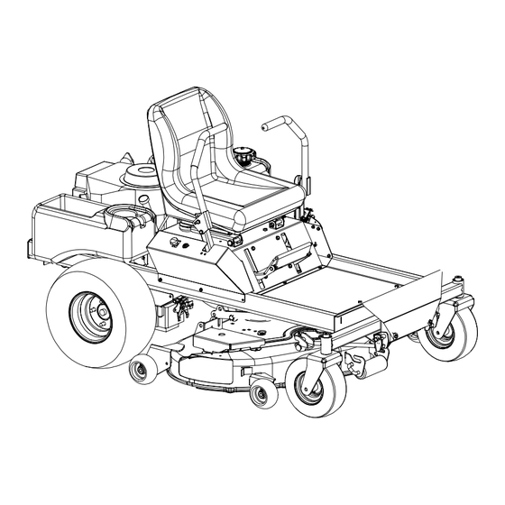
Page 9: Operating Instructions
OPERATING INSTRUCTIONS Figure. 1 Figure. 2 Choke Engine throttle/Choke Electric Blade Tach and (briggs only) (Kawasaki) Clutch Switch Hour Meter Engine throttle (briggs) Optional Ignition Switch A. General ing and raise the cutting deck to the trans- port position. Always allow other vehicles 1. -
Page 10: Controls
c. Avoid turning when going downhill, traction B. Controls is at a minimum going downhill. 1. Engine Ignition and Start Switch: (See Fig- d. Do not operate with discharge side of the ure 1.) Located on the instrument housing mower toward streets, buildings, play- below the right side of the operator’s seat. - Page 11 Steering Levers Brake Figure. 4 Fuel Shutoff Valve Figure. 3 Deck Lift Handle 8. Seat Adjustment Lever: The Seat Adjust- 4. Electric Blade Clutch Switch: (See Figure ment Lever is located beneath the seat. The 1.) Located on the right side of the mower Seat Adjustment Lever is used to move the beside the ignition switch.
-
Page 12: Initial Adjustments
C. Initial Adjustments switch, remove connection of the spark plugs and using the transport lever, lower 1. Check the fluid levels and tires: the mowing deck into the cutting position. Note: b. Using a ruler, pencil and paper, measure These checks should be made daily, and note the distance from the paved sur- before starting the engine. -
Page 13: Zero Turn Break-In And Operating Procedures
step “b.” above to make sure that the 2. That there are no spilled or leaking fuel desired cutting height and pitch and level or oil sources, nor loose fuel or hydraulic have been attained. If the dimensions are tank caps, hoses or fittings. not correct, repeat steps “c.”... - Page 14 right control panel). This must be (this is a safety check, the normal proce- increased to full speed (3525-3675 rpm) dure is for the operator to slowly bring after becoming familiar with the machine. the lap bars to the neutral position). 2.
-
Page 15: Maintenance And Service
g. Turn the ignition key in a clockwise direc- to be careful to avoid turning too fast and tion to the “Start” position until the engine too far. starts. After you have mastered operating the mower, use the transport lever to lower the Note: Do not hold the key in the “Start”... - Page 16 Linch Pins Figure. 6 “J” Pin e. Remove two linchpins (See Fig. 6) from c. Sharpen blades evenly at the original 30° the front of the mower. Pull the two (2) angle to maintain balanced cutting blades. spring-loaded “J” pins on the left and right Do not sharpen the underside of the rear side of the cutter deck.
-
Page 17: Hydrostatic Drive System
Hydrostatic Transaxles Figure. 8 Figure. 7 Spindle C.Electrical Circuit Note: When replacing belts do not over- Danger: tighten. Adjust the idler pulley so that a ten- pound pull with a spring scale between two Read General Safety Precautions Nos. 9 and 10. pulleys deflects the belt about 1/2". - Page 18 c. Store the battery with a full charge. A dis- switch must be off, the parking brake must be charged battery will freeze (refer to the engaged, and both steering levers must be table below). opened-out to the side in the neutral position. Once the engine is started, the seat must be occupied and the parking brake must be Specific Gravity...
-
Page 19: Tires
ing brake switch must be repositioned or stop when you dismount from the opera- perhaps replaced. If the engine does not tor’s seat, the seat switch must be start, engage the parking brake and start replaced. the engine. Swing one steering lever up to e. -
Page 20: Brakes
level, paved area. If the leaking tire is on a E. Brakes traction wheel, put blocks on each side of the While the mower is in motion, all braking is performed opposite traction wheel and jack up the tire dynamically through the hydraulic pumps and traction that leaks about an inch off the ground. -
Page 21: G.storage
Start the engine and allow it to run out owner-repairable. If a pump fails, contact your of fuel. This will prevent gum and varnish Cub Cadet dealer. Do not disassemble the deposits from forming. Replace the fuel fil- pump/motors. -
Page 22: Lubrication Chart
c. lubricate the wear points. Follow the Lubri- Clean the engine cooling fins and external cation Chart. surfaces.* d. After the first five hours, change the engine Lubricate wear points. Follow the Oil Chart. oil and engine oil filter. Lubricate all grease fittings. Follow the Lubrication Chart. -
Page 23: Performance Adjustments
Performance Adjustments B. Engine RPM Check and Adjustment Table 1 Description High RPM Spec. Low RPM Spec. A. High Speed Tracking Adjustment 15 Hp Kawasaki 3600 +/-50 1550 +/-100 If mower tracks to one side with both lap bars in fully 18 Hp Briggs &... -
Page 24: Deck Corner Ball Wheel Roller Settings
g. Verify proper throttle adjustment by check- b. Remove the bolts and lap bar and reposi- ing RPM readings as outlined above. tion to the second set of holes in the mount- ing block. C. Deck Corner Ball Wheel Roller Settings c. - Page 25 Check the right and left rear Drive tire pressure. Adjust as necessary to 8-10 psi. Front Measure blade-to-ground height at the front tip of Unit Left Side Point C of the right blade. To obtain an accurate mea- sure, align blades in parallel with mower center- line, (i.e.
-
Page 26: Wiring Diagram
WIRING DIAGRAM... -
Page 27: Slope Gauge
USE THIS PAGE AS A GUIDE TO DETERMINE SLOPES WHERE YOU MAY NOT OPERATE SAFELY. SIGHT AND HOLD THIS LEVEL WITH A VERTICAL TREE A POWER POLE A CORNER OF A BUILDING OR A FENCE POST 15° WARNING Do not mow on inclines with a slope in excess of 15 degrees (a rise of approximately 2-1/2 feet every 10 feet). A riding mower could overturn and cause serious injury. -
Page 28: Warranty
There is no other express warranty. How to obtain service Contact your authorized Cub Cadet servicing dealer who sold you your Cub Cadet equipment. If this dealer is not available, see the Consumer Yellow Pages under “lawn mowers” for the name of a dealer near you.
Need help?
Do you have a question about the 15HP Z-Force 44 53AA5D2L100 and is the answer not in the manual?
Questions and answers