Gigabyte GA-MA770-UD3 User Manual

Gigabyte GA-MA770-UD3 User Manual

Am2+/am2 socket motherboard for amd phenom fx processor/amd phenom x4 processor/amd phenom x3 processor/amd athlon x2 processor/amd athlon processor/amd sempron x2 processor/amd sempron processor
Table of Contents

Advertisement

GA-MA770-UD3/
GA-MA770-US3
AM2+/AM2 socket motherboard for
AMD Phenom
FX processor/AMD Phenom
X4 processor/
TM
TM
AMD Phenom
X3 processor/AMD Athlon
X2 processor/
TM
TM
AMD Athlon
processor/AMD Sempron
X2 processor/
TM
TM
AMD Sempron
processor
TM
User's Manual
Rev. 1001
12ME-MA77UDS3-1001R

Advertisement

Table of Contents
loading

Summary of Contents for Gigabyte GA-MA770-UD3

  • Page 1 GA-MA770-UD3/ GA-MA770-US3 AM2+/AM2 socket motherboard for AMD Phenom FX processor/AMD Phenom X4 processor/ AMD Phenom X3 processor/AMD Athlon X2 processor/ AMD Athlon processor/AMD Sempron X2 processor/ AMD Sempron processor User's Manual Rev. 1001 12ME-MA77UDS3-1001R...
  • Page 3: Identifying Your Motherboard Revision

    GIGABYTE's prior written permission. Documentation Classifications In order to assist in the use of this product, GIGABYTE provides the following types of documentations:  For quick set-up of the product, read the Quick Installation Guide included with the product.
  • Page 4: Table Of Contents

    Table of Contents Box Contents ......................... 6 Optional Items......................... 6 
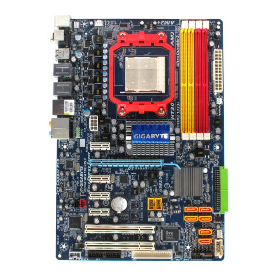
GA-MA770-UD3/US3 Motherboard Layout..............7 Block Diagram........................ 8 Chapter 1 Hardware Installation ..................9 Installation Precautions ..................9 Product Specifications ..................10 Installing the CPU and CPU Cooler .............. 13 1-3-1 Installing the CPU ....................
  • Page 5 Chapter 3 Drivers Installation ..................57 Installing Chipset Drivers ................57 Application Software..................58 Technical Manuals ..................58 Contact ......................59 System ......................59 Download Center.................... 60 Chapter 4 Unique Features ..................61 Xpress Recovery2 ..................61 BIOS Update Utilities ..................66 4-2-1 Updating the BIOS with the Q-Flash Utility ............
  • Page 6: Box Contents

    Box Contents GA-MA770-UD3 or GA-MA770-US3 motherboard Motherboard driver disk User's Manual Quick Installation Guide One IDE cable and one floppy disk drive cable Two SATA 3Gb/s cables I/O Shield • The box contents above are for reference only and the actual items shall depend on product package you obtain.
  • Page 7: Ga-Ma770-Ud3/Us3 Motherboard Layout

    RTL8111C PCIE_2 AMD SB700 PCIE_3 CODEC Main F_USB1 BIOS SATAII3 F_USB2 PCIE_4 SPDIF_OUT SATAII1 Backup SATAII0 BIOS SATAII2 TSB43AB23 PCI1 CLR_CMOS SATAII5 IT8720 PCI2 SATAII4 SYS_FAN1 F1_1394 COMA F_PANEL PWR_LED "*" The GA-MA770-UD3 adopt All-Solid Capacitor design. - 7 -...
  • Page 8: Block Diagram

    Block Diagram PCIe CLK CPU CLK+/-(200 MHz) (100 MHz) AMD Socket AM2+/AM2 DDR2 1200/1066/800/667 MHz 1 PCI Express x16 Dual Channel Memory Hyper Transport 3.0 PCI Express x16 AMD 770 PCI Express Bus ATA-133/100/66/33 PCIe CLK IDE Channel (100 MHz) 4 PCI Express x1 6 SATA 3Gb/s AMD SB700...
  • Page 9: Chapter 1 Hardware Installation

    Chapter 1 Hardware Installation Installation Precautions The motherboard contains numerous delicate electronic circuits and components which can become damaged as a result of electrostatic discharge (ESD). Prior to installation, carefully read the user's manual and follow these procedures: Prior to installation, do not remove or break motherboard S/N (Serial Number) sticker or •...
  • Page 10: Product Specifications

    X3 processor/AMD Athlon X2 processor/ AMD Athlon processor/AMD Sempron X2 processor/ AMD Sempron processor (Go to GIGABYTE's website for the latest CPU support list.) Hyper Transport Bus  5200/2000 MT/s Chipset North Bridge: AMD 770  South Bridge: AMD SB700 ...
  • Page 11 Internal Connectors 1 x 24-pin ATX main power connector  1 x 4-pin ATX 12V power connector  1 x floppy disk drive connector  1 x IDE connector  6 x SATA 3Gb/s connectors  1 x CPU fan header ...
  • Page 12 (Note 5) Available functions in EasyTune may differ by motherboard model. (Note 6) Due to the hardware limitation, you must install the AMD AM2+ Phenom Series CPU to enable support for Easy Energy Saver. GA-MA770-UD3/US3 Motherboard - 1 2 -...
  • Page 13: Installing The Cpu And Cpu Cooler

    Read the following guidelines before you begin to install the CPU: • Make sure that the motherboard supports the CPU. (Go to GIGABYTE's website for the latest CPU support list.) • Always turn off the computer and unplug the power cord from the power outlet before installing the CPU to prevent hardware damage.
  • Page 14 CPU, lowering the locking lever and latch- ing it into the fully locked position. Do not force the CPU into the CPU socket. The CPU cannot fit in if oriented incorrectly. Adjust the CPU orientation if this occurs. GA-MA770-UD3/US3 Motherboard - 1 4 -...
  • Page 15: Installing The Cpu Cooler

    1-3-2 Installing the CPU Cooler Follow the steps below to correctly install the CPU cooler on the CPU. (The following procedure uses the GIGABYTE cooler as the example.) Step 1: Step 2: Apply an even and thin layer of thermal grease Place the CPU cooler on the CPU.
  • Page 16: Installing The Memory

    • Make sure that the motherboard supports the memory. It is recommended that memory of the same capacity, brand, speed, and chips be used. (Go to GIGABYTE's website for the latest memory support list.) • Always turn off the computer and unplug the power cord from the power outlet before installing the memory to prevent hardware damage.
  • Page 17: Installing A Memory

    1-4-2 Installing a Memory Before installing a memory module , make sure to turn off the computer and unplug the power cord from the power outlet to prevent damage to the memory module. DDR2 DIMMs are not compatible to DDR DIMMs. Be sure to install DDR2 DIMMs on this motherboard.
  • Page 18: Installing An Expansion Card

    Make sure the card is securely seated in the slot and does not rock. • Removing the Card: Gently push back on the lever on the slot and then lift the card straight out from the slot. GA-MA770-UD3/US3 Motherboard - 1 8 -...
  • Page 19: Back Panel Connectors

    Back Panel Connectors PS/2 Keyboard and PS/2 Mouse Port Use the upper port (green) to connect a PS/2 mouse and the lower port (purple) to connect a PS/2 keyboard. Optical S/PDIF Out Connector This connector provides digital audio out to an external audio system that supports digital optical audio.
  • Page 20 Only microphones still MUST be connected to the default Mic in jack ( ). Refer to the instructions on setting up a 2/4/5.1/ 7.1-channel audio configuration in Chapter 5, "Configuring 2/4/5.1/7.1-Channel Audio." GA-MA770-UD3/US3 Motherboard - 2 0 -...
  • Page 21: Internal Connectors

    Internal Connectors ATX_12V F_AUDIO CD_IN CPU_FAN SPDIF_IN SYS_FAN1/SYS_FAN2 SPDIF_OUT PWR_FAN F_USB1/F_USB2 NB_FAN F1_1394 COMA SATAII0/1/2/3/4/5 PWR_LED F_PANEL CLR_CMOS Read the following guidelines before connecting external devices: • First make sure your devices are compliant with the connectors you wish to connect. •...
  • Page 22 Definition 3.3V 3.3V 3.3V -12V PS_ON(soft On/Off) Power Good 5V SB(stand by +5V) +12V +5V (Only for 2x12-pin ATX) +12V (Only for 2x12-pin ATX) 3.3V (Only for 2x12-pin ATX) GND (Only for 2x12-pin ATX) GA-MA770-UD3/US3 Motherboard - 2 2 -...
  • Page 23 3/4/5) CPU_FAN/SYS_FAN1/SYS_FAN2/PWR_FAN (Fan Headers) The motherboard has a 4-pin CPU fan header (CPU_FAN), a 3-pin (SYS_FAN2) and a 4-pin (SYS_FAN1) system fan headers, and a 3-pin power fan header (PWR_FAN). Most fan headers possess a foolproof insertion design. When connecting a fan cable, be sure to connect it in the correct orientation (the black connector wire is the ground wire).
  • Page 24 IDE devices (for example, master or slave). (For information about configuring master/slave settings for the IDE devices, read the instructions from the device manufacturers.) GA-MA770-UD3/US3 Motherboard - 2 4 -...
  • Page 25 9) SATAII0/1/2/3/4/5 (SATA 3Gb/s Connectors) The SATA connectors conform to SA TA 3Gb/s standard and are compatible with SA TA 1.5Gb/s standard. Each SA TA connector supports a single SA TA device. The AMD SB700 controller supports RAID 0, RAID 1 and RAID 10. Refer to Chapter 5, "Configuring SA TA Hard Drive(s)," for instructions on configuring a RAID array.
  • Page 26: F_Panel

    LED, hard drive activity LED, speaker and etc. When connecting your chassis front panel module to this header, make sure the wire assign- ments and the pin assignments are matched correctly. GA-MA770-UD3/US3 Motherboard - 2 6 -...
  • Page 27: Front Panel Audio Header

    12) F_AUDIO (Front Panel Audio Header) The front panel audio header supports Intel High Definition audio (HD) and AC'97 audio. You may connect your chassis front panel audio module to this header. Make sure the wire assignments of the module connector match the pin assignments of the motherboard header. Incorrect connection between the module connector and the motherboard header will make the device unable to work or even damage it.
  • Page 28 HDMI display to the graphics card and have digital audio output from the HDMI display at the same time. For information about connecting the S/PDIF digital audio cable, carefully read the manual for your expansion card. Pin No. Definition SPDIFO GA-MA770-UD3/US3 Motherboard - 2 8 -...
  • Page 29: Usb/Ieee 1394A Headers

    16) F_USB1/F_USB2 (USB Headers, Yellow) The headers conform to USB 2.0/1.1 specification. Each USB header can provide two USB ports via an optional USB bracket. For purchasing the optional USB bracket, please contact the local dealer. Pin No. Definition Power (5V) Power (5V) USB DX- USB DY-...
  • Page 30 The COM header can provide one serial port via an optional COM port cable. For purchasing the optional COM port cable, please contact the local dealer. Pin No. Definition NDCD- NSIN NSOUT NDTR- NDSR- NRTS- NCTS- NRI- No Pin GA-MA770-UD3/US3 Motherboard - 3 0 -...
  • Page 31 20) BAT (BATTERY) The battery provides power to keep the values (such as BIOS configurations, date, and time information) in the CMOS when the computer is turned off. Replace the battery when the battery voltage drops to a low level, or the CMOS values may not be accurate or may be lost. You may clear the CMOS values by removing the battery: 1.
  • Page 32: Clearing Cmos Jumper

    Failure to do so may cause damage to the motherboard. • After system restart, go to BIOS Setup to load factory defaults (select Load Optimized Defaults) or manually configure the BIOS settings (refer to Chapter 2, "BIOS Setup," for BIOS configurations). GA-MA770-UD3/US3 Motherboard - 3 2 -...
  • Page 33: Chapter 2 Bios Setup

    To see more advanced BIOS Setup menu options, you can press <Ctrl> + <F1> in the main menu of the BIOS Setup program. To upgrade the BIOS, use either the GIGABYTE Q-Flash or @BIOS utility . Q-Flash allows the user to quickly and easily upgrade or back up BIOS without entering the •...
  • Page 34: Startup Screen

    Function Keys B. The POST Screen Award Modular BIOS v6.00PG, An Energy Star Ally Copyright (C) 1984-2008, Award Software, Inc. AMD 770 BIOS for GA-MA770-UD3 E1 Motherboard Model BIOS Version Function Keys <DEL>: BIOS Setup <F9>: XpressRecovery2 <F12>: Boot Menu <End>: Qflash...
  • Page 35: The Main Menu

    Once you enter the BIOS Setup program, the Main Menu (as shown below) appears on the screen. Use arrow keys to move among the items and press <Enter> to accept or enter a sub-menu. (Sample BIOS Version: GA-MA770-UD3 E1) CMOS Setup Utility-Copyright (C) 1984-2008 Award Software ...
  • Page 36      Exit Without Saving Abandon all changes and the previous settings remain in effect. Pressing <Y> to the confirmation message will exit BIOS Setup. (Pressing <Esc> can also carry out this task.) GA-MA770-UD3/US3 Motherboard - 3 6 -...
  • Page 37: Mb Intelligent Tweaker(M.i.t.)

    MB Intelligent Tweaker(M.I.T.) CMOS Setup Utility-Copyright (C) 1984-2008 Award Software MB Intelligent Tweaker(M.I.T.) CPU Clock Ratio [Auto] Item Help (Note) CPU NorthBridge Freq. [Auto] Menu Level CPU Host Clock Control [Auto] x CPU Frequency (MHz) PCIE Clock (MHz) [Auto] HT Link Frequency [Auto] Set Memory Clock [Auto]...
  • Page 38: Memory Clock

    Enter: Select +/-/PU/PD: Value F10: Save ESC: Exit F1: General Help F5: Previous Values F6: Fail-Safe Defaults F7: Optimized Defaults (Note) This item is present only if you install a CPU that supports this feature. GA-MA770-UD3/US3 Motherboard - 3 8 -...
  • Page 39 CMOS Setup Utility-Copyright (C) 1984-2008 Award Software DRAM Configuration x Row Cycle Time Auto Item Help Menu Level x RAS to RAS Delay Auto : Move Enter: Select +/-/PU/PD: Value F10: Save ESC: Exit F1: General Help F5: Previous Values F6: Fail-Safe Defaults F7: Optimized Defaults CPU Host Clock Control, CPU Frequency (MHz), Set Memory Clock, Memory Clock...
  • Page 40 Supplies the South Bridge voltage as required. (Default) +0.025V ~ +0.375V Increases South Bridge voltage by 0.025V to 0.375V at 0.025V increment. (Note) This item is present only if you install a CPU that supports this feature. GA-MA770-UD3/US3 Motherboard - 4 0 -...
  • Page 41: Standard Cmos Features

    Standard CMOS Features CMOS Setup Utility-Copyright (C) 1984-2008 Award Software Standard CMOS Features Date (mm:dd:yy) Thu, Nov 6 2008 Item Help Time (hh:mm:ss) 18:25:04 Menu Level  IDE Channel 0 Master [None]  IDE Channel 0 Slave [None]  IDE Channel 1 Master [None] ...
  • Page 42 These fields are read-only and are determined by the BIOS POST. Base Memory Also called conventional memory. Typically, 640 KB will be reserved for the MS-DOS operating system. Extended Memory The amount of extended memory. GA-MA770-UD3/US3 Motherboard - 4 2 -...
  • Page 43: Advanced Bios Features

    Advanced BIOS Features CMOS Setup Utility-Copyright (C) 1984-2008 Award Software Advanced BIOS Features Virtualization [Disabled] Item Help (Note) Patch AMD TLB Erratum [Enabled] Menu Level AMD K8 Cool&Quiet control [Auto]  Hard Disk Boot Priority [Press Enter] First Boot Device [Floppy] Second Boot Device [Hard Disk]...
  • Page 44 (Default: Disabled) Full Screen LOGO Show Allows you to determine whether to display the GIGABYTE Logo at system startup. Disabled displays normal POST message. (Default: Enabled) Init Display First Specifies the first initiation of the monitor display from the installed PCI graphics card or PCI Express graphics card.
  • Page 45: Integrated Peripherals

    Integrated Peripherals CMOS Setup Utility-Copyright (C) 1984-2008 Award Software Integrated Peripherals OnChip IDE Channel [Enabled] Item Help Onboard 1394 Function [Enabled] Menu Level Onboard LAN Function [Enabled] Onboard LAN Boot ROM [Disabled]  SMART LAN [Press Enter] OnChip SATA Controller [Enabled] OnChip SATA Type [Native IDE]...
  • Page 46 Note: Part 4-5 and Part 7-8 are not used in a 10/100 Mbps environment, so their Status fields will show Open, and the length shown is the approximate length of the attached LAN cable. GA-MA770-UD3/US3 Motherboard - 4 6 -...
  • Page 47: Onboard Audio Function

    OnChip SATA Controller Enables or disables the integrated SATA controller. (Default: Enabled) OnChip SATA Type (SATAII0~SATAII3 connectors) Configures the operating mode of the integrated SA TA controller. Native IDE Allows the SATA controller to operate in Native IDE mode. (Default) Enable Native IDE mode if you wish to install operating systems that support Native mode, e.g.
  • Page 48 ECP Mode Use DMA Selects DMA channel for the LPT port in ECP mode. This item is configurable only if Parallel Port Mode is set to ECP or ECP+EPP mode. Options are: 3 (default), 1. GA-MA770-UD3/US3 Motherboard - 4 8 -...
  • Page 49: Power Management Setup

    Power Management Setup CMOS Setup Utility-Copyright (C) 1984-2008 Award Software Power Management Setup ACPI Suspend Type [S3(STR)] Item Help Soft-Off by Power button [Instant-off] Menu Level USB Wake Up from S3 [Enabled] Modem Ring Resume [Disabled] PME Event Wake Up [Enabled] (Note) HPET Support...
  • Page 50 Note: When using this function, avoid inadequate shutdown from the operating system or removal of the AC power, or the settings may not be effective. (Note) Supported on Windows Vista operating system only. ® ® GA-MA770-UD3/US3 Motherboard - 5 0 -...
  • Page 51: Pnp/Pci Configurations

    PnP/PCI Configurations CMOS Setup Utility-Copyright (C) 1984-2008 Award Software PnP/PCI Configurations PCI IRQ Assignment [Auto] Item Help PCI IRQ Assignment [Auto] Menu Level : Move Enter: Select +/-/PU/PD: Value F10: Save ESC: Exit F1: General Help F5: Previous Values F6: Fail-Safe Defaults F7: Optimized Defaults PCI1 IRQ Assignment Auto...
  • Page 52: Pc Health Status

    CI header. If the system chassis cover is removed, this field will show "Y es", otherwise it will show "No". To clear the chassis intrusion status record, set Reset Case Open Status to Enabled, save the settings to CMOS, and then restart your system. GA-MA770-UD3/US3 Motherboard - 5 2 -...
  • Page 53 Current Voltage(V) Vcore/DDR2 1.8V/+3.3V/+12V Displays the current system voltages. Current System/CPU Temperature Displays current system/CPU temperature. Current CPU/SYSTEM/POWER FAN Speed (RPM) Displays current CPU/system/power fan speed. CPU Warning Temperature Sets the warning threshold for CPU temperature. When CPU temperature exceeds the threshold, BIOS will emit warning sound.
  • Page 54: Load Fail-Safe Defaults

    Press <Enter> on this item and then press the <Y> key to load the optimal BIOS default settings. The BIOS defaults settings helps the system to operate in optimum state. Always load the Optimized defaults after updating the BIOS or after clearing the CMOS values. GA-MA770-UD3/US3 Motherboard - 5 4 -...
  • Page 55: Set Supervisor/User Password

    2-12 Set Supervisor/User Password CMOS Setup Utility-Copyright (C) 1984-2008 Award Software  MB Intelligent Tweaker(M.I.T.) Load Fail-Safe Defaults  Standard CMOS Features Load Optimized Defaults  Advanced BIOS Features Set Supervisor Password  Integrated Peripherals Set User Password  Power Management Setup Save &...
  • Page 56: Save & Exit Setup

    Press <Enter> on this item and press the <Y> key. This exits the BIOS Setup without saving the changes made in BIOS Setup to the CMOS. Press <N> or <Esc> to return to the BIOS Setup Main Menu. GA-MA770-UD3/US3 Motherboard - 5 6 -...
  • Page 57: Chapter 3 Drivers Installation

    Chapter 3 Drivers Installation • Before installing the drivers, first install the operating system. (The following instructions use Windows XP as the example operating system.) • After installing the operating system, insert the motherboard driver disk into your opti cal drive. The driver Autorun screen is automatically displayed which looks like that shown in the screen shot below.
  • Page 58: Application Software

    Application Software This page displays all the utilities and applications that GIGABYTE develops and some free software. You can click the Install button on the right of an item to install it. Technical Manuals This page provides GIGABYTE's application guides, content descriptions for this driver disk, and the motherboard manuals.
  • Page 59: Contact

    Contact Click the URL on this page to link to the GIGABYTE Web site. Or read the last page of th is manual to check the contact information for GIGABYTE Taiwan headquarter or worldwide branch of fices. System This page provides the basic system information.
  • Page 60: Download Center

    Download Center To update the BIOS, drivers, or applications, click the Download Center button to link to the GIGABYTE Web site. The latest version of the BIOS, drivers, or applications will be displayed. GA-MA770-UD3/US3 Motherboard - 6 0 -...
  • Page 61: Chapter 4 Unique Features

    Chapter 4 Unique Features Xpress Recovery2 Xpress Recovery2 is a utility that allows you to quickly compress and back up your system data and perform restoration of it. Supporting NTFS, FAT32, and FAT16 file systems, Xpress Recovery2 can back up data on PATA and SATA hard drives and restore it. Before You Begin: •...
  • Page 62: Installation And Configuration

    Recovery2 (10 GB or more is recommended; actual size requirements vary, depending on the amount of data) (Figure 2). Figure 2 Figure 1 3. Select a file system (for example, NTFS) and begin the installation of the operating system (Figure 3). Figure 3 GA-MA770-UD3/US3 Motherboard - 6 2 -...
  • Page 63 4. After the operating system is installed, right-click the My Computer icon on your desktop and select Manage (Figure 4). Go to Computer Management to check disk allocation. Xpress Recovery2 will save the backup file to the unallocated space (black stripe along the top)(Figure 5). Please note that if there is no enough unallocated space, Xpress Recovery2 cannot save the backup file.
  • Page 64 If you wish to enter Xpress Recovery2 later, simply press <F9> during the POST (Figure 9). Award Modular BIOS v6.00PG, An Energy Star Ally Copyright (C) 1984-2008, Award Software, Inc. AMD 770 BIOS for GA-MA770-UD3 E1 <DEL>: BIOS Setup <F9>: XpressRecovery2 <F12>: Boot Menu <End>: Qflash 11/06/2008-RD780-SB700-6A66AG09C-00 Figure 9 C.
  • Page 65 D. Using the Restore Function in Xpress Recovery2 Select RESTORE to restore the backup to your hard drive in case the system breaks down. The RESTORE option will not be present if no backup is created before (Figure 13, 14). Figure 13 Figure 14 E.
  • Page 66: Bios Update Utilities

    4-2-1 Updating the BIOS with the Q-Flash Utility A. Before You Begin: 1. From GIGABYTE's website, download the latest compressed BIOS update file that matches your motherboard model. 2. Extract the file and save the new BIOS file (e.g. MA770UD3.F1) to your floppy disk, USB flash drive, or hard drive.
  • Page 67 B. Updating the BIOS When updating the BIOS, choose the location where the BIOS file is saved. The follow procedure assumes that you save the BIOS file to a floppy disk. Step 1: 1. Insert the floppy disk containing the BIOS file into the floppy disk drive. In the main menu of Q- Flash, use the up or down arrow key to select Update BIOS from Drive and press <Enter>.
  • Page 68 Press <Y> to load BIOS defaults Step 6: Select Save & Exit Setup and then press <Y> to save settings to CMOS and exit BIOS Setup. The procedure is complete after the system restarts. GA-MA770-UD3/US3 Motherboard - 6 8 -...
  • Page 69: Updating The Bios With The @Bios Utility

    BIOS or a system that is unable to start. 3. Do not use the G.O.M. (GIGABYTE Online Management) function when using @BIOS. 4. GIGABYTE product warranty does not cover any BIOS damage or system failure resulting from an inadequate BIOS flashing.
  • Page 70: Easytune 6

    EasyTune 6 GIGABYTE's EasyTune 6 is a simple and easy-to-use interface that allows users to fine-tune their system settings or do overclock/overvoltage in Windows environment. The user-friendly EasyTune 6 interface also includes tabbed pages for CPU and memory information, lettings users read their system- related information without the need to install additional software.
  • Page 71: Easy Energy Saver

    The Easy Energy Saver Interface A. Meter Mode In Meter Mode, GIGABYTE Easy Energy Saver shows how much power they have saved in a set period of time. Meter Mode - Button Information Table Button Description...
  • Page 72 Energy Saver is under the enable status, and power savings meter is unable to reset to zero. (Note 5) Easy Energy Saver Meter will automatically reset when the total power saving reaches 99999999 Watts. GA-MA770-UD3/US3 Motherboard - 7 2 -...
  • Page 73: Chapter 5 Appendix

    Chapter 5 Appendix Configuring SATA Hard Drive(s) To configure SATA hard drive(s), follow the steps below: A. Install SATA hard drive(s) in your computer . B. Configure SATA controller mode in BIOS Setup. C . Configure a RAID array in RAID BIOS. (Note 1) D.
  • Page 74 The BIOS Setup menus described in this section may differ from the exact settings for your motherboard. The actual BIOS Setup menu options you will see shall depend on the motherboard you have and the BIOS version. GA-MA770-UD3/US3 Motherboard - 74 -...
  • Page 75 C. Configuring RAID set in RAID BIOS Enter the RAID BIOS setup utility to configure a RAID array. Skip this step if you do not want to create RAID. Step 1: After the POST memory test begins and before the operating system boot begins, look for a message which says "Press <Ctrl-F>...
  • Page 76 Cache Mode: WriteThru Drives Assignments Channel:ID Drive Model Capacity (MB) Assignment 1:Mas WDC WD800JD-22LSA0 80026 2:Mas WDC WD800JD-22LSA0 80026 Keys Available [] Up [] Down [ESC] Exit [Space] Change [Ctrl-Y] Save [PgUp/Dn] Page Change Figure 5 GA-MA770-UD3/US3 Motherboard - 76 -...
  • Page 77 In the following procedure, we'll create RAID 0 as an example. 1. Under the RAID Mode section, press the <SP ACE> key to select RAID 0. 2. Set the Stripe Block size. 64 KB is the default. 3. Under the Drives Assignments section, press the up or down arrow key to highlight a drive. 4.
  • Page 78 Cache Mode: WriteThru Drives Assignments Channel:ID Drive Model Capacity (MB) 1:Mas WDC WD800JD-22LSA0 80026 2:Mas WDC WD800JD-22LSA0 80026 Press Ctrl-Y to delete the data in the disk! or press any other key to abort... Figure 9 GA-MA770-UD3/US3 Motherboard - 78 -...
  • Page 79: Making A Sata Raid/Ahci Driver Diskette For Windows Xp

    5-1-2 Making a SATA RAID/AHCI Driver Diskette for Windows XP (Required for AHCI and RAID Mode) To successfully install operating system onto SA TA hard drive(s) that is/are configured to RAID/AHCI mode, you need to install the SA TA controller driver during the OS installation. Without the driver , the hard drive may not be recognized during the Windows setup process.
  • Page 80: Installing The Sata Raid/Ahci Driver And Operating System

    * If you do not have any device support disks from a mass storage device manufacturer, or do not want to specify additional mass storage devices for use with Windows, press ENTER. S=Specify Additional Device ENTER=Continue F3=Exit Figure 2 GA-MA770-UD3/US3 Motherboard - 80 -...
  • Page 81 Step 3: When Setup correctly recognizes the AMD SB700 SATA RAID/AHCI driver in the floppy disk, a controller menu similar to Figure 3 below will appear . Use the arrow keys to select ATI AHCI Compatible RAID Controller-x86 platform and press <Enter>. Windows Setup You have chosen to configure a SCSI Adapter for use with Windows, using a device support disk provided by an adapter manufacturer.
  • Page 82 Windows (R) XP to run on your computer. To set up Windows XP now, press ENTER. To repair a Windows XP installation using Recovery Console, press R. To quit Setup without installing Windows XP, press F3. Enter= Continue R=Repair F3=Exit Figure 5 GA-MA770-UD3/US3 Motherboard - 82 -...
  • Page 83 B. Installing Windows Vista (The procedure below assumes that only one RAID array exists in your system.) Step 1: Restart your system to boot from the Windows Vista setup disk and perform standard OS installation steps. When a screen similar to that below appears (RAID hard drive will not be detected at this stage), select Load Driver.
  • Page 84 After the driver is loaded, the RAID drive will appear. Select the RAID drive and then press Next to continue the OS installation (Figure 9). Figure 9 The install menus described in this chapter are for reference only and may differ by driver version. GA-MA770-UD3/US3 Motherboard - 84 -...
  • Page 85: Configuring Audio Input And Output

    Configuring Audio Input and Output 5-2-1 Configuring 2/4/5.1/7.1-Channel Audio The motherboard provides six audio jacks on the back panel which support 2/4/5.1/7.1-channel audio. The picture to the right shows the default audio jack Center/Subwoofer Line In assignments. Speaker Out The integrated HD (High Definition) audio provides Front Speaker Out Rear Speaker Out jack retasking capability that allows the user to change...
  • Page 86 D. Muting the Back Panel Audio (For HD Audio Only): Click the tool icon on the Audio I/O tab. On the Connector Settings box, select the Mute rear panel output when front headphone plugged in check box. Click OK to complete. GA-MA770-UD3/US3 Motherboard - 86 -...
  • Page 87: Installing The S/Pdif In Cable (Optional)

    5-2-2 Installing the S/PDIF In Cable (Optional) The S/PDIF in cable provides S/PDIF in functionality. Coaxial Optical S/PDIF In S/PDIF In S/PDIF In: The S/PDIF in jacks allow you to input digital audio signals to the computer for audio processing. A.
  • Page 88: Configuring Microphone Recording

    Note: The microphone functions on the front panel and back panel cannot be used at the same time. Step 3: Locate the Volume icon in your system tray and click it to open the volume control panel. GA-MA770-UD3/US3 Motherboard - 88 -...
  • Page 89 Step 4: To hear the sound being recorded during the record- ing process when using the microphone function on the front panel, do not select the Mute check box under Front Pink In or Front Green In in Master Volume. It is recommended that you set the volume at a middle level.
  • Page 90: Using The Sound Recorder

    3. To play a sound file, click the Play button 4. To stop playing, click the Stop button 5. You may use the Fast Forward button move to the beginning of a file or the Fast Back- ward button to the end. GA-MA770-UD3/US3 Motherboard - 90 -...
  • Page 91: Troubleshooting

    5-3-1 Frequently Asked Questions To read more F AQs for your motherboard, please go to the Support\Motherboard\F AQ page on GIGABYTE's website. Q: In the BIOS Setup program, why are some BIOS options missing? A: Some advanced options are hidden in the BIOS Setup program. Press <Delete> to enter BIOS Setup during the POST.
  • Page 92: Troubleshooting Procedure

    Turn on the power to start the computer. Press <Delete> to enter BIOS Setup. Select "Load Fail-Safe Defaults" (or "Load Optimized Defaults"). Select "Save & Exit Setup" to save changes and exit BIOS Setup. (Continued...) GA-MA770-UD3/US3 Motherboard - 92 -...
  • Page 93 The power supply, When the computer is turned on, is the CPU cooler running? CPU or CPU socket might fail. The problem is verified and solved. The graphics card, Check if there is display on your monitor. expansion slot, or monitor might fail.
  • Page 94: Regulatory Statements

    "end of life" product. Restriction of Hazardous Substances (RoHS) Directive Statement GIGABYTE products have not intended to add and safe from hazardous substances (Cd, Pb, Hg, Cr+6, PBDE and PBB). The parts and components have been carefully selected to meet RoHS requirement.
  • Page 95 Finally, we suggest that you practice other environmentally friendly actions by understanding and using the energy-saving features of this product (where applicable), recycling the inner and outer packaging (including shipping containers) this product was delivered in, and by disposing of or recycling used batteries properly.
  • Page 96 GA-MA770-UD3/US3 Motherboard - 96 -...
  • Page 97 - 97 - Appendix...
  • Page 98 GA-MA770-UD3/US3 Motherboard - 98 -...
  • Page 99 TEL: +86-24-83992901 FAX: +86-24-83992909 GIGA-BYTE SINGAPORE PTE. LTD. - Singapore      WEB address : http://www.gigabyte.sg GIGABYTE TECHNOLOGY (INDIA) LIMITED - India      WEB address : http://www.gigabyte.in Thailand     ...
  • Page 100 WEB address : http://www.giga-byte.kz Czech Republic      You may go to the GIGABYTE website, select your language WEB address : http://www.gigabyte.cz in the language list on the top right corner of the website.      GIGABYTE Global Service System...

This manual is also suitable for:

Ga-ma770-us3

Table of Contents