Epson TM-T88II Series User Manual
Pos printer
Hide thumbs
Also See for TM-T88II Series:
- Operator's manual (50 pages) ,
- Manual (10 pages) ,
- User manual (4 pages)
Table of Contents
Advertisement
Advertisement
Table of Contents

Related Manuals for Epson TM-T88II Series


Summary of Contents for Epson TM-T88II Series
- Page 1 TM-T88II Series User’s Manual 400852003...
-
Page 2: Caution Labels
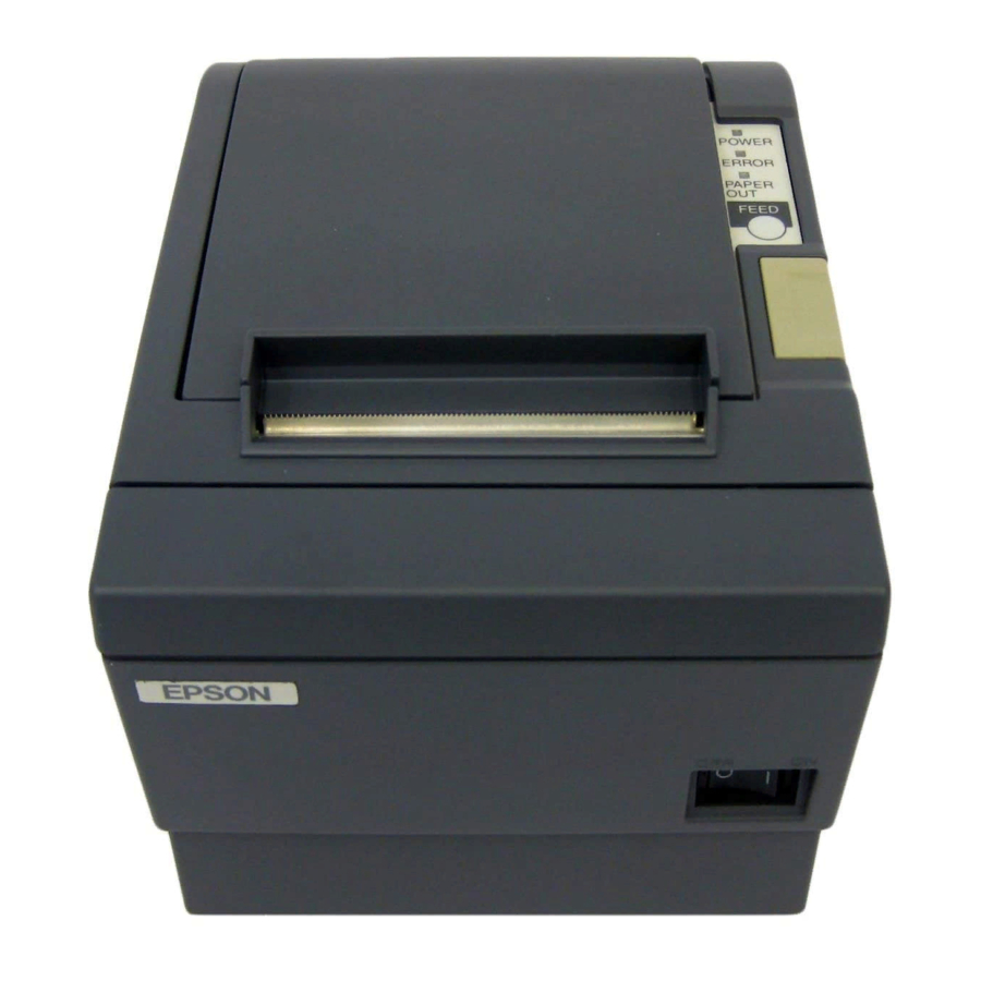
Printer Parts and Labels Cutter cover Caution Labels CAUTION: Thermal head is hot. ATTENTION: La téte thermique est chaude. VORSICHT: Der Thermalkopf ist heiß. Caution label above for the drawer kick-out connector. Printer cover Control panel POWER ERROR PAPER FEED... -
Page 3: Quick Reference
Manual. For a complete listing of topics, see the Contents. Printer Parts and Labels Ordering Paper Where to order paper. Setting Up the Printer How to set up the printer. Installing and Replacing Paper How to load or change the paper roll. Solving Problems How to correct problems. - Page 4 Seiko Epson Corporation. No patent liability is assumed with respect to the use of the information contained herein. While every precaution has been taken in the preparation of this book, Seiko Epson Corporation assumes no responsibility for errors or omissions.
-
Page 5: Emc And Safety Standards Applied
EMC and Safety Standards Applied Product Name: TM-T88II Model Name: M129B The following standards are applied only to the printers that are so labeled. (EMC is tested using the EPSON PS-170 power supply) Europe: North America: Japan: Oceania: Taiwan: The connection of a non-shielded printer interface cable to this printer will invalidate the EMC standards of this device. -
Page 6: Fcc Compliance Statement
CE Marking The printer conforms to the following Directives and Norms Directive 89/336/EEC Directive 90/384/EEC FCC Compliance Statement For American Users This equipment has been tested and found to comply with the limits for a Class A digital device, pursuant to Part 15 of the FCC Rules. These limits are designed to provide reasonable protection against harmful interference when the equipment is operated in a commercial environment. - Page 7 GEREÄUSCHPEGEL Gemäß der Dritten Verordnung zum Gerätesicherheitsgesetz (Maschinenlärminformations- Verordnung-3. GSGV) ist der arbeitsplatzbezogene Geräusch-Emissionswert kleiner als 70 dB(A) (basierend auf ISO 7779).
-
Page 8: About This Manual
About This Manual Setting Up and Using Chapter 1 contains information on unpacking the printer and setting it up. Chapter 2 contains information on using the printer. Chapter 3 contains troubleshooting information. Reference Chapter 4 contains specifications. Appendix A tells how to change the DIP switch and paper near end settings. -
Page 9: Application Software
Introduction Features TM-T88II Series printers are high-quality POS printers that can print on a paper roll. The printers have the following features: Printing High-speed printing: 28.4 lines/second (4.23mm (1/6”) feed) maximum. Low-noise thermal printing. High reliability due to a stable mechanism. -
Page 10: Options And Accessories
Options and Accessories EPSON power supply unit, PS-170. Affixing tapes (model: DF-10). RS-485 interface board can be installed as a dealer option. Wall hanging bracket set (WH-10). viii Introduction... -
Page 11: Ordering Paper And Supplies
Ordering Paper and Supplies You can order thermal roll paper from the supplier in your area. Specified Thermal Roll Paper: NTP080-80 In Japan: In U.S.A.: In Europe: In Southeast Asia: Nakagawa Seisakujo 2-5-21 Nishiki-Cho Warabi-Shi Saitama-Ken 335 Japan Tel: (048) 444-8211 Fax: (048) 443-6652 Nakagawa Mfg (USA) Inc. - Page 12 Other Qualified Suppliers for Thermal Paper The following suppliers sell thermal paper that may be used if desired. Contact each company for information. Original paper: Original paper: Original paper: Original paper: x Introduction TF50KS-E Nippon Paper Industry Co., Ltd. 1-12-1, Yuraku-Cho, Chiyoda-Ku Tokyo 100 Japan Tel: 03-3218-8000 Fax: 03-3216-1375...
-
Page 13: Table Of Contents
Unpacking ............1-1 Connecting the Cables and Grounding the Printer ......1-2 Connecting the Drawer . - Page 14 Appendix A DIP Switch and Paper Near End Settings Setting the DIP Switches ..........A-1 DIP switch functions .
-
Page 15: Chapter 1 Setting Up The Printer
The illustration below shows the items included for the standard specification printer. Printer Hexagonal lock screws (only for the serial interface) See the note on page 1-3 for information about the hexagonal lock screws. Paper roll Switch cover Setting Up the Printer 1-1... -
Page 16: Connecting The Cables And Grounding The Printer
Connecting the Cables and Grounding the Printer You can connect up to four cables to the printer. They all connect to the connector panel on the back of the printer, which is shown below: Interface (The shape of the interface... -
Page 17: Connecting The Drawer
2. If the printer has a serial interface, tighten the screws on both sides of the cable connector. Note: Your printer has inch-type hexagonal lock screws installed. If your interface cable requires millimeter-type screws, replace the inch-type screws with the enclosed millimeter-type screws using a hex screwdriver (5 mm). - Page 18 Plug the drawer cable into the drawer kick-out connector on the back of the printer next to the power supply connector. Anschließen der Schublade WARNUNG: Eine für den Drucker geeignete Schublade verwenden. Bei Verwendung einer falschen Schublade kann diese oder der Drucker beschädigt werden.
-
Page 19: Grounding The Printer
2. Connect the ground wire to the printer using one of the FG screws on the back of the printer, as shown. Connecting the Power Supply Use the optional EPSON PS-170 or equivalent power supply for your printer. anschlie ß... - Page 20 WARNING: Make sure you use the EPSON PS-170 power supply or equivalent. Using an incorrect power supply may cause fire or electrical shock. CAUTION: When connecting or disconnecting the power supply from the printer, make sure the power supply is not plugged into an electrical outlet.
-
Page 21: Installing Or Replacing The Paper Roll
1. Make sure the printer is not receiving data; otherwise, data may be lost. 2. Open the paper roll cover by pressing the cover-open button. If the cover-open button will not open the cover, see page 3-4 or 3-6 in Troubleshooting. - Page 22 4. Insert the paper roll as shown. 5. Be sure to note the correct direction that the paper comes off the roll. 1-8 Setting Up the Printer...
- Page 23 6. Pull out a small amount of paper, as shown. Then close the cover. 7. Tear off the paper as shown. Setting Up the Printer 1-9...
-
Page 24: Using The Power Switch Cover
If you want to use this cover, install it as shown in the illustration below. Self Test The self test lets you know if your printer is operating properly. It checks the control circuits, printer mechanisms, print quality, ROM version, and DIP switch settings. - Page 25 2. While holding down the FEED button, turn on the printer using the switch on the front of the printer to begin the self test. The self test prints the printer settings and then prints the following, cuts the paper, and pauses. (The PAPER OUT light blinks.)
-
Page 26: Adjustments And Settings
Adjustments and Settings TM-T88II Series printers are set up at the factory to be appropriate for almost all users. There are, however, some settings for users with special requirements. Your printer has DIP switches that allow you to change communication settings, such as handshaking and parity check, as well as print density. -
Page 27: Chapter 2 Using The Printer
Chapter 2 Using the Printer Operating the Control Panel You can control the basic paper feeding operations of the printer with the button on the control panel. The indicator lights help you monitor the printer’s status. Control Panel Button The button can be disabled by the ESC c 5 command. - Page 28 Panel lights POWER The POWER light is on whenever the printer is on. ERROR This indicates an error. See Chapter 3 for information on what to do when this light comes on. PAPER OUT This light indicates the near end of the paper roll. Install a new paper roll, and the printer will continue printing.
-
Page 29: Chapter 3 Troubleshooting
Press the printer cover until the cover audibly clicks into place. The ERROR light is blinking and the printer does not print. First, turn off the printer and check for a paper jam. (See the paper jam description on page 3-3.) Troubleshooting 3-1... - Page 30 If there is no paper jam and the printer has been printing for quite a while, the print head may be overheated. If the print head is overheated, the printer will resume printing when the head has cooled (usually within two or three minutes).
-
Page 31: Cleaning The Print Head
2. Clean the thermal element of the print head with a cotton swab moistened with an alcohol solvent (ethanol, methanol, or IPA). Paper handling problems Paper is jammed inside the printer. CAUTION: Do not touch the print head because it can be very hot after printing continuously for a long time. - Page 32 To clear a paper jam, follow the steps below: 1. Turn the printer off and press the cover open button to open the cover. 2. Remove the jammed paper, put the roll back in the printer, and close the cover.
-
Page 33: Auto Cutter Problems
The auto cutter is jammed. If a foreign object, such as a push pin or paper clip, drops in the auto cutter and causes the auto cutter to lock up, the printer enters an error state and begins the recovery operation automatically. - Page 34 If the auto cutter does not return to its normal position by itself, follow the steps below to correct the problem: 1. Pull the cutter cover toward you so that you can rotate the cutter motor knob. 2. Following the instructions on the label, rotate the knob until the appears in the hole.
-
Page 35: Hexadecimal Dump
During the hex dump all commands except DLE EOT and DLE ENQ are disabled. 5. Open the cover to set the printer off line, so that it will print the last line. 6. Close the cover and turn off the printer or reset it to turn off the hex dump mode. - Page 36 3-8 Troubleshooting...
-
Page 37: Chapter 4 Reference Information
28.4 lines/second maximum (4.23 mm (1/6”) feed, at 24 V, 28° C (82° F), density level 2) Speed is adjusted depending on the applied voltage to the printer and head temperature conditions automatically. Approximately 16.5 lines/second (4.23 mm feed (1/6”)) Approximately 70 mm/second (approximately 2.76”/second) - Page 38 Printing speed — when a ladder bar code is printed: Notes: Printing speed may be slower, depending on the data transmission speed and the combination of control commands. There may be variations in printing after switching the mode of the printing speed.
-
Page 39: Paper Specifications
Standard W x H in mm (") Font A 1.41 x 3.39 12 x 24 (0.06” x .13”) Font B 0.99 x 2.40 9 x 17 (0.04” x .09”) Kanji 3.39 x 3.39 24 x 24 (0.13’’x.13’’) * CPL = Characters Per Line * Space between characters is not included * Characters can be scaled up to 64 times as large as the standard sizes. -
Page 40: Electrical Characteristics
Supply voltage: Current consumption: (at 24V) Note: Maximum 1A for drawer kick-out driving 4-4 Reference Information +24 VDC ± 7% (optional power supply: EPSON PS-170) High-speed Mean: Approximately 1.7A mode: (character font A -N all columns printing) Peak: Approximately 7.7A Low-power- Mean: Approximately 1.2A... -
Page 41: Reliability
Reliability Life: MTBF: MCBF: Environmental Conditions Temperature: Humidity: Mechanism: 15,000,000 lines Thermal head: 100 million pulses, 100 km Auto cutter: 1,500,000 cuts (End of Life is defined to have reached the end of its life when it reaches the beginning of the Wearout Period.) 360,000 hours (Failure is defined as Random Failure occurring at the time of the Random... - Page 42 4-6 Reference Information...
-
Page 43: Appendix A Dip Switch And Paper Near End Settings
DIP switch or paper near end settings. Setting the DIP Switches DIP switch functions Your printer has two sets of DIP switches. The functions of the switches are shown in the following tables. Serial interface specifications Set 1... - Page 44 Transmission Speed Transmission Speed (BPS)-bits per second 2400 4800 9600 19200 Set 2 Function Handshaking (BUSY condition) Reserved: do not change settings Selects print density Reserved: do not change settings Reserved: do not change settings I/F pin 6 reset signal I/F pin 25 reset signal A-2 DIP Switch and Paper Near End Settings Off line or...
- Page 45 • If you turn on DIP switch 2-7 or 2-8 while the printer is turned on, the printer may be reset, depending on the signal state. DIP switches should not be changed while the printer power is on.
-
Page 46: Parallel Interface Specifications
Parallel interface specifications Set 1 Function Auto line feed Receive buffer capacity 1-3~ Undefined Set 2 Function Handshaking (BUSY condition) Reserved (Do not change settings) Selects print density 2-5~ Reserved (Do not change settings) I/F pin 31 reset signal (Do not change settings) Print Density Selection Print Density 1 Low power consumption mode... - Page 47 • If you turn on DIP switch 2-8 while the printer is turned on, the printer may be reset, depending on the signal state. Do not change DIP switches while the printer power is on.
-
Page 48: Changing The Dip Switch Settings
If you need to change settings, follow the steps below to make your changes: CAUTION: Turn off the printer before removing the DIP switch cover to prevent an electric short, which can damage the printer. 1. Make sure the printer is turned off. -
Page 49: Adjusting The Paper Near End Detector
If you use a paper roll with a core with an outside diameter of more than 18 mm, it is better to change to the upper setting, as described below. 1. Open the printer cover, and remove the paper roll. 2. Loosen the adjusting screw and move the tab up to the upper setting. - Page 50 A-8 DIP Switch and Paper Near End Settings...
- Page 52 Printed in Japan 1999.12...