Table of Contents
Advertisement
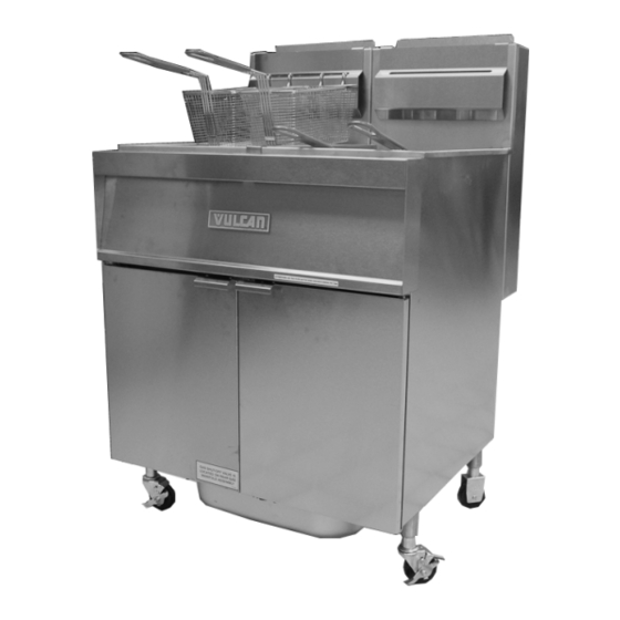
2GR45AF KLEENSCREEN
FRYER BATTERY
This Manual is prepared for the use of trained Vulcan Service
Technicians and should not be used by those not properly qualified.
This manual is not intended to be all encompassing. If you have not
attended a Vulcan Service School for this product, you should read,
in its entirety, the repair procedure you wish to perform to
determine if you have the necessary tools, instruments and skills
required to perform the procedure. Procedures for which you do not
have the necessary tools, instruments and skills should be
performed by a trained Vulcan Service Technician.
The reproduction, transfer, sale or other use of this Manual, without
the express written consent of Vulcan, is prohibited.
This manual has been provided to you by ITW Food Equipment
Group LLC ("ITW FEG") without charge and remains the property
of ITW FEG, and by accepting this manual you agree that you will
return it to ITW FEG promptly upon its request for such return at
any time in the future.
For additional information on Vulcan-Hart Company or to locate an authorized parts
and service provider in your area, visit our website at www.vulcanhart.com.
A product of VULCAN-HART
SERVICE MANUAL
GRA SERIES GAS FRYERS WITH
KLEENSCREEN PLUS®
FILTRATION SYSTEMS
MODEL
ML
1GR45A
136647
1GR65A
136648
1GR85A
136649
2GR45AF
136650
2GR65AF
136651
2GR85AF
136652
3GR45AF
136653
3GR65AF
136654
MODEL
ML
3GR85AF
136655
4GR45AF
136656
4GR65AF
136657
4GR85AF
136681
2XGR45AF
136658
2XGR65AF
136659
2XGR85AF
136660
LOUISVILLE, KY 40201-0696
F25377 (March 2010)
Advertisement
Table of Contents

Related Manuals for Vulcan-Hart 1GR45A


Summary of Contents for Vulcan-Hart 1GR45A
- Page 1 ITW FEG promptly upon its request for such return at any time in the future. For additional information on Vulcan-Hart Company or to locate an authorized parts and service provider in your area, visit our website at www.vulcanhart.com.
-
Page 2: Table Of Contents
Kleenscreen Filtering System ............. 36 © VULCAN 2010... -
Page 3: General
GRA SERIES GAS FRYERS - GENERAL GENERAL INTRODUCTION SINGLE FLOOR MODEL FRYERS This Service Manual covers specific service Fryers with the Filter-Ready option installed, use the information related to the models listed on the front Mobile Filter. For service information related to the cover. -
Page 4: Kleenscreen Filtration System
GRA SERIES GAS FRYERS - GENERAL KLEENSCREEN FILTRATION TOOLS SYSTEM Standard The Kleenscreen filtration system is integrated into • Standard set of hand tools. the GRA Series fryer battery. The filter is housed in a • VOM with A/C current tester (any quality VOM pull-out drawer assembly at the base of the fryer. -
Page 5: Removal And Replacement Of Parts
GRA SERIES GAS FRYERS - REMOVAL AND REPLACEMENT OF PARTS REMOVAL AND REPLACEMENT OF PARTS SPLASH GUARD (KLEENSCREEN FRYERS ONLY) Open fryer section doors. Remove screws securing splash guard. Remove screws securing controls. Remove cooking controls. Disconnect lead wires from the component being replaced then remove from control box. -
Page 6: Gas Burners
GRA SERIES GAS FRYERS - REMOVAL AND REPLACEMENT OF PARTS Pull filter drawer out, remove filter tank Remove cooking controls to access burner(s) if assembly and push the tank support arms back necessary. into place under the fryer. Remove splash guard from base frame. Remove drain pipe to access burner(s) if From underneath the fryer: necessary. -
Page 7: Gas Orifice
GRA SERIES GAS FRYERS - REMOVAL AND REPLACEMENT OF PARTS Reverse procedure to install and check for proper operation. GAS COMBINATION VALVE Remove burner. Reverse procedure to install and check for proper operation. GAS ORIFICE NOTE: If a gas combination valve is malfunctioning, do not attempt to disassemble the valve for repair. -
Page 8: Gas Pilot
GRA SERIES GAS FRYERS - REMOVAL AND REPLACEMENT OF PARTS Disconnect pilot tube from gas combination valve. Disconnect gas line fittings then remove gas combination valve. Remove gas line fittings from gas combination valve and install (in same orientation) on the replacement valve. Reverse procedure to install and check for proper operation. -
Page 9: Temperature Probe
GRA SERIES GAS FRYERS - REMOVAL AND REPLACEMENT OF PARTS and probe to the fryer heat tube (inside tank) TEMPERATURE PROBE then remove probe. Do not sharply bend and kink, or clamp down on the capillary tube or damage may occur. Drain shortening from fryer tank. -
Page 10: Power Supply Box Components
GRA SERIES GAS FRYERS - REMOVAL AND REPLACEMENT OF PARTS POWER SUPPLY BOX COMPONENTS Remove screws securing the high limit to mounting bracket. Remove the capillary tube retaining and packing nuts. NOTE: The power supply box must be removed to access the following components: Ignition control module, transformer, R1 pump motor relay, R2 fill relay. -
Page 11: Fill Solenoid Valve (Kleenscreen Fryers Only)
GRA SERIES GAS FRYERS - REMOVAL AND REPLACEMENT OF PARTS Disconnect swivel pipe fitting at rear of fry tank. Reverse procedure to install and check for proper operation. FILL SOLENOID VALVE (KLEENSCREEN FRYERS ONLY) REAR VIEW SHOWN Disconnect fill solenoid valve lead wire connector (4 pin) from power supply box. -
Page 12: Fry Tank Assembly
GRA SERIES GAS FRYERS - REMOVAL AND REPLACEMENT OF PARTS Open the fryer section doors above the filter FRY TANK ASSEMBLY tank drawer. Pull filter drawer out, remove filter tank assembly and push the tank support arms back into place under the fryer. Remove splash guard from base frame. - Page 13 GRA SERIES GAS FRYERS - REMOVAL AND REPLACEMENT OF PARTS Remove POWER SUPPLY BOX. Disconnect swivel fitting from fry tank at the rear On battery fryer sections only, remove splash (shortening line inlet to fry tank). guard from base frame. 10.
-
Page 14: Service Procedures And Adjustments
GRA SERIES GAS FRYERS - SERVICE PROCEDURES AND ADJUSTMENTS SERVICE PROCEDURES AND ADJUSTMENTS TEMPERATURE PROBE TEST The temperature probe is an RTD (resistance temperature detector) of the thermistor type. As temperature increases the resistance value decreases. Probe Fault If a temperature probe fault occurs, red diagnostic LED on back of control assembly (inside control box cover) will flash. -
Page 15: Cooking Control Calibration
GRA SERIES GAS FRYERS - SERVICE PROCEDURES AND ADJUSTMENTS COOKING CONTROL CALIBRATION NOTE: Verify condition of temperature probe as outlined under TEMPERATURE PROBE TEST before proceeding. Check the level of shortening in fry tank. The level must be between the MIN & MAX fill lines before proceeding. -
Page 16: Flame Sense Current Check
GRA SERIES GAS FRYERS - SERVICE PROCEDURES AND ADJUSTMENTS control calls for heat, the heat output is activated and the main valve coil on the combination valve is then energized, allowing gas flow to the burners. Terminal Description MV (main voltage) - 24VAC output will be present, providing the ignitor/flame sense electrode is sensing an adequate pilot fame. - Page 17 GRA SERIES GAS FRYERS - SERVICE PROCEDURES AND ADJUSTMENTS Turn the power switch on and verify the ignition control module is receiving power from the transformer. If 24VAC is present, then module is receiving power. Turn the power switch off and continue with procedure.
-
Page 18: Gas Manifold Pressure Adjustment
GRA SERIES GAS FRYERS - SERVICE PROCEDURES AND ADJUSTMENTS adequate sizing. GAS MANIFOLD PRESSURE If adjustment is necessary, continue with ADJUSTMENT procedure. Open the door(s) and remove drain pipe. Remove burners as necessary. Remove the adjustment screw cap to access the pressure adjustment screw on gas combination valve. -
Page 19: Electrical Operation
GRA SERIES GAS FRYERS - ELECTRICAL OPERATION ELECTRICAL OPERATION COMPONENT FUNCTION FRYER CONTROLS Cooking Control ....Monitors and evaluates input signals to the control: Activates heat output signal to maintain shortening temperature;... - Page 20 GRA SERIES GAS FRYERS - ELECTRICAL OPERATION KLEENSCREEN FILTER CONTROLS Fill Solenoid Valve ... . When energized by filter switch, the solenoid valve opens to allow the flow of shortening thru filtering system. Pump Motor .
-
Page 21: Power Supply Box Components
GRA SERIES GAS FRYERS - ELECTRICAL OPERATION POWER SUPPLY BOX COMPONENTS Page 21 of 36 F25377 (March 2010) -
Page 22: Sequence Of Operation
GRA SERIES GAS FRYERS - ELECTRICAL OPERATION SEQUENCE OF OPERATION Refer to schematic diagram AI 2727 for Cooking Control operation. NOTE: Make sure melt select switch reflects type of shortening being used (solid/liquid). Conditions. Fryer connected to correct supply voltage and properly grounded. Gas supply is on and gas combination valve is open. -
Page 23: Kleenscreen Filtering System
GRA SERIES GAS FRYERS - ELECTRICAL OPERATION Kleenscreen Filtering System Refer to schematic diagram AI 2728 for Kleenscreen Filter System operation. Refer to Installation & Operation manual and Kleenscreen Filtration System Supplement manual for specific instructions on filtering. NOTE: The discard valve handle is connected to a mechanical valve and magnetic reed switch assembly to route the flow of shortening in the filtering system and supply power to the pump motor. -
Page 24: Schematic Diagrams
GRA SERIES GAS FRYERS - ELECTRICAL OPERATION SCHEMATIC DIAGRAMS Fryers Without KleenScreen Filtration System F25377 (March 2010) Page 24 of 36... -
Page 25: Fryers With Kleenscreen Filtration System
GRA SERIES GAS FRYERS - ELECTRICAL OPERATION Fryers With KleenScreen Filtration System Page 25 of 36 F25377 (March 2010) -
Page 26: Wiring Diagrams
GRA SERIES GAS FRYERS - ELECTRICAL OPERATION WIRING DIAGRAMS Fryers Without KleenScreen Filtration System F25377 (March 2010) Page 26 of 36... - Page 27 GRA SERIES GAS FRYERS - ELECTRICAL OPERATION Page 27 of 36 F25377 (March 2010)
- Page 28 GRA SERIES GAS FRYERS - ELECTRICAL OPERATION Fryers With KleenScreen Filtration System F25377 (March 2010) Page 28 of 36...
- Page 29 GRA SERIES GAS FRYERS - ELECTRICAL OPERATION Page 29 of 36 F25377 (March 2010)
-
Page 30: Frymate (Dump Station)
GRA SERIES GAS FRYERS - ELECTRICAL OPERATION Frymate (Dump Station) F25377 (March 2010) Page 30 of 36... -
Page 31: Troubleshooting
GRA SERIES GAS FRYERS - TROUBLESHOOTING TROUBLESHOOTING ALL MODELS SYMPTOMS POSSIBLE CAUSES No spark to ignite pilot gas. Drain valve switch open or switch malfunction. Shorted electrode or an improper ground on ignitor/flame sense. Ignitor cable open. Interconnecting wiring malfunction. Ignition Module malfunction. -
Page 32: Ignition Module
GRA SERIES GAS FRYERS - TROUBLESHOOTING IGNITION MODULE The ignition module has two LED's; one for flame sensing and one for ignition system status. • Flame LED (Yellow) - Indicates pilot burner flame presence and signal strength. • Status LED (Green) - Indicates ignition system operation status and error conditions. LED Flash Code Descriptions - Flame LED (yellow) or Status LED (green): •... - Page 33 GRA SERIES GAS FRYERS - TROUBLESHOOTING IGNITION SYSTEM STATUS LED CODES (GREEN) - PART NO. 857207-1 SINGLE TRY LOCKOUT IGNITION MODULE LED Flash Indicates System Action Possible Causes Code No Call for Heat None None Fast Flash Startup Flame sense calibration None automatically occurs immediately - Pilot flame sense...
- Page 34 GRA SERIES GAS FRYERS - TROUBLESHOOTING IGNITION SYSTEM STATUS LED CODES (GREEN) - PART NO. 857207-1 SINGLE TRY LOCKOUT IGNITION MODULE LED Flash Indicates System Action Possible Causes Code Low voltage to ignition Module will not proceed to trial for 1.
-
Page 35: Frymate (Dump Station) With Optional Heater
GRA SERIES GAS FRYERS - TROUBLESHOOTING FRYMATE (DUMP STATION) WITH OPTIONAL HEATER SYMPTOM POSSIBLE CAUSES No heat. 1. Unplugged. 2. Power switch off or inoperative. 3. Main circuit breaker off or open. 4. Malfunctioning heater assembly. Page 35 of 36 F25377 (March 2010) -
Page 36: Kleenscreen Filtering System
GRA SERIES GAS FRYERS - TROUBLESHOOTING KLEENSCREEN FILTERING SYSTEM SYMPTOM POSSIBLE CAUSES Shortening not filtering, pump motor is 1. Filter screen plugged. energized. 2. Clog in filter system lines. NOTE: If using solid shortening, when all filtered shortening is returned to the fry tank and filter power switch is off, open the filter drawer approximately one inch.
Need help?
Do you have a question about the 1GR45A and is the answer not in the manual?
Questions and answers