Table of Contents
Advertisement
L
IGHT
P
ACKAGED
Prior to installation, thoroughly familiarize yourself with this Installation Manual. Observe all safety warnings.
It is your responsibility to install the product safely and to educate the customer on its safe use.
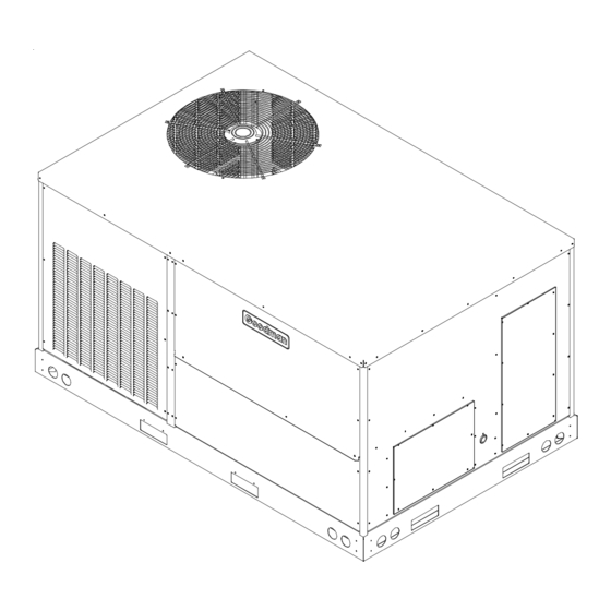
These installation instructions cover the outdoor
installation of single package electric heating and
cooling units. See the Specification Sheet applicable
to your model* for information regarding accessories.
IO-399A
5/12
I
NSTALLATION
C
OMMERCIAL
H
3 T
- 6 T
ON
RECOGNIZE THIS SYMBOL AS A SAFETY PRECAUTION.
ATTENTION INSTALLING PERSONNEL
During installation or repair, caution is to be observed.
All information contained herein is subject to change without notice.
Goodman Manufacturing Company, L.P.
5151 Felipe, Suite 500, Houston, TX 77056
www.goodmanmfg.com
© 2010,2012 Goodman Manufacturing Company, L.P.
I
NSTRUCTIONS
S
ELF
& C
EATING
CPC/CPH S
ON
*NOTE:
www.amana-hac.com
F
OR
-C
ONTAINED
U
OOLING
NIT
ERIES
Please contact your distributor or
our website for the applicable
Specification Sheet referred to in
this manual.
Advertisement
Table of Contents

Related Manuals for Goodman CPC SERIES

Summary of Contents for Goodman CPC SERIES
- Page 1 NSTALLATION NSTRUCTIONS IGHT OMMERCIAL ONTAINED & C ACKAGED EATING OOLING - 6 T CPC/CPH S ERIES RECOGNIZE THIS SYMBOL AS A SAFETY PRECAUTION. ATTENTION INSTALLING PERSONNEL Prior to installation, thoroughly familiarize yourself with this Installation Manual. Observe all safety warnings. During installation or repair, caution is to be observed.
-
Page 2: Table Of Contents
Index REPLACEMENT PARTS Replacement Parts ............2 RDERING ARTS Safety Instructions ............2 When reporting shortages or damages, or ordering repair parts, give the complete unit model and serial numbers General Information ............3 as stamped on the unit’s nameplate. Unit Location .............. -
Page 3: General Information
ATIONAL ODES WARNING This product is designed and manufactured to permit instal- lation in accordance with National Codes. It is the installer’s “ ” HIS UNIT MUST NOT BE USED AS A CONSTRUCTION HEATER responsibility to install the product in accordance with Na- DURING THE FINISHING PHASES OF CONSTRUCTION ON A NEW tional Codes and/or prevailing local codes and regulations. -
Page 4: Unit Location
• Allow minimum clearances from the enclosure for fire NOTE: When inspecting the unit for transportation damage, protection, proper operation, and service access (see remove all packaging materials. Recycle or dispose of the Unit Clearances). These clearances must be packaging material according to local codes. permanently maintained. -
Page 5: Clearances
Full perimeter roof curbs are available from the factory and Adequate clearance around the unit should be kept for safety, are shipped unassembled. Field assembly, squaring, level- service, maintenance, and proper unit operation. A total clear- ing and mounting on the roof structure are the responsibility ance of 75”... -
Page 6: Roof Top Duct Connections
RIGGING DETAILS ROTRUSION Inspect curb to ensure that none of the utility services (elec- WARNING tric) routed through the curb protrude above the curb. O PREVENT PROPERTY DAMAGE, THE UNIT SHOULD REMAIN IN AN UPRIGHT POSITION DURING ALL RIGGING AND MOVING OPERATIONS. O FACILITATE CAUTION LIFTING AND MOVING WHEN A CRANE IS USED, PLACE THE UNIT IN AN... - Page 7 Lower unit carefully onto roof mounting curb. While rigging unit, center of gravity will cause condenser end to be lower than supply air end. To assist in determining rigging requirements, unit weights are shown as follows: RETURN CONDENSER COIL EVAPORATOR COIL SUPPLY COMPRESSOR CORNER &...
-
Page 8: Electrical Wiring
All line voltage connections must be made through weather- CAUTION proof fittings. All exterior power supply and ground wiring must be in approved weatherproof conduit. O PREVENT SEVERE DAMAGE TO THE BOTTOM OF THE UNIT DO NOT The main power supply wiring to the unit and low voltage FORK LIFT UNIT AFTER WOOD STRUTS HAVE BEEN REMOVED wiring to accessory controls must be done in accordance with Bring condenser end of unit into alignment with the curb. - Page 9 MAIN POWER LOW VOLTAGE BLOCK RETURN 3.5 DIA. POWER THRU THE CURB LOW VOLTAGE ENTRANCE 4 1/2” POWER THRU THE CURB CONTROL BOX 47 1/2” 7 1/2” WARNING ELECTRICAL ENTRANCE AND THRU CURB AILURE OF UNIT DUE TO OPERATION ON IMPROPER LINE VOLTAGE OLTAGE ONTROL IRING...
-
Page 10: Circulating Air And Filters
CIRCULATING AIR AND FILTERS STARTUP, ADJUSTMENTS, AND CHECKS UCTWORK WARNING The supply duct from the unit through a wall may be installed without clearance. However, minimum unit clearances must HIGH VOLTAGE! be maintained (see “Clearances” section). The supply duct O AVOID PERSONAL INJURY OR DEATH DUE TO should be provided with an access panel large enough to ELECTRICAL SHOCK OND THE FRAME OF THIS UNIT TO... - Page 11 System Voltage - That nominal voltage value assigned to a OOLS EQUIRED circuit or system for the purpose of designating its voltage Refrigeration gauge and manifold class. Voltmeter Nameplate Voltage - That voltage assigned to a piece of Clamp-on ammeter equipment for the purpose of designating its voltage class Ohmmeter and for the purpose of defining the minimum and maximum...
- Page 12 ing and clamps. The entire refrigeration system has been factory charged and tested, making it unnecessary to field charge. Factory charges are shown on the unit nameplate. Install service manifold hoses. Gauges should read satura- tion pressure corresponding to ambient temperature. Charge should be checked to obtain 12°...
-
Page 13: Heat Pump Operation
11. Slowly raise the heating temperature setting. When EFRIGERATION ERFORMANCE HECK the heating first stage makes contact, stop raising the Under normal summertime (full load) operating conditions, temperature setting.. The compressor, blower and fan superheat should be between 8°F and 12°F and sub-cooling should now be running with the reversing valve in the measured at the condenser outlet should be 15°F (nominal). -
Page 14: Air Flow Adjustments
EFROST ONTROL C O O LIN G S E RV IC E P O RT R E V E RS IN G V A LV E During operation the power to the circuit board is controlled S E RV IC E VA LV E by a temperature sensor, which is clamped to a feeder tube entering the outdoor coil. -
Page 15: Drive Adjustments
DRIVE ADJUSTMENTS CAUTION MOTOR SHEAVE ADJUSTMENTS HEET METAL PARTS SCREWS CLIPS AND SIMILAR ITEMS INHERENTLY , & 2 ARIABLE ITCH OTOR HEAVES HAVE SHARP EDGES AND IT IS NECESSARY THAT THE INSTALLER AND The driving and driven motor sheaves should be in align- SERVICE PERSONNEL EXERCISE CAUTION ment with each other and the shafts parallel. -
Page 16: Service
UBRICATION NDERCHARGE The fan shaft bearings, the 1 to 2 HP supply fan motors the An undercharged heat pump on the heating cycle will cause condenser fan motors and compressors are permanently lu- low discharge pressure resulting in low suction pressure and bricated. -
Page 17: Appendix A Blower Performance Tables
APPENDIX A BLOWER PERFORMANCE TABLES DIRECT DRIVE STANDARD DOWN SHOT AND HORIZONTAL CPC/H036 DIRECT DRIVE DOWN SHOT EXTERNAL STATIC STAN DARD SPEED TAP PRESSURE (ESP) AMPS WATTS in w.c. 0.10 1287 1.66 0.20 1233 1.63 0.30 1176 1.59 0.40 1107 1.55 0.50 1044... -
Page 18: Standard Down Shot And Horizontal (048)
APPENDIX A BLOWER PERFORMANCE TABLES DIRECT DRIVE STANDARD DOWN SHOT AND HORIZONTAL CPC/H048 DIRECT DRIVE DOWN SHOT EXTERNAL STATIC STAN DARD SPEED TAP PRESSURE (ESP) AMPS WATTS in w.c. 0.10 1602 2.48 0.20 1538 2.37 0.30 1474 2.26 0.40 1390 2.15 0.50 1306... -
Page 19: Standard Cpc/H060 Down Shot
APPENDIX A BLOWER PERFORMANCE TABLES DIRECT DRIVE STANDARD CPC/H060 DOWN SHOT CPC/H060 DIRECT DRIVE DOWN SHOT EXTERNAL STATIC SPEED STANDARD PRESSURE (ESP) AMPS WATTS C FM in w.c. 0.10 1334 1.65 0.20 1286 1.75 0.30 1212 1.83 0.40 1144 1.94 0.50 1077 1.99... -
Page 20: Standard Cpc/H060 Horizontal
APPENDIX A BLOWER PERFORMANCE TABLES DIRECT DRIVE STANDARD CPC/H060 HORIZONTAL CPC/H060 DIRECT DRIVE HORIZONTAL EXTERNAL STATIC SPEED STANDAR D PRESSURE (ESP) AMPS WATTS in w.c. 0.10 1355 1.57 0.20 1281 1.66 0.30 1235 1.76 0.40 1168 1.81 0.50 1118 1.94 0.60 1049 2.03... -
Page 21: Belt Drive
APPENDIX A BLOWER PERFORMANCE TABLES BELT DRIVE STANDARD DOWN SHOT CPC/H036 STANDARD BELT DRIVE DOWN SHOT TURNS OPEN ESP, In 1424 0.30 1239 0.23 1520 0.39 1292 0.29 1073 0.22 0.14 1439 0.40 1192 0.30 0.21 0.12 1350 0.42 1101 0.31 0.22 1028... -
Page 22: High Static Down Shot
APPENDIX A BLOWER PERFORMANCE TABLES BELT DRIVE HIGH STATIC DOWN SHOT CPC/H036 HIGH STATIC BELT DRIVE DOWN SHOT TURNS OPEN ESP, In 1692 0.54 1449 0.41 1173 0.29 1678 0.58 1397 0.44 1107 0.31 0.21 1681 0.65 1381 0.49 1078 0.34 0.22 1681... -
Page 23: Standard Horizontal
APPENDIX A BLOWER PERFORMANCE TABLES BELT DRIVE STANDARD HORIZONTAL CPC/H036 STANDARD BELT DRIVE HORIZONTAL TURNS OPEN ESP, In 1658 0.35 1489 0.28 1560 0.36 1339 0.28 1129 0.21 1682 0.47 1436 0.36 1196 0.27 0.19 1581 0.50 1354 0.38 1096 0.28 0.18 1266... -
Page 24: High Static Horizontal
APPENDIX A BLOWER PERFORMANCE TABLES BELT DRIVE HIGH STATIC HORIZONTAL CPC/H036 HIGH STATIC BELT DRIVE HORIZONTAL TURNS OPEN ESP, In 1742 0.50 1431 0.36 1626 0.52 1357 0.39 1078 0.27 1611 0.56 1315 0.42 1011 0.28 1605 0.62 1299 0.46 0.31 1605 0.68... -
Page 25: Appendix B Electrical Data
APPENDIX B ELECTRICAL DATA ELECTRICAL DATA OUTDOOR VOLTAGE COMPRESSOR INDOOR INDOOR FAN MOT OR VOLTAGE LIMITATION FAN MOTOR MODELS MOT OR (NAMEPLATE) APPLICATION MIN. MAX. 208/230-60-1 16.67 1.40 DD STD STATIC DD STD STATIC 208/230-60-3 10.45 73.0 1.40 3 TON BD STD STATIC 460-60-3 5.77... - Page 26 APPENDIX B ELECTRICAL DATA MINIMUM AIR FLOW FOR ELECTRIC HEAT HEATER KIT UNIT MINIMUM CFM MOD EL N UMBER EHK*-10 1250 3 TON EHK*-15 1250 EHK*-10 1300 4 TON EHK*-15 1400 EHK*-18 1400 EHK*-10 1700 5 TON EHK*-15 1700 EHK*-20 1800 EHK*-10 2100...
-
Page 27: Appendix C Unit Dimensions
APPENDIX C UNIT DIMENSIONS 47 1/2” 73 1/4” 38 13/16”* 74 1/16” *6 Ton - 42 13/16 48 3/16” 11” 4 7/8” 17” 7 3/8” RETURN 25” 19 7/16” 12” SUPPLY RETURN DRAIN THRU CURB EMBOSS LOCATION 5 7/8” THRU THE BASE 6 1/4”... - Page 28 Goodman Manufacturing Company, L.P. 5151 Felipe, Suite 500, Houston, TX 77056 www.goodmanmfg.com www.amana-hac.com © 2010,2012 Goodman Manufacturing Company, L.P.
Need help?
Do you have a question about the CPC SERIES and is the answer not in the manual?
Questions and answers