Weslo CROSSWALK 5.2T User Manual
831.21902.0
Hide thumbs
Also See for CROSSWALK 5.2T:
- User manual (28 pages) ,
- Manual del usuario (28 pages) ,
- User manual (28 pages)

Related Manuals for Weslo CROSSWALK 5.2T


Summary of Contents for Weslo CROSSWALK 5.2T
- Page 1 ® Model No. 831.21902.0 Serial No. Manual User's Write the serial number in the space above for reference. Serial Number Decal • Assembly • Operation • Maintenance • Part List and Drawing Sears, Roebuck and Co. Hoffman Estates, IL 60179...
-
Page 2: Table Of Contents
TABLE OF CONTENTS WARNING DECAL PLACEMENT ............... IMPORTANT PRECAUTIONS ..............BEFORE YOU BEGIN ................ PART IDENTIFICATION CHART ..............ASSEMBLY ................OPERATION AND ADJUSTMENT ............. HOW TO FOLD AND MOVE THE TREADMILL ........... TROUBLESHOOTING ..............EXERCISE GUIDELINES ..............PART LIST ................EXPLODED DRAWING .............. -
Page 3: Important Precautions
iMPORTANT PRECAUTIONS WARNING: To reduce the risk ofburns, fire, e ect.o s hock, orinjury t opersons, read all important precautions and instructions in this manual and all warnings on your treadmill before using your treadmill. Sears assumes no responsibility for personal injury or property damage sus- tained by or through the use of this product. - Page 4 20. The heart rate monitor is not a medical Never insert any object into any opening on the treadmill. device. Various factors, including the user's movement, may affect the accuracy of heart rate readings. The heart rate monitor inspect and properly tighten all parts of the intended only as an exercise aid in determin- treadmill regularly.
-
Page 5: Before You Begin
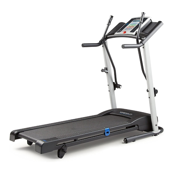
BEFORE YOU BEGIN Thank you for selecting the new WESLO _ reading this manual, please see the back cover of this CROSSWALK 5.2T treadmill. The CROSSWALK 5.2T manual. To help us assist you, note the product model treadmill offers a selection of features designed to number and serial number before contacting us. -
Page 6: Part Identification Chart
PART iDENTiFiCATiON CHART Use the drawings below to identify small parts used for assembly. The number in parentheses below each draw- ing is the key number of the part, from the PART LIST near the end of this manual. The number following the key number is the quantity used for assembly. -
Page 7: Assembly
Left parts are marked "L" or "Left" and right parts To watch an assembly I-_'lml![_l_bym_ • video, go to are marked "R" or "Right." assembly/kmart/weslo To identify small parts, see page 6. or use your mobile http ://productvideo.co/ Assembly requires the following tools: read the QR code at the phone or smartphone to r_u--='_"... - Page 8 With the help of a second person, carefully tip the treadmill onto its side. Unfold the Frame (51) away from the Uprights (53, 54). Orient the Base (52) as shown. Attach the Base to the Left Upright (53) and the Right Upright (54) with four M10 x 58mm Bolts (2) and four MIO Nuts (73).
-
Page 9: M5 X 16Mm Screw (85)
Set the Right Handrail (33) on the console assembly. Make sure that the console wire is Console Wire not pinched. Remove the tie from the bracket on the Right Handrail. If necessary, press the Cage Nut (102) back into place. Start an M5 x 16mm Screw (85) with an M5 Star Washer (7) into the Right Handrail, and then start two M4.2 x 19mm Screws (10) into... -
Page 10: M4.2 X 18Mm Screw (58)
Set the console assembly on the Uprights (53, 54). Make sure that no wires are pinched. Console Assembly Start four M8 x 15mm Bolts (8) with four M8 Star Washers (5) into the Uprights as shown. Do not tighten the Bolts yet. Start an M8 x 15mm Bolt (8) with an M8 Star Washer (5) into each Upright (53, 54). -
Page 11: X 3 1/2" Screw (103)
Attach the Left Upper Body Arm (105) to the Left Upright (53) with two 1/4" x 3 1/2" Screws (103), two 1/4" Flat Washers (101), and two M10 Star Washers (9). Make sure that the Left Upper Console Body Arm is on the side of the console assem- Assembl, bly shown. -
Page 12: Operation And Adjustment
OPERATION AND ADJUSTMENT HOW TO CONNECT THE POWER CORD nominal 120=volt circuit capable of carrying 15 or more amps. To avoid overloading the circuit, do Use a Surge Suppressor not plug other electrical devices, except for low= power devices such as cell phone chargers, into Your treadmill, like other electronic equipment, can be the surge suppressor or into an outlet on the same... - Page 13 CONSOLE DIAGRAM t.SB%,s_3P, ..WEIGHT LOSS PERFORMANCE SELECT START STOP A WARNING: reduce ious _str_o_ and_h_ K_ _ildro_aw_y _. ADVERTENClA: TARGET PULSE © entiond_ e E m_u_ldel U_oMante_g_a_os _o_do_ --Clip FEATURES OF THE CONSOLE To turn on the power, see page 14. To use the man= ual mode, see page 14.
- Page 14 HOW TO TURN ON THE POWER the manual mode by pressing the Workout Select button repeatedly until only zeros appear in the iMPORTANT: if the treadmill has been exposed to displays. cold temperatures, allow it to warm to room tem- perature before turning on the power, if you do not Start the walking...
- Page 15 The lower left ment is selected, hold down the Stop button, insert display--As you ex- the key into the console, and then release the Stop button. An M for metric kilometers or an E ercise, the lower left u._u_ DtSr. display can show the for English miles will appear in the priority display.
- Page 16 HOW TO USE A PRESET WORKOUT for the next segment, the speed setting will flash in the display to alert you and the treadmill will insert the key into the console. automatically adjust to the new speed setting. The workout will continue in this way until the last seg- See HOW TO TURN ON THE POWER on page 14.
- Page 17 HOW TO CHANGE THE iNCLINE OF THE TREADMILL HOW TO USE THE UPPER BODY ARMS To vary the intensity of your exercise, you can change As you walk on the treadmill, you can hold the hand- the incline of the treadmill. There are two incline levels. rails or use the upper body arms.
-
Page 18: How To Fold And Move The Treadmill
HOW TO FOLD AND MOVE THE TREADMILL HOW TO FOLD THE TREADMILL HOW TO MOVE THE TREADMILL Remove the key and unplug the power cord. Before moving the treadmill, fold it as described at the CAUTION: You must be able to safely lift 45 Ibs. (20 left. -
Page 19: Troubleshooting
TROUBLESHOOTING Most treadmill problems can be solved by follow- Make sure that the power cord is plugged in. If the ing the simple steps below. Find the symptom that power cord is plugged in, unplug it, wait for five applies, and follow the steps listed, if further assis- minutes, and then plug it back in. - Page 20 Locate the Reed Switch (89) and the Magnet (62) Your treadmill features a walking belt coated with on the left side of the Pulley (71). Turn the Pulley high-performance lubricant. IMPORTANT: Never until the Magnet is aligned with the Reed Switch. apply silicone spray or other substances to Make sure that the gap between the Magnet the walking belt or the walking platform unless...
- Page 21 if the walking belt slips when walked on, first SYMPTOM: The upper body arms squeak during remove the key and UNPLUG THE POWER CORD. Using the hex key, turn both idler roller screws clockwise, 1/4 of a turn. When the walk- (Note: Correcting this problem requires a small ing belt is correctly tightened, you should be able amount of white marine grease, available at...
-
Page 22: Exercise Guidelines
EXERCISE GUiDELiNES Burning Fat--To burn fat effectively, you must exer- cise at a low intensity level for a sustained period of time. During the first few minutes of exercise, your body uses carbohydrate calories for energy. Only after the first few minutes of exercise does your body begin to use stored fat calories for energy. -
Page 23: Part List
PART LIST Model No. 831.21902.0 R1212A Key No. Qty. Description Key No. Qty. Description M10 x 110ram Bolt Idler Roller M10 x 58ram Bolt Motor Belt M4.2 x 13ram Tek Screw Electronics Bracket M4.2 x 16ram Screw M4.2 x 18ram Screw M8 Star Washer Motor Bracket Warning Decal... - Page 24 25-4 "U r"' _<_ 36...
-
Page 25: Exploded Drawing
EXPLODED DRAWING B Model No. 831.21902.0 R1212A... - Page 26 EXPLODED DRAWING C Model No. 831.21902.0 R1212A 10 / 10.--_ "_---7 "'_--85 @--102 ¢! 103_ 14_@'_.. --_. 23--0. 63-_, 26--4 2--_%63 _---26 '_26 il)2 g--26...
- Page 27 EXPLODED DRAWING D Model No. 831.21902.0 R1212A --17 __._.. _104...
-
Page 28: 90-Day Full Warranty
Your Home For repair--in your home--of all major brand appliances, lawn and garden equipment, or heating and cooling systems, no matter made it, no matter sold iiiiiiiiiiiiiiiii For the replacement parts, accessories, and user's manuals that you need to do-it-yourself. iiiiiiiiiiiiiiiii iiiiiiiiiiiiiiiii For Sears professional...
Need help?
Do you have a question about the CROSSWALK 5.2T and is the answer not in the manual?
Questions and answers
The tread mill beeps when I turn it on , does not power up.
The Weslo CROSSWALK 5.2T treadmill may beep when turned on but not power up due to one or more of the following reasons:
1. The power cord may not be properly plugged into a surge suppressor or the surge suppressor may not be plugged into a grounded outlet.
2. The outlet may be a GFCI or AFCI type, which is not compatible with the treadmill.
3. The key may not be properly inserted in the console.
4. The treadmill may need a reset—unplug the power cord, wait five minutes, then plug it back in and reinsert the key.
Try these steps to troubleshoot the issue. If the treadmill still does not power up, further service may be required.
This answer is automatically generated