Table of Contents
Advertisement
Advertisement
Table of Contents

Related Manuals for Emotiva UPA-7


Summary of Contents for Emotiva UPA-7
-
Page 3: Table Of Contents
A Note for the Cable Television (CATV) Installer Antenna Grounding Outside the House Thank You for Your UPA-7 Purchase Unpacking the UPA-7 Inventory Emotiva UPA-7 Seven Channel Amplifier Features UPA-7 Front Panel Layout UPA-7 Rear Panel Layout Installation and Connections AC Power Considerations... - Page 4 Turn-on and turn-off thumps “Hum” Noises in the Speakers Other Probable Causes of Noise One or more RED lights on the Front Panel are Blinking Problems with the whole A/V System TECHNICAL SPECIFICATIONS Limited Warranty Service Assistance for the UPA-7 Emotiva Disclosure...
-
Page 5: Safety Precautions
The Emotiva UPA-7 Amplifier should be connected to a power supply only of the type described in this User’s Guide and what is labeled on the UPA-7 component. Power supply cords should be routed so... - Page 6 B (selon le cas) prescrites dans le reglement sur le brouillage radioelectrique edicts par les ministere des communications du Canada. For questions regarding service, please contact: EMOTIVA Toll Free – (877) EMO-TECH www.emotivaaudio.com WARNING : TO REDUCE THE RISK OF FIRE OR ELECTRIC S...
-
Page 7: Nec (National Electrical Code) Standards
NEC (National Electrical Code) Standards A Note for the Cable Television (CATV) Installer his reminder is to call the CATV system installer’s attention to Article 820-40 of the NEC that provides guidelines for proper grounding and in particular, specifies that the cable ground shall be connected to the grounding system of the building as close to the point of cable entry as practical. -
Page 8: Thank You For Your Upa-7 Purchase
This allows you to fully enjoy audio and video sources without concern for dynamic headroom during complex musical passages and high-level effects. What’s more, the Emotiva UPA-7 does it all with exceptionally refined cosmetics and a sound quality that will satisfy even the most discriminating tastes. -
Page 9: Unpacking The Upa-7
It is important to save all the packing materials and the box in case your Emotiva UPA-7 ever needs to be moved or shipped back to the factory for service. -
Page 10: Upa-7 Front Panel Layout
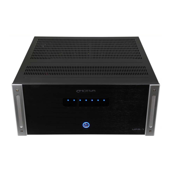
UPA-7 Front Panel Layout 1. Front Panel LED Display The front panel display contains Status LED lighting to indicate the condition of the UPA-7. • NO LED = Amplifier is OFF • BLUE LED = Normal Operation • FLASHING RED LED = Fault Condition - see “Troubleshooting” section for details. 2. -
Page 11: Upa-7 Rear Panel Layout
3. Remote Trigger Input - This 3.5mm jack accepts a 5-12 volt input for remote activation of the UPA-7. This mates directly with the Emotiva processor trigger out. If building your own cable, center is positive and outer shield is negative. -
Page 12: Installation And Connections
15 amperes maximum. Most DVD players and other source components are fairly low current items. The Emotiva UPA-7 requires a minimum of 10 amperes @ 115volts or 5 amperes @ 230 volts. It should be sufficient to allow the other devices such as... -
Page 13: Input Connection Considerations
Input Connection Considerations Whenever possible, keep preamplifier level audio cables away from electrical power cords by at least a few inches. It’s more important with amplifiers as the AC power cords are carrying much more current than other source and preamplifier components, which means there is a larger degree of noise or “hum” potential with the amplifier power cord in close proximity. -
Page 14: 12V Trigger Connections
12V Trigger Connections The 12 VDC trigger connection shown can be used to turn the amplifier on when the preamplifier turns on. This trigger will actually trigger with any switched DC Voltage from 5-12 VDC; however, the majority of home theater components use a standard 12 VDC trigger connection for this function. -
Page 15: Connection Diagrams
Connection Diagrams Connection using a 7 Channel Preamp/Processor... -
Page 16: Connection Using A 7 Channel Preamp/Processor With Audio Devices And Speakers
Connection using a 7 Channel Preamp/Processor with Audio Devices and Speakers This configuration shows the UPA-7 driving full range channels. This type of configuration is ideal for enthusiasts who have (or will) make their own self-powered subwoofer and want to utilize an amplifier that will drive the entire system in one chassis. -
Page 17: Series And Parallel Speaker Connections
Series and Parallel Speaker Connections Series Connections Whenever connecting more than one speaker per channel to an amplifier (regardless of the brand), you must consider the way in which the amplifier will be impacted by adding the additional speaker(s). Additionally, speakers with dual voice coils also apply to this consideration. Two voice coils in a single speaker also cause different reactions from an amplifier depending on the way in which they connect to the amplifier. -
Page 18: Parallel Connections
Parallel Connections A parallel circuit is established when voice coils are connected in a way that there are multiple paths for audio signals to flow “in” and multiple paths for audio signals to flow “out”. When speakers are connected in parallel, the total resistance at the amplifier is proportionally divided based on the value of each individual voice coil resistance. - Page 19 of different nominal impedances and/or different bandwidths are used, there are many other acoustic problems that come into play in addition to complex impedance at the amplifier’s speaker output terminals. If you must use multiple speakers on any individual amplifier channel, please use speakers as close to identical as possible.
-
Page 20: Troubleshooting Guide
Troubleshooting Guide The Emotiva UPA-7 is expertly designed and built to provide years of trouble-free performance. Most problems that occur can usually be solved by checking your setup or making sure that the audio and video components connected to the amplifier are on and fully operational. -
Page 21: Poor Bass Performance From Full Range Speakers Connected To The Upa-7
Plug the amplifier into an un-switched AC outlet, and use the 3.5mm Trigger Input connection with a trigger between 5-12VDC from the source unit or preamplifier (such as the Emotiva UMC-1 Preamplifier/Processor). This should allow the amplifier to turn on and off silently. -
Page 22: Other Probable Causes Of Noise
Ground loop isolators are available for audio lines and video devices. If you need assistance, contact Emotiva. Although this is not always an ideal solution, the grounding differences between certain home entertainment components sometimes require ground loop isolators. This is the exception rather than the rule. -
Page 23: Problems With The Whole A/V System
DC at output is a possible fault condition that is equipment related and requires technical assistance. Please contact Emotiva if you have repeated problems causing the RED front panel light to flash that are NOT thermal or short circuit related. -
Page 24: Technical Specifications
TECHNICAL SPECIFICATIONS Number of Channels: 7 Topology: Fully Discrete, Dual Differential, High Current, Short Signal Path Class A/B Power output (all channels driven): 185 watts RMS @ 4 ohm (0.1% THD) 125 watts RMS @ 8 ohm (0.1% THD) Power output (1 channel driven): 300 watts RMS @ 4 ohm (0.1% THD) 180 watts RMS @ 8 ohm (0.1% THD) Power Band Response: 20 Hz to 20 KHz with less than .05db deviation at rated power... -
Page 25: Limited Warranty
Limited Warranty The Emotiva UPA-7 has been created to perform flawlessly for many years. As a result of this quality and craftsmanship, Emotiva offers the following warranty to owners of the UPA-7. Emotiva Audio warranties the UPA-7 to be free from defects in materials and workmanship for a period of five years from the original date of purchase. -
Page 26: Emotiva Disclosure
Emotiva Disclosure Copyright 2009 Emotiva All Rights Reserved. Emotiva reserves the right to make improvements to its products at any time. Therefore, the specifications of the product and the specific details of this manual are subject to change at any time.
Need help?
Do you have a question about the UPA-7 and is the answer not in the manual?
Questions and answers