Table of Contents
Advertisement
TZ77XE3/TZ75XE3 S etup Man ual
FCC Information and Copyright
This equipment has been tested and found to comply with the limits of a Class
B digital device, pursuant to Part 15 of the FCC Rules. These limits are designed
to provide reasonable protection against harmful interference in a residential
installation. This equipment generates, uses, and can radiate radio frequency
energy and, if not installed and used in accordance with the instructions, may
cause harmful interference to radio communications. There is no guarantee
that interference will not occur in a particular installation.
The vendor makes no representations or warranties with respect to the
contents here and specially disclaims any implied warranties of merchantability
or fitness for any purpose. Further the vendor reserves the right to revise this
publication and to make changes to the contents here without obligation to
notify any party beforehand.
Duplication of this publication, in part or in whole, is not allowed without first
obtaining the vendor's approval in writing.
The content of this user's manual is subject to be changed without notice and
we will not be responsible for any mistakes found in this user's manual. All the
brand and product names are trademarks of their respective companies.
Dichiarazione di conformità
sintetica
Ai sensi dell'art. 2 comma 3 del D.M.
275 del 30/10/2002
Si dichiara che questo prodotto è
conforme alle normative vigenti e
soddisfa i requisiti essenziali richiesti
dalle direttive
2004/108/CE, 2006/95/CE e
1999/05/CE
quando ad esso applicabili
Short Declaration of conformity
We declare this product is complying
with the laws in force and meeting all
the essential requirements as specified
by the directives
2004/108/CE, 2006/95/CE and
1999/05/CE
whenever these laws may be applied
Advertisement
Table of Contents

Related Manuals for Biostar TZ77A


Summary of Contents for Biostar TZ77A
- Page 1 TZ77XE3/TZ75XE3 S etup Man ual FCC Information and Copyright This equipment has been tested and found to comply with the limits of a Class B digital device, pursuant to Part 15 of the FCC Rules. These limits are designed to provide reasonable protection against harmful interference in a residential installation.
-
Page 2: Table Of Contents
Table of Contents Chapter 1: Introduction ........1 Before You Start..................1 Package Checklist ..................1 Motherboard Features ................2 Rear Panel Connectors................4 Motherboard Layout ................. 5 Chapter 2: Hardware Installation ......6 Installing Central Processing Unit (CPU) ..........6 FAN Headers .................... -
Page 3: Chapter 1: Introduction
TZ7 7 X E3 / TZ7 5 X E3 CHAPTER 1: INTRODUCTION EFORE TART Thank you for choosing our product. Before you start installing the motherboard, please make sure you follow the instructions below: Prepare a dry and stable working environment with sufficient lighting. -
Page 4: Motherboard Features
Motherboard Manual OTHERBOARD EATURES SPEC Supports Execute Disable Bit / Enhanced Intel Socket 1155 SpeedStep® / Intel Architecture-64 / Extended Intel Core i7 / i5 / i3 / Pentium / Celeron Memory 64 Technology / Virtualization Technology / processor Hyper Threading Intel Z77 (TZ77XE3) Chipset Intel Z75 (TZ75XE3) - Page 5 Connect to USB3.0 devices Audio Jack Provide Audio-In/Out and Mic. connection Board Size 244 (W) x 305 (L) mm Biostar reserves the right to add or remove support OS Support Windows XP / Vista / 7 for any OS with or without notice...
-
Page 6: Rear Panel Connectors
Motherboard Manual ANEL ONNECTORS PS/2 Keyboard USB2.0X2 HDMI DVI-D USB3.0X2 USB2.0X2 Line In Center Rear Line Out Side Mic In NOTE: USB3.0 ports (only supported by Windows 7) are backward compatible with USB2.0/USB1.X devices. NOTE: Maximum resolution: HDMI: 1920 x 1200 @60Hz, compliant with HDMI 1.4a DVI: 1920 x 1200 @60Hz VGA: 2048 x 1536 @75Hz NOTE:... -
Page 7: Motherboard Layout
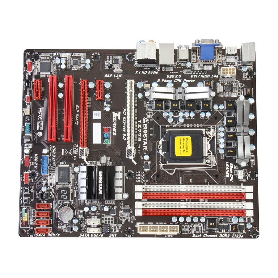
TZ7 7 X E3 / TZ7 5 X E3 OTHERBOARD AYOUT USB_KBMS1 CPU_FAN1 ATXPWR2 Socket 1155 CPU 1 USB3_0 RJ45USB1 AUDIO1 SYS_FAN2 ATXPWR1 PEX16_1 PEX1_1 Intel Z77/ PEX1_2 BIOS F_AUDIO1 PEX16_2 JCMOS1 CO DE C PCI1 BAT1 Super PCI2 JFRONT_USB3_1 SATA6 SATA4 SATA2... -
Page 8: Chapter 2: Hardware Installation
Motherboard Manual CHAPTER 2: HARDWARE INSTALLATION (CPU) NSTALLING ENTRAL ROCESSING Notice: Remove Pin Cap before installation, and make good preservation for future use. When the CPU is removed, cover the Pin Cap on the empty socket to ensure pin legs won’t be damaged. The motherboard might equip with two different types of pin cap. - Page 9 TZ7 7 X E3 / TZ7 5 X E3 Step 3: Hold processor with your thumb and index fingers, oriented as shown. Align the notches with the socket. Lower the processor straight down without tilting or sliding the processor in the socket. Step 4: Hold the CPU down firmly, and then lower the lever to locked position to complete the installation.
-
Page 10: Fan Headers
Motherboard Manual FAN H EADERS These fan headers support cooling-fans built in the computer. The fan cable and connector may be different according to the fan manufacturer. Connect the fan cable to the connector while matching the black wire to pin#1. -
Page 11: Installing System Memory
TZ7 7 X E3 / TZ7 5 X E3 NSTALLING YSTEM EMORY A. Memory Modules Unlock a DIMM slot by pressing the retaining clips outward. Align a DIMM on the slot such that the notch on the DIMM matches the break on the Slot. - Page 12 Motherboard Manual B. Memory Capacity DIMM Socket Total Memory DDR3 Module Location Size DDR3_A1 512MB/1GB/2GB/4GB/8GB DDR3_A2 512MB/1GB/2GB/4GB/8GB Max is 32GB. DDR3_B1 512MB/1GB/2GB/4GB/8GB DDR3_B2 512MB/1GB/2GB/4GB/8GB C. Dual Channel Memory Installation Please refer to the following requirements to activate Dual Channel function: Install memory module of the same density in pairs, shown in the table.
-
Page 13: Connectors And Slots
TZ7 7 X E3 / TZ7 5 X E3 ONNECTORS AND LOTS SATA1/SATA2: Serial ATA3.0 Connectors The motherboard has a PCI to SATA Controller with 2 channels SATA interface, it satisfies the SATA 3.0 spec and with transfer rate of 6.0Gb/s. Assignment Ground Ground... - Page 14 Motherboard Manual PEX16_1/ PEX16_2: PCI-Express Gen3 x16 (x16 / x8) (Nvidia SLI and AMD CrossFireX) Slots PCI-Express 3.0 compliant. Maximum theoretical realized bandwidth of 16GB/s simultaneously per direction, for an aggregate of 32GB/s totally. The speed of PEX16_1 is x16, or x8 when SLI / CFX is enabled; the speed of PEX16_2 is x8.
- Page 15 TZ7 7 X E3 / TZ7 5 X E3 PCI1/PCI2: Peripheral Component Interconnect Slots This motherboard is equipped with 2 standard PCI slots. PCI stands for Peripheral Component Interconnect, and it is a bus standard for expansion cards. This PCI slot is designated as 32 bits. PCI 1 PCI2 ATXPWR2: ATX Power Source Connectors...
- Page 16 Motherboard Manual ATXPWR1: ATX Power Source Connector This connector allows user to connect 24-pin power connector on the ATX power supply. Assignment Assignment +3.3V +3.3V -12V +3.3V Ground Ground PS_ON Ground Ground Ground Ground Ground PW_OK Standby Voltage+5V +12V +12V Ground +3.3V Note:...
-
Page 17: Chapter 3: Headers & Jumpers Setup
TZ7 7 X E3 / TZ7 5 X E3 CHAPTER 3: HEADERS & JUMPERS SETUP OW TO ETUP UMPERS The illustration shows how to set up jumpers. When the jumper cap is placed on pins, the jumper is “close”, if not, that means the jumper is “open”. - Page 18 Motherboard Manual F_USB1/F_USB2: Headers for USB 2.0 Ports at Front Panel These headers allow user to connect additional USB cable on the PC front panel, and also can be connected with internal USB devices, like USB card reader. Assignment +5V (fused) +5V (fused) USB- USB-...
- Page 19 TZ7 7 X E3 / TZ7 5 X E3 F_AUDIO1: Front Panel Audio Header This header allows user to connect the front audio output cable with the PC front panel. This header supports HD and AC’97 audio front panel connector. Assignment Mic Left in Ground...
-
Page 20: Clear Cmos Procedures
Motherboard Manual JCMOS1: Clear CMOS Header Placing the jumper on pin2-3 allows user to restore the BIOS safe setting and the CMOS data. Please carefully follow the procedures to avoid damaging the motherboard. Pin 1-2 Close: Normal Operation (default). Pin 2-3 Close: Clear CMOS data. - Page 21 TZ7 7 X E3 / TZ7 5 X E3 BIOS POST Code/CPU Temperature Indicator This indicator will show POST code while booting. After the booting sequence, it will show current CPU temperature through hexadecimal figure. Please refer to Chapter 6.3 for all the BIOS POST codes. On-Board Buttons There are 2 on-board buttons.
-
Page 22: Chapter 4: Raid / Ahci Functions
Motherboard Manual CHAPTER 4: RAID / AHCI FUNCTIONS PERATING YSTEM SATA CHIP Controller Supporting OS Configuration Intel Z77 / Z75 AHCI Windows XP SP2 (32 and 64 bit) SATA1/SATA2/ Windows Vista SP2 (32 and 64 bit) SATA3/SATA4/ Windows 7 (32 and 64 bit) SATA5/SATA6 Intel Z77 / Z75 RAID... -
Page 23: Raid Arrays
TZ7 7 X E3 / TZ7 5 X E3 Enable RAID / AHCI Driver when installing Windows 7/Vista Before you start Windows installation, copy the proper files for the Windows version to any USB storage. Windows Vista 32 Windows Vista 64 Windows 7 32 Windows 7 64 SATA1/SATA2/... -
Page 24: How Raid Works
Motherboard Manual RAID W ORKS RAID 0: The controller “stripes” data across multiple drives in a RAID 0 array system. It breaks up a large file into smaller blocks and performs disk reads and writes across multiple drives in parallel. The size of each block is determined by the stripe size parameter, which you set during the creation of the RAID set based on the system environment. - Page 25 TZ7 7 X E3 / TZ7 5 X E3 RAID 1: Every read and write is actually carried out in parallel across 2 disk drives in a RAID 1 array system. The mirrored (backup) copy of the data can reside on the same disk or on a second redundant drive in the array.
- Page 26 Motherboard Manual RAID 10: RAID 1 drives can be stripped using RAID 0 techniques. Resulting in a RAID 10 solution for improved resiliency, performance and rebuild performance. Features and Benefits Drives: Minimum 4, and maximum is 6 or 8, depending on the platform. ...
- Page 27 TZ7 7 X E3 / TZ7 5 X E3 RAID 5: RAID 5 stripes both data and parity information across three or more drives. It writes data and parity blocks across all the drives in the array. Fault tolerance is maintained by ensuring that the parity information for any given block of data is placed on a different drive from those used to store the data itself.
-
Page 28: Smart Response Technology
Motherboard Manual NTEL MART ESPONSE ECHNOLOGY With Intel(R) Smart Response Technology, the performance of RAID with an Intel SSD drive can be improved better. This function is only for TZ77XE3. Installing Smart Response Technology 1. Install RAID drives (RAID 0, 1, 5) and an Intel SSD. 2. -
Page 29: Chapter 5: T-Series Uefi Bios & Software
TZ7 7 X E3 / TZ7 5 X E3 CHAPTER 5: T-SERIES UEFI BIOS & SOFTWARE UEFI BIOS ERIES T-Series UEFI BIOS Features Overclocking Navigator Engine (O.N.E.) Self Recovery System (S.R.S) Smart Fan Function BIO-Flasher: Update UEFI BIOS file from USB Flash Drive !! WARNING !! For better system performance, the UEFI BIOS firmware is being continuously updated. - Page 30 Motherboard Manual NOTE Overclock is an optional process, but not a “must-do” process; it is not recommended for inexperienced users. Therefore, we will not be responsible for any hardware damage which may be caused by overclocking. We also would not guarantee any overclocking performance. B.
- Page 31 TZ7 7 X E3 / TZ7 5 X E3 CPU Smart FAN This item allows you to control the CPU Smart Fan function. CPU FAN Calibrate Press [ENTER] to calibrate CPU FAN. Control Mode This item provides several operation modes of the fan. Fan Ctrl OFF(℃) When CPU temperature is lower than this value, the CPU fan will keep lowest RPM.
-
Page 32: T-Series Software
Motherboard Manual ERIES OFTWARE Installing T-Series Software 6. Insert the Setup DVD to the optical drive. The driver installation program would appear if the Auto-run function has been enabled. 7. Select Software Installation, and then click on the respective software title. - Page 33 TZ7 7 X E3 / TZ7 5 X E3 The CPU tab provides information on the CPU and motherboard. The Memory tab provides information on the memory module(s). You can select memory module on a specific slot to see its information. The OC Tweaker tab allows you to change system clock settings and voltages settings.
- Page 34 Motherboard Manual 3 Pre-set Modes: V6, V12, AUTO for different overclocking experience. The HW Monitor tab allows you to monitor hardware voltage, fan speed, and temperature. Besides, you also can set related values for CPU Smart Fan.
- Page 35 “Live Update.” Green Power II Utility BIOSTAR G.P.U II (Green Power Utility) is a new function. The utility enhances energy efficiency by disabling extra phases while CPU is on light loading; it features 4+1 power phases, current power saving, and toal power saving. This tool integrates a friendly GUI to monitor your CPU Usage, CPU Watt, and CPU Temperature.
- Page 36 Motherboard Manual G.P.U Mode Setting This utility provides five modes, upon your requirements, to improve system performance or to save power consumption. Note: Even if the modes saving more power consumption are chosen, the system still can keep excellent performance. Auto Phase Mode System switches the mode automatically according to current system loading condition.
- Page 37 TZ7 7 X E3 / TZ7 5 X E3 Guide of Lucid VIRTU MVP Installation With Lucid VIRTU MVP solution, the resource and performance of graphics can be integrated so that user can choose the suitable mode for the requirement. System Requirements CPU: CPU with integrated graphics support Chipset: Any chipset with integrated graphics output...
- Page 38 Motherboard Manual Software Installation 1. Install VGA Driver and VIRTU MVP Software. 2. If for some reason auto-activation process fails, or the internet is not available for 30 days, user will have to manually activate Virtu Universal MVP by pressing “Activate”...
- Page 39 TZ7 7 X E3 / TZ7 5 X E3 eHot-Line (Optional) eHot-Line is a convenient utility that helps you to contact with our Tech-Support system. This utility will collect the system information which is useful for analyzing the problem you may have encountered, and then send these information to our tech-support department to help you fix the problem.
- Page 40 Motherboard Manual Enter the file name and then click “Save”. Your system information will be saved to a .txt file. Open the saved .txt file, you will see your system information including motherboard/BIOS/CPU/video/ device/OS information. This information is also concluded in the sent mail.
- Page 41 TZ7 7 X E3 / TZ7 5 X E3 BIOS Update BIOS Update is a convenient utility which allows you to update your motherboard BIOS under Windows system. Show current BIOS information AWARD BIOS AMI BIOS Clear CMOS function (Only for AWARD BIOS) Save current BIOS to a .bin file Update BIOS...
- Page 42 Motherboard Manual <Update BIOS> Before doing this, please download the proper BIOS file from the website. For AWARD BIOS, update BIOS procedure should be run with Clear CMOS function, so please check on Clear CMOS first. Then click Update BIOS button, a dialog will show for asking you backup current BIOS.
- Page 43 TZ7 7 X E3 / TZ7 5 X E3 (Optional) BIOScreen Utility This utility allows you to personalize your boot logo easily. You can choose JPG or BMP as your boot logo so as to customize your computer. Please follow the following instructions to update boo logo: 1.
-
Page 44: Chapter 6: Useful Help
Motherboard Manual CHAPTER 6: USEFUL HELP RIVER NSTALLATION After you installed your operating system, please insert the Fully Setup Driver DVD into your optical drive and install the driver for better system performance. You will see the following window after you insert the DVD The setup guide will auto detect your motherboard and operating system. -
Page 45: Extra Information
TZ7 7 X E3 / TZ7 5 X E3 XTRA NFORMATION CPU Overheated If the system shutdown automatically after power on system for seconds, that means the CPU protection function has been activated. When the CPU is over heated, the motherboard will shutdown automatically to avoid a damage of the CPU, and the system may not power on again. -
Page 46: Ami Bios Post Code
Motherboard Manual AMI BIOS P Checkpoint Description Disable NMI, Parity, video for EGA, and DMA controllers. Initialize BIOS, POST, Runtime data area. Also initialize BIOS modules on POST entry and GPNV area. Initialized CMOS as mentioned in the Kernel Variable "wCMOSFlags."... - Page 47 TZ7 7 X E3 / TZ7 5 X E3 Checkpoint Description Displaying sign-on message, CPU information, setup key message, and any OEM specific information. Initializes different devices through DIM. See DIM Code Checkpoints section of document for more information. USB controllers are initialized at this point.
-
Page 48: Troubleshooting
Motherboard Manual 6.4 T ROUBLESHOOTING Probable Solution There is no power in the system. Make sure power cable is Power LED does not shine; the securely plugged in. fan of the power supply does not Replace cable. work Contact technical support. Indicator light on keyboard does not shine. - Page 49 TZ7 7 X E3 / TZ7 5 X E3 This page is intentionally left blank.
-
Page 50: Appendix: Spec In Other Languages
Motherboard Manual APPENDIX: SPEC IN OTHER LANGUAGES ERMAN Spezifikationen Unterstützt Execute Disable Bit / Enhanced Intel Socket 1155 SpeedStep® / Intel Architecture-64 / Extended Intel Core i7 / i5 / i3 / Pentium / Celeron Memory 64 Technology / Virtualization Technology / Prozessoren Hyper Threading Intel Z77 (TZ77XE3) - Page 51 Rückseiten-E DVI-Anschluss LAN-Anschluss USB2.0-Anschluss USB3.0-Anschluss Audioanschluss Platinengröße 244 mm (B) X 305 mm (L) Biostar behält sich das Recht vor , ohne Ankündigung OS-Unterstüt Windows XP / Vista / 7 die Unterstützung für ein Betriebssystem zung hinzuzufügen oder zu entfernen.
-
Page 52: French
Motherboard Manual RENCH SPEC Prend en charge les technologies d'exécution de bit Socket 1155 de désactivation / Intel SpeedStep® optimisée/ Processeurs Intel Core i7 / i5 / i3 / Pentium / d'architecture Intel 64 / de mémoire étendue 64 / de Celeron virtualisation / Hyper Threading Intel Z77 (TZ77XE3) - Page 53 Port USB3.0 Fiche audio Dimensions 244 mm (l) X 305 mm (H) de la carte Biostar se réserve le droit d'ajouter ou de supprimer Support SE Windows XP / Vista / 7 le support de SE avec ou sans préavis...
-
Page 54: Italian
Motherboard Manual TALIAN SPECIFICA Supporto di Execute Disable Bit / Enhanced Socket 1155 Intel SpeedStep® / Architettura Intel 64 / Processore Intel Core i7 / i5 / i3 / Tecnologia Extended Memory 64 / Tecnologia Pentium / Celeron Virtualization / Hyper Threading Intel Z77 (TZ77XE3) Chipset Intel Z75 (TZ75XE3) - Page 55 Porta USB3.0 Connettore audio Dimension 244 mm (larghezza) x 305 mm i scheda (altezza) Biostar si riserva il diritto di aggiungere o Sistemi operativi Windows XP / Vista / 7 rimuovere il supporto di qualsiasi sistema supportati operativo senza preavviso.
-
Page 56: Spanish
Motherboard Manual PANISH Especificación Admite Bit de deshabilitación de ejecución / Intel Socket 1155 SpeedStep® Mejorado / Intel Architecture-64 / Procesador Intel Core i7 / i5 / i3 / Pentium / Tecnología Extended Memory 64 / Tecnología de Celeron virtualización / Hyper Threading Conjunto de Intel Z77 (TZ77XE3) Intel Z75 (TZ75XE3) - Page 57 Tamaño de 244 mm. (A) X 305 Mm. (H) la placa Soporte de Biostar se reserva el derecho de añadir o retirar el Windows XP / Vista / 7 sistema soporte de cualquier SO con o sin aviso previo. operativo...
-
Page 58: Portuguese
Motherboard Manual ORTUGUESE ESPECIFICAÇÕES Suporta as tecnologias Execute Disable Bit / Socket 1155 Enhanced Intel SpeedStep® / Intel Arquitecture -64 Processador Intel Core i7 / i5 / i3 / Pentium / / Extended Memory 64 / Virtualization / Hyper Celeron Threading Intel Z77 (TZ77XE3) Chipset... - Page 59 Tomada de áudio Tamanho 244 mm (L) X 305 mm (A) da placa Sistemas A Biostar reserva-se o direito de adicionar ou Windows XP / Vista / 7 remover suporte para qualquer sistema operativo operativos com ou sem aviso prévio.
-
Page 60: Polish
Motherboard Manual OLISH SPEC Obsługa Execute Disable Bit / Enhanced Intel Socket 1155 SpeedStep® / Intel Architecture-64 / Extended Procesor Intel Core i7 / i5 / i3 / Pentium / Procesor Memory 64 Technology / Virtualization Technology / Celeron Hyper Threading Intel Z77 (TZ77XE3) Chipset Intel Z75 (TZ75XE3) - Page 61 Port DVI Port LAN Port USB2.0 Port USB3.0 Gniazdo audio Wymiary 244 mm (S) X 305 mm (W) płyty Obsluga Biostar zastrzega sobie prawo dodawania lub systemu Windows XP / Vista / 7 odwoływania obsługi dowolnego systemu operacyjne operacyjnego bez powiadomienia.
-
Page 62: Russian
Motherboard Manual USSIAN СПЕЦ Поддержка технологий Execute Disable Bit / Socket 1155 (центральн Enhanced Intel SpeedStep® / Intel Architecture-64 Процессор Intel Core i7 / i5 / i3 / Pentium / / Extended Memory 64 Technology / технологии ый Celeron виртуализация / Hyper Threading процессор) Набор... - Page 63 ввода-выв USB3.0-порт ода Гнездо для подключения наушников Размер 244 мм (Ш) X 305 мм (В) панели Biostar сохраняет за собой право добавлять или Поддержка Windows XP / Vista / 7 удалять средства обеспечения для OS с или без предварительного уведомления.
-
Page 64: Arabic
Motherboard Manual RABIC اﻟﻤﻮاﺻﻔﺎت ﺗﺪﻋﻢ ﺗﻘﻨﻴﺎتExecute Disable Bit / Enhanced Intel Socket 1155 SpeedStep® / Intel Architecture-64 / Extended اﻟﻤﻌﺎﻟﺠﺔ وﺣﺪة ﻣﻌﺎﻟﺠﺎتIntel Core i7 / i5 / i3 / Pentium / Memory 64 Technology / Virtualization Technology / اﻟﻤﺮآﺰیﺔ Celeron ﺼﻞ... -
Page 65: Smart Fan
اﻟﺨﻠﻔﻴﺔ اﻟﻠﻮﺣﺔ ﻋﺪد USB2.0 ﻣﻨﺎﻓﺬ ﻋﺪد USB3.0 ﻣﻨﺎﻓﺬ ﻋﺪد ﻣﻘﺒﺲ ﺹﻮت ارﺗﻔﺎع ﻣﻢ ﻋﺮض ﻣﻢ اﻟﻠﻮﺣﺔ ﺣﺠﻢ ﺗﺤﺘﻔﻆBiostar ﺑﺪون أو ﺑﺈﺧﻄﺎر ﻐﻴﻞ ﺗﺸ ﻧﻈﺎم ﻷي اﻟﺪﻋﻢ إزاﻟﺔ أو إﺿﺎﻓﺔ ﻓﻲ ﺑﺤﻘﻬﺎ Windows XP / Vista / 7 اﻟﺘﺸﻐﻴﻞ أﻧﻈﻤﺔ... -
Page 66: Japanese
Motherboard Manual APANESE 仕様 Execute Disable Bit / Enhanced Intel SpeedStep® / Socket 1155 Intel Architecture-64 / Extended Memory 64 Intel Core i7 / i5 / i3 / Pentium / Celeron プロ Technology / Virtualization Technology / Hyper セッサ Threadingをサポートします Intel Z77 (TZ77XE3) チップセット... - Page 67 CMOSクリアヘッダ 各コネクタは2つのフロントパネルUSB2.0ポートをサポ USB2.0コネクタ ートします 各コネクタは2つのフロントパネルUSB3.0ポートをサポ USB3.0コネクタ ートします 消費者IRコネクタ シリアルポート S/PDIFアウトコネクタ デジタルオーディオアウト機能をサポートします 電源コネクタ(24ピン) 電源コネクタ(8ピン) PS/2キーボード HDMIポート VGAポート DVI-Dポート 背面パネル LANポート USB2.0ポート USB3.0ポート オーディオジャック ボードサイズ 244 mm (幅) X 305 mm (高さ) Biostarは事前のサポートなしにOSサポートを追加または OSサポート Windows XP / Vista / 7 削除する権利を留保します。 2012/05/09...
Need help?
Do you have a question about the TZ77A and is the answer not in the manual?
Questions and answers