Table of Contents
Advertisement
Advertisement
Table of Contents
Troubleshooting

Related Manuals for Texas Instruments Extensa 570x Series


Summary of Contents for Texas Instruments Extensa 570x Series
- Page 1 Maintenance Manual Extensa 57x Series Notebook Computers 9811323-0001 May 1996...
- Page 2 Texas Instruments Incorporated P.O. Box 6102, M/S 3255 Temple, Texas 76503 Extensa and DockMate are trademarks of Texas Instruments. The icons in the Windows Notebook and Startup groups are copyrighted by Texas Instruments. Lotus is a trademark of Lotus Development Corporation.
-
Page 3: Table Of Contents
Contents Preface 1 General Description 1.1 ..Introduction ....... 1-1 1.2 . - Page 4 2.5.1 . . . Installing an External Keyboard/Mouse ..2-4 2.5.2 . . . Installing External Parallel Printer ... . 2-6 2.5.3 . . . Installing External Serial Port Device ..2-7 2.5.4 .
- Page 5 4.2.4 . . . Hard Disk Subsystem ..... 4-6 4.2.5 . . . Floppy Diskette Drive Subsystem ... . . 4-7 4.2.6 .
- Page 6 6.5.7 . . . Removing and Replacing the LCD Status ..Assembly ....... 6-11 6.5.8 .
-
Page 7: General Description
Preface Introduction This manual provides installation, operation and servicing data for the Extensa 57x Series Notebook Computers. Intended Audience This manual is primarily intended for use by qualified service technicians but contains information useful to non-technical users. Contents This manual contains six sections and reference appendices including: Section 1: General Description —... - Page 8 Other Manuals About the System The following documents provide additional information related to the Extensa 57x Series Notebooks: Extensa 57x Series Notebook Computer User’s Reference Manual, contains reference information regarding the Extensa 57x series software. ® Windows 95 Help (online) PC-Doctor Help and Technical Reference (online) Ordering Parts and Supplies To order a copy of any TI publication or to order option kits, spare parts or...
-
Page 9: Product Models
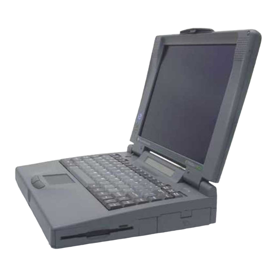
General Description Introduction This manual contains field and factory level servicing information for the Texas Instruments Extensa 57x Series of Notebook Computers (Figure 1-1). This section provides a general overview and specifications for the Extensa 57x Series Notebook Computers. Figure 1-1 Extensa 57xSeries Notebook Computer... -
Page 10: International Product Versions
Table 1-1 Extensa 57x Series Notebook Computers Features Model Model Model Model 570CD 575CD 570CDT 575CDT 11.3" Dual Scan, SVGA Color LCD 10.4" Active Matrix (TFT), SVGA Color LCD 1.44 MB Floppy Drive Module CD-ROM Drive Module Windows 95 Application Software 16-Bit Stereo Sound HDD 810 Million Bytes HDD 1200 Million Bytes... -
Page 11: Product Overview
Product Overview All members of the Extensa 57x Series are high performance notebooks powered by the Pentium Processor and Windows 95 Operating System software. As a standard feature, all members of the Extensa 57x family also contain the following features: 100 MHz Pentium Processor with 16K Internal Cache Memory. - Page 12 AC Adapter with autosensing (100 VAC to 240 VAC, 50 to 60 Hz); 36 Watts of DC output power. 8.4 Volt, 4200 mAH capacity, Nickel-Metal Hydride (NiMH) primary battery pack. Provisions for secondary 10.8 Volt Lithium-Ion Battery Pack in Floppy Drive cavity (if Floppy Drive or CD ROM Player not installed).
-
Page 13: External Ports
1.4.1 External Ports As shown in Figure 1-3, the notebook computer contains the following external ports: Serial Infrared (SIR) Port for wireless connection with a similarly equipped printer or computer 9-Pin Serial Port for attaching any RS-232 type serial device to the Notebook 15-Pin External VGA Monitor Port for attaching an external monitor 6-Pin PS/2 Port to attach an external Keyboard or Mouse... -
Page 14: Glidepad Pointing Device
1.4.2 Glidepad Pointing Device All members of the Extensa 57x family feature a built-in glidepad pointing device located near the center of the keyboard’s palmrest. With light finger pressure, the cursor can quickly be positioned to the desired point; a quick double tap on the glidepad and you have selected an object. -
Page 15: Standard Power Features
Note: The Extensa Series Notebook Computer User’s Reference Manual con- tains descriptions of keyboard special function keys. NumLk F1 1 Prt Sc Scroll Pause F1 0 Sys Rq Lock Break & Backspace Home PgUp Home PgUp Caps Enter P g D n Lock Pg On En d... -
Page 16: Wireless Connection With Serial Infrared Port
1.4.5 Wireless Connection With Serial Infrared Port The Extensa Series notebooks are equipped with a Serial Infrared (IR) port that offers wireless communication with a variety of IRDA compliant devices made by other manufacturers. Note: Prior to communicating with an external device equipped with a serial infrared interface, the appropriate third-party drivers must be installed on your notebook. -
Page 17: Standard Test Features
Standard Test Features The Extensa Series Notebook Computers use modular design and built-in test features to reduce the mean time to repair. A power on self test program automatically verifies the operational state of the primary circuits. Also, the notebook contains a powerful suite of diagnostic tests called PC-Doctor, (described in detail in Appendix B) that can perform additional levels of diagnostic testing. -
Page 18: Cover-Display Assembly
Display Assembly Keyboard Assembly Status LCD Assembly Glidepad Assembly Power Supply Board IR/Sound Board Display Assembly Floppy Drive/CD-ROM Main Board Display Cable Interface Board Inverter Board Figure 1-6 Notebook Assemblies 1.6.1 Cover-Display Assembly The Cover-Display Assembly contains the LCD screen and associated high voltage power supply and video circuitry. -
Page 19: System Base Assembly
1.6.2 System Base Assembly As shown in Figure 1-6, the majority of the notebook’s field replaceable units (FRUs) are located in the system base assembly. These FRUs include: Main Board Assembly Hard Disk Drive Assembly Up to two Dual Inline Memory Modules LCD Status Assembly Floppy Drive Module IR/Sound Board Assembly... - Page 20 Table 1-3 Extensa 57x Notebook Features Models Specifications Models 570CD/575CD 570CDT/575CDT Processor Pentium 100 MHz Pentium 100 MHz Memory: Standard: 8 MB 8 MB Maximum: 40 MB 40 MB Cache: 256 KB L2 Cache 256 KB L2 Cache Display LCD Type: 11.3 inch, SVGA, Dual 10.4 inch, SVGA, Dual Scan Color...
-
Page 21: Agency Approvals
Models Specifications Models 570CD/575CD 570CDT/575CDT Battery Pack Nickel-Metal Hydride, Nickel-Metal Hydride, optional Lithium-Ion optional Lithium-Ion secondary battery pack secondary battery pack option option Sound Features 16-bit Stereo Sound, Audio 16-bit Stereo Sound, in/out and Microphone In Audio in/out and jacks, built in stereo Microphone In jacks, speakers and microphone built in stereo speakers... -
Page 22: Installation
Installation Introduction This section contains unpacking and preparation for use instructions for the Extensa 57x Series Notebook Computers. Unpacking Instructions Unpack the computer using the following instructions: Carefully cut the tape that seals the top flap of the shipping carton. Remove the computer and the accessories from the main shipping carton. -
Page 23: Installing Pcmcia Options
Ensure that the notebook is powered off and that the AC Adapter and internal battery pack(s) is (are) removed from the notebook. Remove the Expansion RAM Module (Dual Inline Memory Module or DIMM) from its shipping container. Turn the Notebook over and locate the RAM Access Door (held in place by two screws). -
Page 24: Installing External Devices
be installed in the removable Floppy/CD-ROM bay. Two switches that used to remove devices from the option bay are physically located on the bottom of the Notebook. The left-most switch controls removal of the Primary Battery Pack and the right-most switch controls removal of the device installed in the Floppy/CD-ROM/Secondary Battery bay. -
Page 25: Installing An External Keyboard/Mouse
PS/2 Port Serial Connector for Infrared External External Expansion Port VGA Port System Serial Parallel Audio Line Port Port In/Out/Mic In Figure 2-1 I/O Connector Locations 2.5.1 Installing an External Keyboard/Mouse As shown in Figure 2-2, the notebook has one external PS/2 port on the rear of the Notebook for installing a PS/2 compatible device (keyboard, mouse, etc.). - Page 26 Figure 2-2 PS/2 Port Assignments/Pinouts To install an external keyboard or external PS/2 mouse on the notebook, use the following procedure: Ensure that the notebook is powered off. Locate the external PS/2 port at the rear of the notebook (refer to Figure 2-2).
-
Page 27: Installing External Parallel Printer
2.5.2 Installing External Parallel Printer The Notebook is equipped with a bidirectional, ECC/EPP compatible, 25-pin parallel printer port. The connector pinouts and connector location are shown in Figure 2-3. PARALLEL PORT PINOUTS SIGNAL STROBE DATA BIT 0 DATA BIT 1 DATA BIT 2 DATA BIT 3 DATA BIT 4... -
Page 28: Installing External Serial Port Device
2.5.3 Installing External Serial Port Device The notebook contains an RS-232 serial port with a male DB-9 connector as shown in Figure 2-4. The serial ports are used to interconnect such devices External Modem Serial Printer Any device that uses an RS-232 interface To connect a printer to the notebook, ensure that both the notebook and the printer are turned off. -
Page 29: Installing External Svga Monitor
2.5.4 Installing External SVGA Monitor The notebook is capable of driving both its internal LCD display and an external SVGA monitor (LCD only, simultaneous, or SVGA only). The external monitor connector pinouts and connector locations are shown in Figure 2-5. To install an external monitor with the notebook, use the following steps: Ensure that both the notebook and the external monitor are turned off. -
Page 30: Installing Sir Devices
2.5.5 Installing SIR Devices The Serial Infrared (IR) port offers wireless communication with a variety of IRDA-compliant devices made by other manufacturers. Ensure that the third-party manufacturer supplies you with the appropriate IR drivers before attempting connection. As shown in Figure 2-6, the Notebook SIR port is located just above the serial port connector on the rear of the notebook. -
Page 31: Installing The Ac Power Adapter
Installing the AC Power Adapter Use the following procedures to connect the AC Adapter to the system: Caution: Use only the AC Adapter supplied with the computer; other adapters can damage the unit. Remove the AC adapter from the packaging. Connect the round coaxial connector on the AC Adapter to the power receptacle on the left side (rear corner) of the notebook as shown in Figure 2-7. -
Page 32: Configuring The System
Upon successful conclusion of self test, the computer automatically loads its operating system and Windows environment. If self test fails to complete and an error message is displayed, try powering down the computer for a couple of minutes and turning power back on to repeat self test. If the error message persists, see Section 5 for troubleshooting information (also refer to Appendix A for self test error message descriptions). -
Page 33: Operating Instructions
Operating Instructions Introduction This section describes the Extensa 57x Series Notebook operating controls and indicators. Note: For additional operating instructions, refer to the Extensa 57x Series Notebook Computer Users Guide. Notebook Controls and Indicators The Extensa Series Notebooks are equipped with the following controls and indicators: Alternate action Power Button in the upper left corner above the keyboard... -
Page 34: Lcd Contrast Control
3.2.1 LCD Contrast Control The TFT version of the notebook contains no operating controls or indicators. Use the function keys to adjust the contrast and brightness. TFT versions are unaffected by contrast "key" adjustments. 3.2.2 Button Switches The notebook contains one button switch above the keyboard: the Power On/Off Switch. - Page 35 Insert the floppy into the floppy drive slot with the label side up and the metal-shutter end first. Gently push the floppy into the floppy drive slot until the floppy clicks into place. To remove a floppy diskette, press the eject button until the floppy pops out.
-
Page 36: Installing/Removing Pcmcia Options
3.3.2 Installing/Removing PCMCIA Options PCMCIA cards are inserted and ejected in much the same way as diskettes: Up to two Type I or Type II PCMCIA options may be installed in the compartment on the right side of the notebook. One Type III Option may be installed in the lower slot. -
Page 37: Recharging The Battery Packs
3.3.6 Recharging the Battery Packs A standalone battery charger option is available to charge notebook battery packs. The battery packs may also be charged in the notebook as follows: Install the battery pack(s) in your computer (if not already installed). Connect the AC Adapter as described in Section 2. - Page 38 Note: For additional operating procedures, refer to to the Extensa 500 Series Notebook Computer User’s Manual, Texas Instruments Part No. 9803942-0001. 3-6 Operating Instructions...
-
Page 39: Theory Of Operation
Theory of Operation Introduction This section describes the notebook theory of operation. Notebook Functional Description Functionally, the notebook computer consists of the following major subsystems: Processor and Memory Subsystem I/O Subsystem Video Subsystem Hard Disk Subsystem Floppy Disk Subsystem CD-ROM Subsystem PCMCIA Subsystem Sound Subsystem Serial Infrared Subsystem... - Page 40 DRAM memory, 128 bytes of CMOS RAM (battery backed up) and 256 KB of Flash ROM for system and video BIOS storage. The basic 8 MB memory system can be expanded to a maximum of 40 MB by the addition of two DIMM memory modules (refer to Section 6 for installation details).
- Page 41 Table 4-1 Extensa Series I/O Address Map Address Range Device 000-00F DMA Controller 1 020-021 Interrupt Controller 1 022-023 M1429 Registers 040-043 Timer 1 060-06E Keyboard Controller 8742 Chip Select 070-071 Real Time Clock and NMI Mask 080-08F DMA Page Register 0A0-0A1 Interrupt Controller 2 0C0-0DF...
- Page 42 Table 4-2 DMA Channels Controller Channel Address Function 0087 Spare 0083 Spare 0081 Diskette 0082 Spare Cascade Cascade 008B Spare 0089 Spare 008A Spare Table 4-3 IRQ Interrupt Levels Priority Interrupt Interrupt Source Number Power management unit Parity Error Detected, I/O Channel Error IRQ0 Interval Timer, Counter 0 Output IRQ1...
-
Page 43: I/O Subsystem
Priority Interrupt Interrupt Source Number IRQ7 Parallel Port Note: A PCMCIA card can use IRQ 3, 4, 5, 7, 9 and 11 as long as it does not conflict with the interrupt address of any other device. 4.2.2 I/O Subsystem The I/O subsystem, implemented with an SMC37C655IR Super I/O Controller Chip, provides for such functions as internal floppy drive control, serial and parallel ports and support for the Serial Infrared port. -
Page 44: Video Subsystem
Initially, the 57X Series Notebooks are equipped with a removable 810 or 1200 Million Byte hard drive. During the manufacturing process, Texas Instruments formats the hard disk and then loads all supplied software including Windows 95. Theory of Operation... -
Page 45: Floppy Diskette Drive Subsystem
Caution: Formatting the disk drive erases any data that may be stored on the disk. Therefore do not attempt a format of the hard disk unless the computer self test and diagnostics confirm that the disk has not been formatted. A Hard Drive activity ICON is located on the Status LED beneath the Display Assembly. -
Page 46: Sound Subsystem (Model Dependent)
Two I/O windows per socket Programmable card access cycle timing 8- or 16-bit CPU interface 8- or 16-bit PCMCIA interface support ATA disk interface support Automatic flash memory timing support Easy host interface using ISA I/O addresses 03E0h, 03E1h Mixed-voltage (3.3V or 5V) operation Dual-socket-interface, 208-pin QFP 4.2.8 Sound Subsystem (Model Dependent) -
Page 47: Primary Battery Pack
The power management modes and warnings include the following: LCD standby mode Hard disk/CD-ROM standby mode System standby/suspend mode Battery-low warning Standby/suspend upon battery low 4.2.9.2 AC Adapter The notebook uses an AC adapter with built in over voltage and short circuit protection. - Page 48 4.2.9.4 DC-DC Converter/Battery Charger Circuit The power supply board includes two DC-DC Converter circuits and a battery charging circuit that operate the notebook and charge the internal batteries when the AC Adapter is attached to the notebook. The converters operate from an input voltage between 7 VDC and 20 VDC (from the AC adapter) and generate the regulated voltages required to power all internal logic circuits and charge the internal batteries.
-
Page 49: Troubleshooting Procedures
Troubleshooting Procedures General This section provides the following information: Overview of the fault isolation process Guidelines for isolating computer malfunctions to replaceable subassemblies Instructions for executing diagnostics and interpreting error messages. Overview of Fault Isolation Process The fault isolation process (summarized in Figure 5-1) consists of the following: Quick Check of the following: Notebook power system (including battery packs and AC... - Page 50 START COMPUTER TROUBLE INDICATION Y E S When Power button is pressed, no indication DEAD of power is present (dark COMPUTER PARAGRAPHS SYMPTOMS LCD, no Status icons lit, 5.3.1 & 5.3.2 no disk drive activity, etc.) Press Power button; Selftest automatically SELF TEST runs when power turned on.
-
Page 51: Troubleshooting Procedures
Try rebooting the system (Ctrl-Alt-Del); restore system from diskettes, if necessary. If the computer is capable of running the Setup program; check the serial and parallel port configurations, and other features that may affect system operation. Run Diagnostics to further isolate problem area (refer to Paragraph 5.3.5). -
Page 52: Main Board
Check to see that the battery pack is installed correctly (try using a recharged battery pack if battery is discharged) If the AC outlet voltage, AC Adapter, and battery packs test normal but the computer will not power up, replace the Power Supply Board and/or Battery Board as described in Section 6. -
Page 53: Troubleshooting A Display Problem
5.3.2 Troubleshooting a Display Problem If the LCD remains blank when you turn on the computer, and the status ICONs light on the Status display panel above the keyboard, check the following controls on the display: LCD standby mode - If the LCD backlight remains off, even with the Contrast Control set to its highest position, the LCD may be in Standby Mode. -
Page 54: Fault Isolation Using Diagnostics
Faulty phone line - Connect a telephone to the line and listen for a dial tone. Software program - Check to ensure that you have installed the software correctly. I/O Address Conflict - The multimedia sound capability of the Extensa uses I/O address 220. - Page 55 allocating and using system memory, IRQ and DMA use, what device drivers are installed, what COM and LPT ports are assigned and what ports are available, identifying partitioning data for fixed disk drive(s), determining the SVGA setup information, reading the software interrupts/interrupt vectors, etc.
- Page 56 Other devices (Sound card, PCMCIA options, etc.) Interactive Tests The PC-Doctor diagnostic test includes a suite of seven Interactive tests that require operator input during the course of the test. The Interactive Tests category includes: Keyboard - tests the keyboard keys, LEDs and repeat function Video - tests the LCD and external SVGA character sets, and colors.
- Page 57 5.3.5.1 User Interface to PC-Doctor PC-Doctor is structured as a text mode, window user interface with pull-down menus. Program operation requires the use of the following keys: Cursor Keys - move the highlighted pointer Enter Key - Selects the highlighted option Esc Key - Cancels current function and goes back one step F1 Key - Activates the context-sensitive help feature (pressing F1 twice in a row calls up the online Technical Reference Manual for PC-Doctor)
- Page 58 5.3.5.3 Running PC-Doctor PC-Doctor is a DOS-resident program that can be run from either hard disk or from the bootable diskette you previously created. From the C:\ prompt change directory (type CD C:\PCDR) and press Enter. The Diagnostics Program loads into system memory, and the LCD displays the diagnostics Header.
-
Page 59: Field Service
Field Service Introduction This section contains preventive and corrective maintenance procedures for the Extensa 57x Series Notebook Computers. The first part of the section describes the computer cleaning procedures and preferred handling procedures for sensitive components (e.g. disk drives, batteries). The second part of the section identifies all field-replaceable parts;... -
Page 60: Handling The Computer Battery Pack
6.2.3 Handling the Computer Battery Pack The battery pack furnished with the computer requires reasonable care and handling to ensure efficient operation and maximum life. Periodically inspect the battery terminals and the batteries for evidence of corrosion and oxide build-up; clean if necessary. To ensure that the battery pack endures a normal life cycle, always observe the following precautions when handling the battery pack: Do not drop the battery pack or subject it to excessive shock and... -
Page 61: Notebook Field-Replaceable Parts And Assemblies
Caution: All boards, options and peripherals contain components that are sensitive to static electricity. When handling any of these items, protect against static electricity by using wrist or ankle grounding straps and grounded working mats. When moving or storing items, use the anti-static bags supplied with the items. - Page 62 Table 6-1 Cover Display Assembly, Field-Replaceable Units (FRUs) Item FRU Description TI Part No. Reference Paragraph Inverter Board, TFT/DSSTN 9811310-0001 6.5.15 11.3", DSTN SVGA LCD Panel 9811312-0001 6.5.6 10.4" TFT SVGA LCD Panel 9811313-0001 6.5.6 11.3" DSTN SVGA Cable 9811314-0001 6.5.6 10.4"...
-
Page 63: System Base Assembly
6.4.2 System Base Assembly As shown in Figure 6-2, the System Base Assembly houses a variety of field-replaceable subassemblies and components. The FRUs and paragraph references for removal/replacement procedures are listed in Table 6-2. Table 6-3 contains a listing of Customer (non-technical user) replaceable units (CRUs) and associated TI Part numbers. - Page 64 Table 6-2 Base Assembly, Field-Replaceable Units (FRUs) FRU Description TI Part No. Item Ref. Para. 100MHZ Main Board w/CPU 9811305-0001 6.5.13 Power Supply, CPU 9811317-0001 6.5.13 Sound\IR Board Assembly (Addr. Sel.) 9811306-0001 6.5.10 Power Supply Assembly 9804020-0001 6.5.11 HDD Board Assembly, Gold Contact 9804805-0002 6.5.14 Status LCD Board Assembly...
- Page 65 FRU Description TI Part No. Item Ref. Para. Speaker Cable Assembly 9805705-0001 Cable, Button to Glide 9805706-0001 6.5.9 Cable, Main Board to Button 9805707-0001 6.5.9 Cable, Main Board to Sound Board (2) 9805708-0001 6.5.10 Cable, Main Board to Sound Board (4) 9805709-0001 6.5.13 Cable, Main Board to Status LCD...
-
Page 66: Fru Removal And Replacement Procedures
FRU Removal and Replacement Procedures The following paragraphs contain field service-level removal/replacement procedures for the Notebook. Caution: Prior to removing any of the internal FRUs in the notebook, remove the AC Adapter, battery, floppy and hard drives and all external options installed on the notebook. -
Page 67: Removing/Replacing The Hard Drive
The floppy drive assembly can be further disassembled by removing the Phillips-head screws from the sides of the floppy drive assembly; lifting off the cover and lifting out the floppy drive and cable connector (ZIF connector type). Unplug the cable at the ZIF connector. 6.5.3 Removing/Replacing the Hard Drive The procedure for removing and replacing the hard drive assembly is as... -
Page 68: Removing/Replacing The Keyboard Assembly
6.5.5 Removing/Replacing the Keyboard Assembly The procedure for removing and replacing the keyboard assembly is as follows: Power the notebook off; disconnect the AC Adapter from the notebook (if attached) and remove the battery pack(s) as described in Paragraph 6.5.1. The top edge of the keyboard is held in place by latches above the PrtSc and F2 keys. -
Page 69: Removing/Replacing The Display Assembly
6.5.6 Removing/Replacing the Display Assembly To access FRUs in the display assembly, remove the display assembly as described in the following procedure: Remove the keyboard assembly as described in Paragraph 6.5.5. Lean the LCD partially back (do not lean the LCD completely back as it may cause the LCD status cover to bind). -
Page 70: Removing/Replacing The Top Case Assembly
Lift the status LCD assembly out of the unit. Reinstallation of the status LCD assembly is the reverse of Steps 1 through 6. 6.5.8 Removing/Replacing the Top Case Assembly To remove and replace the top case assembly assembly, perform the following procedure: Remove the keyboard assembly as described in Paragraph 6.5.5. -
Page 71: Removing/Replacing The Power Supply Board
Some versions of the IR/sound board contain two cables that connect to the left side of the main board. Disconnect these cables, if present. Remove three screws that hold the IR/sound board to the unit (two screws are located at the rear which secure a rear bezel and one screw is in the front). -
Page 72: Removing/Replacing Hdd Connector Board
Lift up on the front edge of the main board until it clears the battery cavity; then pull the main board forward and out of the plastics. Reassembly is the reverse of steps 1 through 4 above. New P/S Board Main Board Assembly Remove all other board... -
Page 73: Removing/Replacing Inverter Board
6.5.15 Removing/Replacing Inverter Board To remove and replace the inverter board assembly, perform the following procedure: Caution: Prior to removing the LCD bezel, ensure that the AC adapter is disconnected and that all internal battery packs are removed. Fail- ure to observe this precaution could expose you to dangerous high voltages. -
Page 74: Self Test Error Messages
Appendix A Self Test Error Messages Introduction This appendix contains reference data useful in diagnosing and correcting self test errors. Table A-1 Self Test Error Messages Error Message Corrective Action CMOS Battery Bad Replace main board CMOS Checksum Error Cycle power to Notebook; if problem persists, replace main board. - Page 75 Error Message Corrective Action Keyboard Interface Error Cycle Power to Notebook; if prob- lem persists, check keyboard cable conections to main board; if problem persists, replace keyboard and or main board. Memory Size Mismatch Enter and then exit the System Configuration Setup in the Setup utility.
- Page 76 Checkpoint Description Normal POST start CMOS and BIOS ROM checksum test skip or complete 80286 register test in-progress CMOS write/read test in-progress or failure BIOS ROM checksum in-progress or failure Programmable Interval Timer test in-progress or failure DMA page register write/read test in-progress or fail RAM refresh verification in-progress or failure 1st 64K RAM test in-progress...
- Page 77 Checkpoint Description Normal POST start Shutdown test in-progress or failure Gate A20 failure Unexpected interrupt in protected mode RAM test in-progress or failure above address 0FFFFh Interval timer channel 2 test in-progress or failure Time-Of-Day clock test in-progress or failure Serial port test test in-progress or failure Parallel port test test in-progress or failure Math Coprocessor test in-progress or failure...
- Page 78 Checkpoint Description Normal POST start Shadow PCI non-VGA option ROM Shadow PCI VGA option ROM to C000 segment Start to find PCI option ROM Begin to shadow PCI option ROM Begin to configures PCI VGA devices Allocate Space for option ROM Error Messages A-5...
-
Page 79: B Pc-Doctor Diagnostics
PC-Doctor Diagnostics Introduction The Extensa Series Notebooks are shipped with PC-Doctor, a powerful diagnostics tool that can help you determine the hardware configuration of a local or remote system, benchmark its performance, analyze the performance of all subsystems, and perform a suite of interactive and non-interactive tests on attached devices (such as printers, joystick devices, SVGA monitors, SCSI devices, CD-ROM drives). -
Page 80: Keyboard Navigation
Keyboard Navigation The keys shown in Table B-1 can be used to navigate through the PC-Doctor menus: Table B-1 PC-Doctor Key Assignments Description Cursor Keys Moves the highlighted pointer. Enter Selects the highlighted option. Cancels current function and goes back one step. -
Page 81: Pc-Doctor Menus
PC-Doctor Menus There are several selections available from the menu bar of the PC-Doctor Diagnostics main menu. These include: Diagnostics Interactive Tests Hardware Info Utility Quit B.5.1 Online Help (?) To obtain context sensitive help from any menu, press F1. Pressing F1 twice (or clicking on the question mark in the upper left-hand corner of the menu) provides you with complete online documentation. -
Page 82: Interactive Tests Menu
PC-Doctor produces a test result file at the end of testing if an error was detected. Switch LCD lets you change your video output to either the internal LCD, external monitor, or SimulSCAN mode. If your system does not support SimulSCAN, both the external monitor and the built-in LCD screen go blank. -
Page 83: Utility Menu
IRQ and DMA use - identifies interrupts for all standard IRQ and DMA devices Device Drivers - shows all essential data on DOS resident and installable device drivers COM and LPT ports - displays information about the installed serial and parallel ports. -
Page 84: Quitting Pc-Doctor
Quitting PC-Doctor You can quit PC-Doctor in the following ways: Exit (Alt-F4) - Reboot - performs a cold boot. PC-Doctor flushes all files and attempts to flush write-caches Park HD - prepares a computer for transport Remote Operation This selection only appears in the Utility menu if your PC-Doctor supports remote control. - Page 85 Printed in U.S.A.
Need help?
Do you have a question about the Extensa 570x Series and is the answer not in the manual?
Questions and answers