
Related Manuals for Texas Instruments Extensa 450 Series


Summary of Contents for Texas Instruments Extensa 450 Series
- Page 1 Maintenance Manual Extensa 450 Series Notebook Computers 9805725-0001 November 1995...
- Page 2 Copyright (©) 1995 Texas Instruments Incorporated All Rights Reserved — Printed in U.S.A. Extensa 450 Series Notebook Computers Maintenance Manual TI Part No. 9805725-0001 Original Issue: November 1995 Changes may be made periodically to the information in this publication. Such changes will be incorporated in new editions of this manual. No part of this publication may be reproduced, stored in a retrieval system, or transmitted, in any form or by any means, electronic, mechanical, photocopy, recording, or otherwise, without the prior written permission of...
-
Page 3: Table Of Contents
Contents Preface Section 1 General Description 1.1 Introduction........1-1 1.2 Product Models . - Page 4 2.5.1 Installing an External Keyboard/Mouse ... 2-6 2.5.2 Installing External Parallel Printer ....2-8 2.5.3 Installing External Serial Port Device ... . . 2-8 2.5.4 Installing External VGA Monitor .
- Page 5 4.2.4 Hard Disk Subsystem ......4-8 4.2.5 Floppy Diskette Drive Subsystem....4-9 4.2.6 PCMCIA Subsystem .
- Page 6 6.5.9 Removing and Replacing the Inverter Board..6-10 6.5.10 Opening/Replacing the Top Case Assembly ..6-11 6.5.11 Removing/Replacing the Touch Pad Assembly ..6-11 6.5.12 Removing/Replacing the SIR Board .
-
Page 7: Preface
Preface This manual provides installation, operation and servicing data for the Extensa 450 Series Notebook Computers. Intended Audience This manual is primarily intended for use by qualified service technicians but contains information useful to non-technical users. Contents This manual contains six sections and multiple reference appendices including: Section 1: General Description —... - Page 8 Extensa 450 Series Notebook Computer User’s Reference Manual, Part No. 9803942-0001; contains reference information regarding the Extensa 450 series software including the TI custom utilities. Windows 95 Help (online) PC-Doctor Help and Technical Reference (online) Ordering Parts and Supplies To order a copy of any TI publication or to order option kits, spare parts or supplies for your system, contact your TI Reseller or: Telephone Toll-free: 1-800-TI TEXAS viii Preface...
-
Page 9: Section 1 General Description
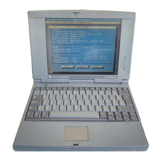
Section 1 General Description Introduction This manual contains field and factory level servicing information for the Texas Instruments Extensa 450 Series of Notebook Computers (Figure 1-1). This section provides a general overview and specifications for the Extensa 450 Series Notebook Computers. Figure1-1 Extensa 450 Series Notebook Computer General Description 1-1... -
Page 10: Product Models
Product Models Table 1-1 summarizes the features of the product models initially available in the Extensa 450 product line. Basically, the product models offer a choice of either 10.4" Dual Scan Color or 9.4" Active Matrix Color LCDs and a choice of either the basic Windows 95 operating system or Windows 95 plus applications. -
Page 11: Product Overview
Product Overview All members of the Extensa 450 Series are high performance notebooks powered by the 75MHz IntelDX4 processor and Windows 95 Operating System software. As a standard feature, all members of the Extensa 450 family also contain the following features: 4MB of RAM memory (user-expandable to 32MB) 128 bytes of battery-backed up CMOS RAM 512 KB of video RAM... - Page 12 Figure 1-2 Extensa 450 Series Features General Description...
-
Page 13: External Ports
1.4.1 External Ports As shown in Figure 1-3, the notebook computer contains the following external ports: Serial Infrared (SIR) Port for wireless connection with a similarly equipped printer or computer 9-Pin Serial Port for attaching any RS-232 type serial device to the Notebook 15-Pin External VGA Monitor Port for attaching an external monitor 6-Pin PS/2 Port to attach an external Keyboard or Mouse Second 6-Pin PS/2 Port for attaching an external Keyboard/Mouse... -
Page 14: Touchpad Pointing Device
1.4.2 Touchpad Pointing Device All members of the Extensa family feature a built-in Touchpad pointing device located near the center of the keyboard’s palmrest. With light presure, the cursor can quickly be positioned to the desired point; a quick double tap on the Touchpad and you have selected an object. - Page 15 The notebook keyboard is available in the following versions: U.S. English - This version (also known as the domestic version) has 81 keys and is generally used in the United States and Canada. U.K. English - This version (also known as the international version) has 82 keys and is generally used in England, Germany, and other European countries with the appropriate keycap changes.
-
Page 16: Standard Power Features
the Fn key with the appropriate keys provides cursor movement, paging and other functions in the normal mode. Scroll Lock indicator. This LED lights to indicate that the keyboard is locked in the scroll mode. Hard Disk Drive Activity Indicator. Indicates when notebook is accessing the hard drive. -
Page 17: Wireless Connection With Serial Infrared Port
All members of the Extensa 450 family feature TI’s patented power management subsystem (hardware and software) that provides longer portable operation and protection of files during low battery conditions. 1.4.5 Wireless Connection With Serial Infrared Port The Extensa series notebooks are equipped with a Serial Infrared (IR) port that offers wireless communication with a variety of IRDA-compliant devices made by other manufacturers. -
Page 18: Standard Test Features
Third Party External PS/2 keyboard (or external mouse) Standard Test Features The Extensa Series Notebook Computers use modular design and built-in test features to reduce the mean time to repair. A power on self-test automatically verifies the operational state of the primary circuits and a powerful suite of diagnostic tests are available to further test selected parts of the system. -
Page 19: Cover-Display Assembly
1.6.1 Cover-Display Assembly The Cover-Display Assembly contains the LCD screen and associated high voltage power supply and video circuitry. The Cover-Display Assembly contains three field-replaceable components including: LCD Assembly Inverter Board Slide Pot/Converter Board The Cover-Display Assembly attaches to the System Base Assembly through four top mounted screws and six mounting screws on the bottom of the computer. -
Page 20: Extensa 450 Series Notebook Specifications
Extensa 450 Series Notebook Specifications Specifications for the Extensa 450 Series Notebooks are provided in Table 1-6. Table 1-6 Extensa 450 Notebook Features Specifications Models 450/450T Models 455/455T Memory: Standard: Maximum 32MB 32MB Display LCD Type: 10.4" Dual Scan Color 9.4"... -
Page 21: Agency Approvals
Specifications Models 450/450T Models 455/455T Software Windows 95 Windows 95,plus applications Physical Characteristics Weight: Approx. 5.0 Pounds Approx. 5.0 Pounds (2.27kg) * (2.27kg) Dimensions: 11.7” (L) X 1.7” (H) X 11.7” (L) X 1.7” (H) X 8.2” (W) 8.2” (W) * Wight specifications do not include Floppy Drive, AC Adapter or... -
Page 22: Installation
Installation Introduction This section contains unpacking and preparation for use instructions for the Extensa 450 Series Notebook Computers. Unpacking Instructions The packaging diagram for the notebook computer is shown in Figure 2-1. Unpack the computer using the following instructions: 1. Carefully cut the tape that seals the top flap of the shipping carton. 2. - Page 23 Ensure that the notebook is powered off and that the AC Adapter and internal battery pack(s) is (are) removed from the notebook. Remove the DIMM module(s) from its shipping container. Release the Keyboard by pulling the keyboard release tabs forward (tabs are located underneath the Ctrl and right arrow keys).
-
Page 24: Installing Pcmcia Options
2.3.2 Installing PCMCIA Options The Notebook has provisions for one Type I or Type II PCMCIA option card. However, a type III PCMCIA device can be installed if the Floppy Drive is removed from the notebook and the optional PCMCIA Module is installed.. Review the installation instructions supplied with the PCMCIA option card(s). -
Page 25: Installing The Port Adapter
2.3.3 Installing the Port Adapter Note: Skip this paragraph if not installing the Port Adapter at this time. To install the Port Adapter, refer to Figure 2-3 and use the following procedure: Remove the -port adapter and any accessories from its shipping carton . Disconnect the AC Adapter from the notebook (if attached). -
Page 26: Installing The Optional Numeric Keypad
2.3.4 Installing the Optional Numeric Keypad An optional numeric keyboard can be attached to the notebook via the notebook’s PS/2 connector as shown in Figure 2-4. Figure 2-4 Installing the Numeric Keypad option Installing the Battery Pack(s ) The standard configuration of the Extensa Notebook is equipped with a single battery pack that is inserted from the front right side of the computer. -
Page 27: Installing External Devices
Caution: There is danger of explosion if the battery is incorrectly re- placed. Replace the battery only with the same or an equivalent type recommended by the manufacturer. Discard used batteries according to the manufacturer’s instructions. Installing External Devices Most external devices connect to the Notebook via the connectors on the rear of the notebook and on the rear of the Port Adapter supplied with the notebook (see Figure 2-5 for port assignments). - Page 28 PS/2 Ports Figure 2-6 PS/2 Port Assignments/Pinouts To install an external keyboard or external PS/2 mouse on the notebook, use the following procedure: Ensure that the notebook is powered off. Locate the external PS/2 ports at the rear of the notebook (see Figure 2-6). Attach the PS/2 cable from your mouse and/or keyboard cable to the PS/2 port(s).
-
Page 29: Installing External Parallel Printer
2.5.2 Installing External Parallel Printer The Notebook is equipped with a bi-directional, ECC/EPP compatible, 25-pin parallel printer port. The connector pinouts and connector location are shown in Figure 2-7. If you will be using a parallel interface, connect the 25-pin male connector of your printer cable to the 25-pin female parallel port on your notebook. - Page 30 Caution: Never connect a parallel device to a serial port or a serial de- vice to a parallel port or video port; this may cause damage to the Note- book and/or peripheral device. If you are uncertain of what type connector the external device has, refer to the technical manual for the external device.
-
Page 31: Installing External Vga Monitor
2.5.4 Installing External VGA Monitor The notebook is capable of driving both its internal LCD display and an external VGA monitor (LCD only, simultaneous, or VGA only). The external monitor connector pinouts and connector locations are shown in Figure 2-9. To install an external monitor with the notebook, use the following steps: Ensure that both the notebook and the external monitor are turned off. -
Page 32: Installing The Ac Power Adapter
Figure 2-9 External Monitor Port Pinouts Installing the AC Power Adapter Use the following procedures to connect the AC Adapter to the system: Caution: Use only the AC Adapter supplied with the computer; other adapters can damage the unit. Remove the AC adapter from the packaging. Connect the round coaxial connector supplied with the notebook to the power receptacle on the rear of the notebook as shown in Figure 2-10. -
Page 33: Initial System Checkout
Figure 2-10 AC Adapter Installation Initial System Checkout After you’ve installed all internal options and external cabling, you’re ready for system checkout and software configuration. To check out the system, set the power switch on the notebook to the On (I) position which initiates the notebook self test. -
Page 34: Making Backups Of System Software
Making Backups of System Software The Notebook is preloaded with Windows 95 operating system software. Prior to extended use of the notebook, create a backup set of system software using the Backup Utility under Windows 95. In the event of a disk problem, you can restore your system using the Restore Utility and the set of backup diskettes you’ve just created. -
Page 35: Section 3 Operating Instructions
Operating Instructions Introduction The first two subsections describe the Extensa 450 Series Notebook operating controls and indicators. The remainder of this section contains a summary of computer operations related to notebook maintenance including how to restore system software. Note: For additional operating instructions, see Extensa 450 Series Notebook Com- puter Users Guide, TI Part No.9803942-0001. -
Page 36: Button Switches
Figure 3-1 Extensa Series Controls and Indicators 3.2.1 LCD Contrast Control The TFT version of the notebook contains no operating controls or indicators. The Dual Scan version of the display contains a contrast switch on the lower right side as shown in Figure 3-1. 3.2.2 Button Switches The notebook contains two button switches above the keyboard including:... -
Page 37: Cover Release Latch
3.2.3 Cover Release Latch The Notebook contains one Cover Release latch . To open the notebook, slide the Release Mechanism to the right and lift up on the front edge of the notebook cover. 3.2.4 Touch Pad Controls The Extensa 450 Series Notebook Computers are equipped with a built-in mouse device called “the Touchpad”... -
Page 38: Installing/Removing Pcmcia Options
Never turn off or reset the notebook while the floppy activity indicator is lit. Keep the AC adapter at least 6 inches away from your drive. Insert the floppy into the floppy drive slot with the label side up and the metal-shutter end first. -
Page 39: Responding To Low Battery Conditions
3.3.4 Responding to Low Battery Conditions The computer generally will notify you when you are reaching a low battery condition by the following: Four short beeps per minute (unless battery warning is disabled) The battery low warning is automatically disabled when the AC Adapter is installed on the notebook regardless of the charge condition of the battery pack. -
Page 40: Rebuilding The System Software
3.3.8 Rebuilding the System Software In the event of a hard drive replacement or system board replacement which resulted in loss of system software, you may need to rebuilt the entire system software structure. The following items are required to rebuild the system software: Set of backup diskettes of the system software Operational Notebook Insert the Windows 95 Startup Diskette in the Notebook’s floppy drive and power up... -
Page 41: Section 4 Theory Of Operation
Theory of Operation Introduction This section describes the notebook theory of operation. Notebook Functional Description Functionally, the notebook computer consists of the following major subsystems: Processor and Memory Subsystem I/O Subsystem Video Subsystem Hard Disk Subsystem Floppy Disk Subsystem PCMCIA Subsystem Serial Infrared Subsystem Power Subsystem A functional block diagram of the Extensa Notebook is shown in Figure 4-1. - Page 42 Figure 4-1 Notebook Functional Block Diagram Theory...
- Page 43 Table 4-1 Extensa Series I/O Address Map Address Range Device 000-00F DMA Controller 1 020-021 Interrupt Controller-1 022-023 M1429 Registers 040-043 Timer 1 060-06E Keyboard Controller 8742 Chip Select 070-071 Real Time Clock and NMI Mask 080-08F DMA Page Register 0A0-0A1 Interrupt Controller 2 0C0-0DF...
- Page 44 Table 4-2 DMA Channels Controller Channel Address Function 0087 Spare 0083 Spare 0081 Diskette 0082 Spare Cascade Cascade 008B Spare 0089 Spare 008A Spare Table 4-3 IRQ Interrupt Levels Priority Interrupt Interrupt Source Number Power management unit Parity Error Detected,,I/O Channel Error IRQ0 Interval Timer,,Counter 0 Output IRQ1...
-
Page 45: I/O Subsystem
Note: A PCMCIA card can use IRQ 3, 4, 5, 7, 9 and 11 as long as it does not conflict with the interrupt address of any other device. 4.2.2 I/O Subsystem The I/O subsystem, implemented with an NS87334 VJG Super I/O Controller Chip, provides for such functions as internal Hard Drive control, floppy drive control, serial and parallel ports and support for the Serial Infrared port. -
Page 46: Video Subsystem
Includes protection circuit against damage caused when printer is powered up, or operated at higher voltages Integral IDE controller Provides a complete IDE interface with DMA control (except for optional buffers) Integral address decoder- provides selection of all primary and secondary ISA addresses including COM1-4 and LPT1-3. -
Page 47: Hard Disk Subsystem
4.2.3.1 External VGA Drive Capability On the Extensa 450, the external VGA port is provided by the port adaptor fixture in the form of a 15-pin, female, D-type connector which can be used to drive an external CRT (standard VGA modes with resolutions of 800 X 600 X 256, or 640 X 480 X 256 ). -
Page 48: Power Subsystem
Direct connection to ISA (PC AT) Bus Direct connection to PCMCIA 2.0 Bus PCMCIA 2.0- and JEIDA 4.1-compliant 82365SL-compatible register set, ExCA-compatible Automatic Low-power Dynamic Mode for lowest power consumption Programmable Suspend Mode Five programmable memory windows per socket Two I/O windows per socket Programmable card access cycle timing 8- or 16-bit CPU interface 8- or 16-bit PCMCIA interface support... -
Page 49: Primary Battery Pack
LCD standby mode Hard disk standby mode System standby/suspend mode Battery-low warning Standby/suspend upon battery low 4.2.7.2 AC Adapter The notebook uses an AC adapter with built in over voltage and short circuit protection. The adapter can with stand a continuous short-circuit to DC output without damage to the notebook logic components. -
Page 50: Secondary Battery Pack
4.2.7.4 Secondary Battery Pack As an optional feature, the Floppy Drive can be removed from the notebook and a Li-Ion (Lithium Ion) secondary battery pack can be installed in the same cavity to provide additional battery operating time. 4-10 Theory... -
Page 51: Section 5 Troubleshooting Procedures
Troubleshooting Procedures General This section provides the following information: Overview of the fault isolation process Guidelines for isolating computer malfunctions to replaceable subassemblies Instructions for executing diagnostics and interpreting error messages. Overview of Fault Isolation Process The fault isolation process (summarized in Figure 5-1) consists of the following: Quick Check of the following: Notebook power system (including battery packs and AC Adapter connections)- See Paragraph 5.4. -
Page 52: Troubleshooting
START COMPUTER TROUBLE INDICATION WHEN POWER SWITCH DEAD SET TO ON,, NO COMPUTER PARAGRAPHS INDICATION OF POWER; SYMTOMS 5.3.1 & 5.3.2 SCREEN DARK, STATUS LED's EXTINGUISHED SET POWER SWITCH TO ON. SELFTEST SELF TEST AUTOMATICALLY RUNS ERROR SEE PARAGRAPH MESSAGE 5.3.4 MODEM SEE PARAGRAPH... -
Page 53: Troubleshooting Procedures
Try rebooting the system (CTRL-ALT-DEL); restore system from diskettes, if necessary. If the computer is capable of running the Setup program; check the serial and parallel port configurations, and other features that may affect system operation. Run Diagnostics to further isolate problem area (See Paragraph 5.3.5). For indicated hardware failures, cycle power and repeat self test to verify that a hard failure has occurred. -
Page 54: Troubleshooting A Display Problem
Figure5-2 Troubleshooting Block Diagram If the AC outlet voltage, AC Adapter, and battery packs test normal but the computer will not power up, replace the Power Supply Board and/or Battery Board as described in Section 6. 5.3.2 Troubleshooting a Display Problem If the LCD remains blank when you turn on the computer, and the status indicators light, check the following controls on the display (See Figure 3-1): 5-4 Troubleshooting... -
Page 55: Fault Isolation Using Selftest
LCD standby mode - If the LCD backlight remains off, even with the Contrast Control set to its highest position, the LCD may be in Standby Mode. Press the Standby or Power button to power up the system. Notebook Set for External Monitor- use CMOS Setup to reset notebook. LCD - Replace the cover-display assembly as described in Section 6 of this manual. -
Page 56: Fault Isolation Using Diagnostics
5.3.5 Fault Isolation Using Diagnostics PC-Doctor supplied with the Extensa 450 Series Notebooks is a powerful diagnostics tool that can help you scan an internal RAM system for viruses, determine the hardware configuration of a local or remote system, benchmark its performance, analyze the performance of all subsystems, and perform a suite of interactive and non-interactive tests on attached devices. - Page 57 devices from your notebook and installing loopback plugs. The Non-Interactive test categories include: CPU and Co-Processor Tests Base RAM memory test System Board test Video Test Com1 and LPT1 serial port tests Parallel Port Test Fixed Disk test Diskette Drive tests Other devices (Sound card, PCMCIA options, etc.) Interactive Tests The PC-Doctor diagnostic test includes a suite of seven Interactive tests that require...
- Page 58 Supporting Online documentation The PC-Doctor Diagnostic contains the following online information sources: Online Technical Manual- selected at any time by pressing F1 key twice or by clicking on the Question Mark in the upper left hand corner of any PC-Doctor Menu On-line Help system that provides context sensitive information from every PC-Doctor screen- accessed by pressing F1 key once (pressing F1 twice gets...
- Page 59 Where the value 1440 is the capacity of the diskette (1.44 MB in this example). Get into the PC-Doctor directory ( type CD C:\PCDR and press Enter) Copy the PC-Doctor files to the bootable diskette using the following command: XCOPY C:. A:. After completion of this procedure, you should have a bootable diskette containing PC-Doctor.
-
Page 60: Section 6 Field Service
Field Service Introduction This section contains preventive and corrective maintenance procedures for the Extensa 450 Series Notebook Computers. The first part of the section describes the computer cleaning procedures and preferred handling procedures for sensitive components (e.g. disk drives, batteries). The second part of the section identifies all field replaceable parts;... -
Page 61: Protecting The Disk Drives
6.2.2 Protecting the Disk Drives To protect the disk drives and data, back up the system disk periodically on floppy diskettes. Periodically use a head-cleaning diskette in the floppy diskette drive to prolong the life of the drive and to help maintain data integrity. 6.2.3 Handling the Computer Battery Pack The battery pack furnished with the computer requires reasonable care and... -
Page 62: Notebook Field-Replaceable Parts And Assemblies
Caution: All boards, options and peripherals contain components that are sensitive to static electricity. When handling any of these items, pro- tect against static electricity by using wrist or ankle grounding straps and grounded working mats. When moving or storing items, use the anti- static bags supplied with the items. -
Page 63: System Base Assembly
Table 6-1 Cover Display Assembly, Field Replaceable Units (FRUs) FRU Description Reference FRU Description Reference Paragraph Paragraph Inverter Board, DSSTN 6.5.9 LCD Cover, DSSTN 6.5.9 10.4" 10.4", 450 Inverter Board, TFT 9.4" 6.5.9 LCD Cover, TFT 9.4", 6.5.9 450T Display Assembly, 10.4" 6.5.8 Bezel, DSSTN 10.4", 6.5.9... - Page 64 Table 6-2 Base Assembly, Field Replaceable Units (FRUs) FRU Description Reference FRU Description Reference Paragraph Paragraph Main Board Assembly 6.5.16 Touch Pad Assembly 6.5.11 Memory Board Assembly 6.5.15 Heat Sink Assembly 6.5.6 Serial IR Board Assembly 6.5.12 HDD Cable 6.5.4 Primary Battery Board 6.5.13 FDD Cable...
-
Page 65: Removing/Replacing The Notebook Battery Pack
Notebook Subassembly Removal and Replacement Procedures The following paragraphs contain field service-level removal/replacement procedures for the Notebook. Caution: Prior to removing any of the internal FRUs in the notebook, re- move the AC Adapter, battery, floppy and hard drives and all external op- tions installed on the notebook. -
Page 66: Removing/Replacing Pcmcia Options
6.5.2 Removing/Replacing PCMCIA Options The procedure for removing and replacing the PCMCIA options is as follows: Turn off the computer. Remove the PCMCIA device(s). To replace the PCMCIA Device, open the cover door and insert the device. Reinstall any external cabling required for the device. 6.5.3 Removing/Replacing the Floppy Drive To remove and replace the Floppy Drive, perform the following procedure:... -
Page 67: Removing/Replacing The Keyboard Assembly
Turn the computer over so that the Hard Drive panel is on your right side (See Figure 6-3). Press down on the circular bump with your thumb to release the hard drive cover; remove the cover and lay aside for later reinstallation. Using finger pressure, slide the metal cover downwards toward the edge of the notebook;... - Page 68 6.5.7 Removing/Replacing Dual Inline Memory Modules (DIMMS) To remove and replace the expansion memory, use the following procedure: Loosen the keyboard assembly (but do not disconnect keyboard cables) as described in steps 1 through 5 of Paragraph 6.5.5). Remove the Heatsink as described in Paragraph 6.5.6. Using the back edge of the keyboard as a hinge, lift the front edge of the keyboard up and lay it against the LCD assembly.
-
Page 69: Removing And Replacing The Cover-Display Assembly
6.5.8 Removing and Replacing the Cover-Display Assembly To remove the cover-display assembly, perform the following procedure: Remove the keyboard and heatsink as described in paragraphs 6.5.5 and 6.5.6 respectively. Remove the cable cover below the display by lifting upwards on the front edge of the cover. -
Page 70: Opening/Replacing The Top Case Assembly
Reinstallation of the Inverter Board is the reverse of steps 1 through 7 above. 6.5.10 Opening/Replacing the Top Case Assembly To remove/replace the Top Case Assembly, perform the following procedure: Remove the Keyboard Assembly and Heat Sink Assembly as described in Paragraphs 5.5.5 and 5.5.6. - Page 71 Figure 6-5 Touchpad Removal/Replacement 6-12 Field Service...
-
Page 72: Removing/Replacing The Sir Board
6.5.12 Removing/Replacing the SIR Board To remove and replace the SIR Board, perform the following procedure: Remove the Top Case Assembly as described in paragraph 6.5.10. Unplug the SIR Board cable connector from the Main Board (small leftmost cable connector at J8 as shown in Figure 6-6). Remove the SIR Board from the notebook. -
Page 73: Removing/Replacing The Primary Battery Board
6.5.13 Removing/Replacing the Primary Battery Board To remove and replace the Primary Battery Board, perform the following procedure: Remove the Top Case Assembly as described in paragraph 6.5.10. Disconnect the cable located next to the HDD Connector. Remove the two screws that secure the board to the plastics and remove the board. -
Page 74: Removing/Replacing The Memory Board
6.5.14 Removing/Replacing the Power Supply Board Assembly To remove and replace the Power Supply Board Assembly, perform the following procedure: Remove the Top Case Assembly as described in paragraph 6.5.10. Remove the metal shield that covers the Power Supply Board. Using a plastic stick, lift up on the end of the board that is adjacent to the processor. -
Page 75: Removing/Replacing The Main Board
Remove the Top Case Assembly as described in Paragraph 6.5.10. Using a plastic stick, lift up on the left and right edges of the board. The board assembly snaps out. Lift the board out of the unit. Reassembly is the reverse of steps 1 through 3 above. Figure 6-9 Memory Board Removal 6.5.16 Removing/Replacing the Main Board... -
Page 76: Removing/Replacing The Secondary Battery Board
Phillips-head screws as they are part of the PCMCIA connector hardware. Using a 5 mm hex driver, remove the hex nut adjacent to the display cable connectors. Lift up along the front edge of the Main Board Assembly until it clears the hard drive cavity;... - Page 77 Remove the Main Board Assembly as described in paragraph 6.5.16. Carefully slide the secondary Battery Board Assembly from its right angle connector and remove board from unit. Replacement is the reverse of steps 1 and 2 above. Figure 6-11 Secondary Battery Board 6-18 Field Service...
-
Page 78: Appendix A Self-Test Error Messages
Appendix A Self-Test Error Messages Introduction This appendix contains reference data useful in diagnosing and correcting self test errors. Table A-1 Self-Test Error Messages Error Message Corrective Action CMOS Battery Bad Replace Main Board CMOS Checksum Error Cycle power to Notebook; if problem persists Disk Boot Failure Insert a system disk in drive A... - Page 79 Error Message Corrective Action Keyboard Interface Error Cycle Power to Notebook. If problem persists Memory Size Mismatch Enter and then exit the System Configuration Setup in the Setup utility. Missing operating system Correct the HDD type and reboot. Refer to the specification label pasted on the back side of the notebook or attached to hard disk drive.
- Page 80 Checkpoint Description Normal POST start DMA page register write/read test in-progress or fail RAM refresh verification in-progress or failure 1st 64K RAM test in-progress 1st 64K RAM chip or data line failure - multi-bit 1st 64K RAM odd/even logic failure 1st 64K RAM address line failure 1st 64K RAM parity test in_progress or failure 1st 64K RAM chip or data line failure bit 0...
- Page 81 Checkpoint Description Normal POST start Interval timer channel 2 test in_progress or failure Time-Of-Day clock test in_progress or failure Serial port test test in_progress or failure Parallel port test test in_progress or failure Math Coprocessor test in_progress or failure Initial M1429 Dynamic Memory Configuration &...
- Page 82 Checkpoint Description Normal POST start Begin to configures PCI VGA devices Allocate Space for option ROM Error Messages A-5...
-
Page 83: Appendix B Connector Pinouts
Appendix B Connector Pinouts Introduction This appendix contains connector pinout data for the Extensa 450 Series Notebook Computers. Table B-1 PS/2 Mouse/Keyboard Port (J2) Pin Assignments Pin Name Pin Name DATA XDATA CLOCK XCLOCK Table B-2 Parallel Port (J3) Pin Assignments Pin Name Pin Name -Strobe... - Page 84 Table B-3 LCD VR Board Connector Pin Assignments Pin Name Pin Name DCBATIN CCFT_ON CCFTID FPVEE LCDVEE Table B-4 SIR Connector (J8) Pin Assignments Pin Name Main Pin Name Board Board Pin No Pin No SIR Input N.C. DSR2# SIR Output SIR_RXD DTR2# SIR Input...
- Page 85 Table B-5 LCD Signal Connector (J12) Pin Assignments Pin Name Pin Name N.C. PLD16 LCD+5 PLC17 N.C. PLD18 PMOD PLD19 PSLD3 PLFS PSLD2 PSLD1 PSHFCLK PSLD0 DISPLAY PSUD7 LCD+5 PSUD6 PSUD5 LCDVEE PSUD4 PUD0 PUD1 PUD2 PUD3 PLD23 PLD0 PLC22 PLD1 PLD21 PLD2...
- Page 86 Table B- 6 FDD Connector (J11) Pin Assignments Pin Name Pin Name INDEX# WDATA# DR0# WGATE# TRK0# DSKCHG WRTPRT# MTR0# FDIR RDATA# 3_MODE INTFDD# STEP# HESEL Table B- 7 PCMCIA Connector (J21) Pin Assignments PC Card Interface ATA Interface Function Function B_IOWR# B_IOWR#...
- Page 87 PC Card Interface ATA Interface Function Function B_INPACK# B_REG#, B_SPKR# B_LED B_STSCHG# B_PDIAG B_D8 B_D8 B_D9 B_D9 B_D10 B_D10 B_CD2# B_CD2# PCMCIA#, GND, GND, B_D3 B_D3 B_CD1# B_CD1# B_D4 B_D4 B_D11 B_D11 B_D5 B_D5 B_D12 B_D12 B_D6 B_D6 B_D13 B_D13 B_D7 B_D7 B_D14...
- Page 88 PC Card Interface ATA Interface Function Function B_A8 N.C. B_A13 N.C. B_A14 N.C. B_WE# N.C. B_IREQ# B_IREQ B_VCC B_VCC B_VPP1 N.C. B_A16 N.C. B_A15 N.C. B_A12 N.C. B_A7 N.C. B_A6 N.C. B_A5 N.C. B_A4 N.C. B_A3 N.C. B_A2 B_A2 B_A1 B_A1 B_A0 B_A0...
- Page 89 Table B-8 Memory Board Connector Pin Assignments (J13) Main Main Board Main Memory Memory Board Pin Name Board I/O Board Board Pin Pin No Pin No. Name BRAS3# Output BRAS3# BRAS2# Output BRAS2# BMA10 Output BMA10 BMA9 Output BMA9 BMA4 Output BMA4 BMA1...
- Page 90 Main Main Board Main Memory Memory Board Pin Name Board I/O Board Board Pin Pin No Pin No. Name BHD29 BHD29 BHD28 BHD28 BHD27 BHD27 BHD26 BHD26 BHD25 BHD25 BHD24 BHD24 BHD23 BHD23 BHD22 BHD22 BHD21 BHD21 BHD20 BHD20 BHD19 BHD19 BHD18 BHD18...
- Page 91 Table B-9 Memory Board Connector Pin Assignments (J10) Main Main Board Main Board Memory Memory Board Pin Pin Name Board Board Pin Pin No. Name KMCLK Output KMCLK KMDATA KMDATA KBDATA KBDATA KBCLK Output KBCLK IRQ1 Input IRQ1 IRQ12 Input IRQ12 RST0# Output...
- Page 92 Main Main Board Main Board Memory Memory Board Pin Pin Name Board Board Pin Pin No. Name Output HDD_LED# Output HDD_LED# SLPLED Output SLPLED M/K# Output M/K# Output VCCSB Output VCCSB SYSREST Output SYSREST BT2_QCHG Output BT2_QCHG BT1_QCHG Output BT1_QCHG Output LED# Output...
- Page 93 Connector Pinouts B-11...
-
Page 94: Pc-Doctor Diagnostics
PC-Doctor Diagnostics Introduction The Extensa Series Notebooks are shipped with PC-Doctor, a powerful diagnostics tool that can help you determine the hardware configuration of a local or remote system, benchmark its performance, analyze the performance of all subsystems, and perform a suite of interactive and non-interactive tests on attached devices (such as printers, joystick devices, VGA monitors, SCSI devices, CD-ROM drives). -
Page 95: C.3 Keyboard Navigation
C.3 Keyboard Navigation The keys shown in Table C-1 can be used to navigate through the PC-Doctor menus: Table C-1 PC-Doctor Key Assignments Description Cursor Keys Moves the highlighted pointer. ENTER Selects the highlighted option. Cancels current function and goes back one step. -
Page 96: Pc-Doctor Menus
PC-Doctor Menus There are several selections available from the menu bar of the PC-Doctor Diagnostics main menu. These include: Diagnostics Interactive Tests Hardware Info Utility Quit C.5.1 Online Help (?) To obtain context sensitive help from any menu, press F1. Pressing F1 twice (or clicking on the question mark in the upper left-hand corner of the menu) provides you with complete online documentation. -
Page 97: Interactive Tests Menu
Pass Count - selects how many times tests are repeated. The highest limit is 9999 times. Test Logging - opens the Log Options menu that lets you define how test results are printed or stored to a file during testing. By default, PC-Doctor produces a test result file at the end of testing if an error was detected. -
Page 98: Hardware Info Menu
C.5.4 Hardware Info Menu This menu contains functions that determine and report on the setup of the computer. None of these functions perform diagnostic tests; however any errors are included in the reports. The following functions are available from the Hardware Info menu: System Configuration - lists main system configuration data. -
Page 99: C.6 Quitting Pc-Doctor
Memory Debugger - displays memory contents in either hexadecimal, decimal, or ASCII form Remote Operation - enables remote control if available Tech Support Form - allows you to collect information about the current system Battery Rundown - quickly deep-discharges the NiMh battery of a laptop computer. - Page 100 Printed in U.S.A.
Need help?
Do you have a question about the Extensa 450 Series and is the answer not in the manual?
Questions and answers