Table of Contents
Advertisement
Quick Links
Trace Oxygen Analyzer
OPERATING INSTRUCTIONS FOR
MODEL OT-3
MODEL OT-3
Trace Oxygen Analyzer
Toxic gases and or flammable liquids may be present in this monitoring system.
Personal protective equipment may be required when servicing this instrument.
Hazardous voltages exist on certain components internally which may persist
for a time even after the power is turned off and disconnected.
Only authorized personnel should conduct maintenance and/or servicing.
Before conducting any maintenance or servicing, consult with authorized
supervisor/manager.
Teledyne Analytical Instruments
DANGER
P/N M74173
10/28/2001
ECO#
i
Advertisement
Table of Contents

Related Manuals for Teledyne OT-3


Summary of Contents for Teledyne OT-3
- Page 1 Hazardous voltages exist on certain components internally which may persist for a time even after the power is turned off and disconnected. Only authorized personnel should conduct maintenance and/or servicing. Before conducting any maintenance or servicing, consult with authorized supervisor/manager. Teledyne Analytical Instruments...
- Page 2 Any safeguards required such as locks, labels, or redundancy, must be provided by the user or specifically requested of Teledyne at the time the order is placed.
- Page 3 Commonly available options are listed below, with check boxes. Any that are incorporated in the instrument for which this manual is supplied are indicated by a check mark in the box. Instrument Serial Number: _______________________ Teledyne Analytical Instruments...
- Page 4 Failure to do so may compromise the safe operation of the equipment. CAUTION: Risk of Electrical Shock Note: Additional information in the form of notes are Symbol included which emphasize specific topics regarding the present discussion. Teledyne Analytical Instruments...
- Page 5 Since the use of this instrument is beyond the control of Teledyne, no responsibility by Teledyne, its affiliates, and agents for damage or injury from misuse or neglect of this equipment is implied or assumed.
-
Page 6: Table Of Contents
2.3.2 Signal Processing Installation ...................13 3.1 Unpacking the Analyzer 3.2 Location and Mounting 3.2.2 Installing the Micro-fuel Cell 3.3 Electrical Connections 3.3.1 Primary Input Power 3.3.2 Analog Outputs 3.3.3 Alarm Relays 3.3.4 Relay Ratings 3.3.5 Solid State Relay Output Teledyne Analytical Instruments... - Page 7 5.2.1 When to Replace a Sensor 5.2.2 Ordering and Handling of Spare Sensors 5.2.3 Removing the Micro-fuel Cell 5.2.4 Installing a Micro-fuel Cell 5.2.5 Cell Warranty Conditions Appendix ..................36 A.1 Specifications A.2 Spare Parts List A.3 Reference Drawing A.4 Miscellaneous Teledyne Analytical Instruments...
-
Page 8: List Of Figures
Figure 3-1: Electrical Connectors for AC Control Unit ....15 Figure 3-2: Contact ID for FAILSAFE Relay Operation ....166 Figure 3-3: Gas Connections............19 Figure 3-4: OT-3 Sample System ..........21 Figure 4-1: Front Panel Control and Indicators......23 Figure 5-1: AC Fuse Replacement ..........32 Teledyne Analytical Instruments viii... -
Page 9: Introduction
Introduction Introduction Overview The Teledyne Electronic Technologies Analytical Instruments (TET/AI) Model OT-3 is a microprocessor-based trace oxygen analyzer for real-time measurement of the parts per million of oxygen in inert gases, or in a wide variety of gas mixtures. It features simple operation, fast response, and a compact, rugged construction. -
Page 10: Front Panel Description
All controls are accessible from the front panel. See Figure 1-1. The front panel has seven push-button membrane switches, a digital meter, and an alarm indicator LED for operating the analyzer. These features are described briefly here and in greater detail in Chapter 4, Operation. Teledyne Analytical Instruments... -
Page 11: Figure 1-1: Front Panel
Down Arrow: Increment values of parameters downwards as they are displayed on the LED readout. Digital LED Readout: The digital display is a LED device that produces large, bright, 7-segment numbers that are legible in any lighting environment. It has two functions: Teledyne Analytical Instruments... -
Page 12: Rear Panel Description
Alarm 1, Alarm 2, and Power Failure Alarm connections. Sensor Connector: Internal Sampling System, Sensor Connector. RS-232 Port: Serial Digital Output of concentration and range signals. SSR POWER (AC POWER UNITS ONLY): +15 VDC power output for powering Solid State Relays. Teledyne Analytical Instruments... -
Page 13: Figure 1-2: Rear Panel (Ac Version)
Trace Oxygen Analyzer Introduction Figure 1-2: Rear Panel (AC Version) Figure 1-3: Rear Panel (DC Version) Teledyne Analytical Instruments... -
Page 14: Operational Theory
Micro-fuel Cell: In the battery, all reactants are stored within the cell, whereas in the Micro-fuel Cell, one of the reactants (oxygen) comes from outside the device as a constituent of the sample gas being analyzed. The Micro-fuel Cell is therefore a hybrid Teledyne Analytical Instruments... -
Page 15: Anatomy Of A Micro-Fuel Cell
The space between the active elements is filled by a structure saturated with electrolyte. Cathode and anode are wet by this common pool. They each have a conductor connecting them, through some Teledyne Analytical Instruments... -
Page 16: Electrochemical Reactions
The output of the fuel cell is limited by: (1) the amount of oxygen in the cell at the time and (2) the amount of stored anode material. In the absence of oxygen (or any gases capable of oxidizing lead), no current is generated. Teledyne Analytical Instruments... -
Page 17: The Effect Of Pressure
Self-Test.) As the cell reaches the end of its useful life, the slope seen in Figure 2-2 decreases. As this occurs, the span adjustments will become larger. Teledyne Analytical Instruments... -
Page 18: Electronics
Control Unit. The signal processing electronics including the sensor amplifier, microcontroller, analog to digital, and digital to analog converters are located on the Main PCB, which is mounted vertically, just behind the front panel of the Control Unit. Teledyne Analytical Instruments... -
Page 19: Signal Processing
The digital concentration signal along with input from the front panel buttons (KEYBOARD) is processed by the microcontroller, and appropriate output signals are directed to the display and alarm relays. Teledyne Analytical Instruments... - Page 20 The same digital information is also sent to a 12-bit digital to analog converter (DAC) that produces the 0-10 V dc analog concentration signal and the 0-10 VDC analog range ID output. A voltage to current converter (E–I CONV) produces the 4-20 mA DC analog concentration signal. Teledyne Analytical Instruments...
-
Page 21: Installation
As soon as you receive the instrument, carefully unpack and inspect the Unit, and any included accessories for damage. Immediately report any damage to the shipping agent. The analyzer is shipped with all the materials you need to install and prepare the system for operation. Teledyne Analytical Instruments... -
Page 22: Location And Mounting
Electrical Connections Figure 3-1 shows the Model 3300T/OT-3 rear panel of the control unit. (See Figure 1-3 for DC version). To gain access to the terminal blocks, the analyzer door screws must be loosened, and the door opened. Teledyne Analytical Instruments... -
Page 23: Primary Input Power
0 V at 0 percent oxygen to 10 V at full scale percent oxygen. (Full scale = 100% of programmed range.) 0–10 V Range ID: 3.33 V = Low Range, 6.66 V = High Range, 10 V = Air Cal Range. Teledyne Analytical Instruments... -
Page 24: Alarm Relays
Alarm 1 and Alarm 2 can both be configured as either HI or LO. A HI alarm will activate when concentration is above threshold, while a LO alarm will activate when concentration is below threshhold. Figure 3-2: Contact ID for FAILSAFE Relay Operation Teledyne Analytical Instruments... -
Page 25: Relay Ratings
10 A @ 10mV To safely use the alarm relays in a hazardous location, the characteristics of both the switched voltage and the components or load being operated must be known. The alarm relays must not be attached to Teledyne Analytical Instruments... -
Page 26: Solid State Relay Output
( ¼” on the drain). There are three separate gas connections to be made plus a liquid drain connection: Sample gas Span gas (recommended concentration of 80-90% of the primary range of interest, balance N —typically 8-9 ppm or 80-90 ppm O in N Teledyne Analytical Instruments... -
Page 27: Figure 3-3: Gas Connections
TIE IN ONE LINE AT A TIME. MAKE SURE THAT THE CORRECT GAS LINE IS MATED TO THE PROPER FITTING ON THE INSTRUMENT. For maximum performance, the system should be installed in a manner to minimize the sample line length. Teledyne Analytical Instruments... -
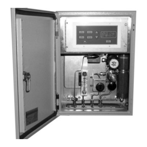
Page 28: Sample System
The clear housing permits a visual analysis regarding the condition of the scrubber medium and allows the user to predict service intervals. A switching valve is provided to feed the analysis unit with either sample or span gas. Teledyne Analytical Instruments... -
Page 29: Installation Checklist
Correctly installed the Sample and Exhaust gas lines Checked for leaks Set the flow Once the above checks have been made, you can connect to the power source. The instrument is now ready for operation. Teledyne Analytical Instruments... - Page 30 Installation OT-3 Teledyne Analytical Instruments...
-
Page 31: Operation
Analyzing for the trace oxygen level in the gas passing through the cell block is the default mode of operation. As long as no front panel buttons are being pressed the unit is analyzing. Figure 4-1: Front Panel Control and Indicators Teledyne Analytical Instruments... -
Page 32: Using The Function And Data Entry Buttons
LO range full-scale value, and it switches back to the LO range when the oxygen concentration falls below of the LO range full-scale value Note: The HI Range setpoint MUST be set at a higher concentration percentage than the LO Range setpoint. Teledyne Analytical Instruments... -
Page 33: Hi Range
3. To change the setting at which the alarm will be actuated, press the SET ALARM 1 function button once more. The alarm setpoint will flash on the LED display. Press either the Up or Down keys to raise or lower the displayed value, as required, Teledyne Analytical Instruments... -
Page 34: Set Alarm 2
Alarm Delay The alarms have a user-settable delay feature which can delay the onset of an alarm. The delay can be set from 0-20 minutes in 1 minute increments. Teledyne Analytical Instruments... -
Page 35: Keypad Lockout
Any number except 10 will lock the keypad. 3. After three seconds, the control unit will time-out and return to analyze mode. With the keypad locked, pressing the keys Teledyne Analytical Instruments... -
Page 36: Selecting A Fixed Range Or Autoranging
2. Move the gas selector valve to the SPAN position. 3. Adjust the pressure on the span gas to produce a 0.4-0.5 SCFH flow and allow the analyzer to stabilize before setting the span. 4. The analyzer reading should be stable prior to setting the span. Teledyne Analytical Instruments... -
Page 37: Displaying Percent & Ppm On The Led Display
CAUTION: TET/AI CONSIDERS THE ACTION OF PRESSING THE ALARM OR RANGE BUTTONS TO BE AT YOUR (THE USER’S) DISCRETION. BE AWARE THAT THE ALARMS WILL BECOME ACTIVE WITHIN 5 (FIVE) SECONDS IF THE RANGE Teledyne Analytical Instruments... - Page 38 Operation OT-3 OR ALARM BUTTONS ARE PRESSED DURING SPAN. THIS MAY RESULT IN FALSE ALARMS IF THE SPAN GAS HAS NOT BEEN FULLY PURGED FROM THE CELL AND SAMPLE LINES. Teledyne Analytical Instruments...
-
Page 39: Maintenance
4. Remove the bad fuse and replace it with a 5x20mm 0.5 A, 250 VAC, IEC time lag (T) fuse (P/N F1130). 5. Replace the fuse holder into its receptacle, pushing in firmly until it clicks. Teledyne Analytical Instruments... -
Page 40: Sensor Installation Or Replacement
Typically offsets of 1.0 ppm or less are acceptable. A cell failure may also be indicated by an inability to SPAN, or slow response to changes in O concentration at levels below 100 ppm. Teledyne Analytical Instruments... -
Page 41: Ordering And Handling Of Spare Sensors
EYES WITH WATER FOR AT LEAST 15 MINUTES. CALL A PHYSICIAN. (SEE APPENDIX, Material Safety Data Sheet—MSDS). 5.2.3 Removing the Micro-fuel Cell To remove a spent or damaged Micro-fuel Cell: 1. Disconnect the Power Source from the instrument. Teledyne Analytical Instruments... -
Page 42: Installing A Micro-Fuel Cell
6. Place the cell on the end of cell-retainer cap with the concentric gold rings facing up. 7. Careful insert the cap and cell into the block, and screw the cap clockwise into the cell block until it is fully closed. 8. Reconnect the electrical power. Teledyne Analytical Instruments... -
Page 43: Cell Warranty Conditions
If it is determined that failure is due to faulty workmanship or material, the cell will be replaced at no cost to you. Note: Evidence of damage due to tampering or mishandling will render the cell warranty null and void. Teledyne Analytical Instruments... -
Page 44: Appendix
System Power Requirement: AC (100-240 VAC, 50/60Hz @ 2.8W), or DC (10-36 VDC @2.8W ) Weight: 30.9Lbs (14 Kg) System Enclosure: NEMA 4 enclosure. 40 cm x 30 cm x 20.6 cm (15.8” x 11.8” x 8.1”) Teledyne Analytical Instruments... -
Page 45: Spare Parts List
IMPORTANT: Orders for replacement parts should include the part number and the model and serial number of the system for which the parts are intended. Send orders to: TELEDYNE ELECTRONIC TECHNOLOGIES Analytical Instruments 16830 Chestnut Street City of Industry, CA 91749-1580Telephone: (626) 934-1500 Fax: (626) 961-2538 or your local representative. -
Page 46: Reference Drawing
Schematic AC Power Supply PCB D-74161 Schematic DC Power Supply PCB B-74224 Wiring diagram 3300/OT-3 ext. SSR drive. A.4 Miscellaneous The symbol ~ is used on the rear panel of the Model OT-3 to signify volts alternating current (VAC). Teledyne Analytical Instruments... - Page 47 See reaction configuring the OT-3, 23 hazardous location, 17 contaminants, 8, 13, 20 HI Range, 25 control unit, 6 hydroxyl ion, 8 copyright, ii installation, 13 current generation, 11 installation checklist, 21 current output. See output Insta-Trace, 1 Teledyne Analytical Instruments...
- Page 48 15 stainless steel, 20 power connection, 4 stockpiling MFCs, 33 power cord, 15 switches power failure alarm. See alarm membrane, 2 power supply module, 10 temperature compensation, 2, 11 pressure, 21 temperature range, 2, 14 Teledyne Analytical Instruments...
- Page 49 37 universal power supply. See power website address, v supply module zero VAC symbol, 38 absolute, 9 vent, 19, 20 zero gas, 19, 32 voltage amplifier, 11 zero offset, 9, 32 voltage to current converter, 12 Teledyne Analytical Instruments...
- Page 50 Index OT-3 Teledyne Analytical Instruments...
Need help?
Do you have a question about the OT-3 and is the answer not in the manual?
Questions and answers