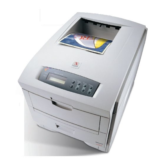
Xerox PHASER 1235 Service Quick Reference Manual
Network color printer
Hide thumbs
Also See for PHASER 1235:
- Brochure & specs (4 pages) ,
- Advanced features and troubleshooting manual (144 pages) ,
- Service manual (239 pages)
Advertisement
Quick Links
Download this manual
See also:
Service Manual
P H A S E R ® 1 2 3 5
N E T W O R K C O L O R P R I N T E R
S e rvic e Qu ic k R e f e re n c e G u i d e
Warning
The following servicing instructions are for
use by qualified service personnel only. To
avoid personal injury, do not perform any
servicing other than that contained in
operating instructions unless you are qualified
to do so.
This printing: December 2000
071-0728-00
Advertisement

Summary of Contents for Xerox PHASER 1235
- Page 1 P H A S E R ® 1 2 3 5 N E T W O R K C O L O R P R I N T E R S e rvic e Qu ic k R e f e re n c e G u i d e Warning The following servicing instructions are for use by qualified service personnel only.
- Page 2 Copyright © Xerox Corporation. Unpublished rights reserved under the copyright laws of the United States. Contents of this publication may not be reproduced in any form without permission of Xerox Corporation. ® ® ® ® ® Phaser , PhaserShare , ColorStix , the TekColor icon, Made For Each Other ®...
-
Page 3: Users Safety Summary
Users safety summary Terms in CAUTION Conditions that can result in damage to the product. manual: WARNING Conditions that can result in personal injury or loss of life. Power source: For 110 VAC printers, Do not apply more than 140 volts RMS between the supply conductors or between either supply conductor and ground. - Page 4 Symbols as marked on product: DANGER high voltage: Protective ground (earth) terminal: Use caution. Refer to the manual(s) for information: WARNING: If the product loses the ground connection, usage of knobs and controls (and other conductive parts) can cause an electrical shock. Electrical product may be hazardous if misused.
- Page 5 Contents General Information The Phaser 1235 Color Printer Printer RAM and printer capabilities CRU life counter behavior Print engine assemblies The image processor board The control panel On Line LED ! Fault Rear panel Accessing special operating modes System controller board LEDs Paper tray type sensing Specifications Regulatory specifications...
- Page 6 Jams Wrong media Paper jams at the paper tray Manual bypass feeder feed jams Paper jams at the registration rollers Paper jams at the transfer belt Fuser jams Eject jams Jams in the duplex unit No drum imaging unit installed Imaging drum unit up/down error Fan error Fuser unit error...
- Page 7 Service Tests and Adjustments Diagnostics mode Switch scan test LED head test Motor and clutch tests Test printing Consumable count initialization Consumable counter display Consumable continuation counter display Adjusting color density and balance Printing a Test Page Interpreting the Color Balance test print What to look for Making adjustments Adjustment recovery...
- Page 8 Left plate assembly Electronic boards System controller board Print engine controller board Toner sensor board Entrance sensor board High voltage power supply Low voltage power supply Control panel Paper feed components Tray 1 feed roller and nudger roller Retard pad Paper-size sensing board Paper-size sensing actuator Main feeder assembly...
- Page 9 Drive assembly components Main motor assembly Main feeder drive motor Transfer belt motor assembly Xerographic components Shutter plate Color registration sensor assembly Color registration solenoid LED assembly Drum contact assembly Toner sensor actuators Duplex unit Optional paper feeder components Idler roller assembly Inner frame Feeder clutch Feeder motor...
- Page 10 Figures The Phaser 1235 Color Printer with lower tray feeders 1 Print engine circuit boards 5 Print engine circuit boards (cont’d) 6 Print engine sensor and switch locations 7 Print engine sensor and switch locations (cont’d) 8 Print engine motors, clutches and solenoids 9 Optional feeder motor and clutch 10 Features of the controller board 11 The control panel 12...
- Page 11 Removing the entrance sensor board 113 Removing the high voltage power supply 115 Removing the low voltage power supply 116 Removing the control panel 117 Removing the feed roller and nudger roller 118 Removing the retard pad 119 Removing the paper size sensing board 121 Removing the paper size sensing actuator 122 Removing the main feeder assembly 124 Removing the lower plate assembly 125...
- Page 12 Removing the feeder control board cover 167 Removing the optional feeder inner plate 168 Removing the feeder control board cover 169 Removing the feeder clutch 170 Removing the feeder control board cover 171 Removing the feeder motor 172 Removing the feeder control board cover 173 Removing the feeder control board 174 Removing the feeder control board cover plate 175 Removing the paper transport roll guide 176...
- Page 13 Tables Entering special operating modes 14 Paper size detection 15 Physical dimensions 16 Printer clearances 16 Functional specifications 17 Electrical specifications 18 Environmental specifications 18 Printer fault messages 21 POWER Connector pinout 35 Motor and fuser roller resistances 38 Engine maintenance mode menu 62 Switch scans and the sensor and switches test 64 Motor and clutch test constraints 69 Test Print menu 71...


