Table of Contents
Advertisement
Quick Links
Operator's
Manual
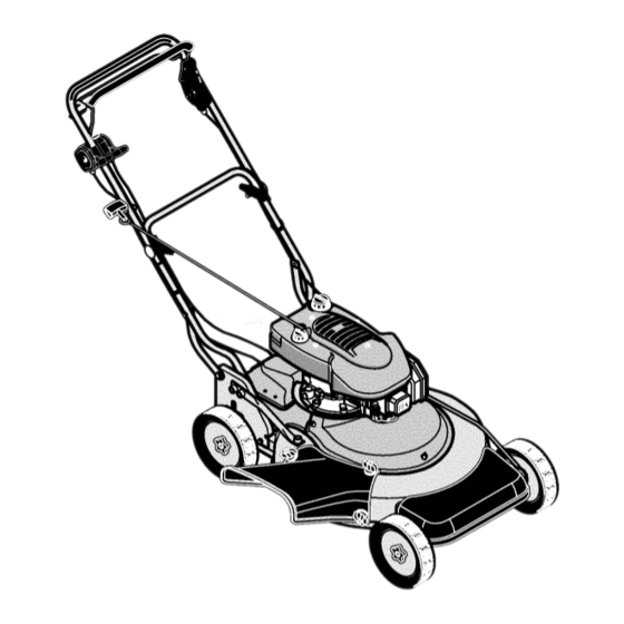
Rotary Lawn Mower
26-inch Wide Cut
Variable Speed
Rear Drive
Model 536.885601
• Safety
• Assembly
• Operation
• Maintenance
• Service And Adjustment
• Repair Parts
CAUTION:
Before using this
product, read this manual
and follow all of its Safety
Rules and Operating
Instructions.
/
Manual del usario
Cortacdsped
Ancho de corte de 26 pulg.
Velocidad variable
Traccibn trasera
Modelo 536.885601
PRECAUCION:
Antes de usar este
producto, lea este manual y siga
todas las reglas de seguridad
e
instrucciones
de operaci6n.
• Seguridad
• Ensamblaje
• Operacibn
• Mantenimiento
• Servicio y ajustes
• Piezas de repuesto
Sears, Roebuck and Co., Hoffman Estates, IL. 60179 U.S.A.
F-020433M
www.sears.com/craftsman
Advertisement
Table of Contents

Related Manuals for Craftsman 536.885601


Summary of Contents for Craftsman 536.885601
- Page 1 PRECAUCION: Antes de usar este • Mantenimiento producto, lea este manual y siga • Servicio y ajustes todas las reglas de seguridad • Piezas de repuesto instrucciones de operaci6n. Sears, Roebuck and Co., Hoffman Estates, IL. 60179 U.S.A. F-020433M www.sears.com/craftsman...
-
Page 2: Table Of Contents
PARTS For two (2) years from the date of purchase, if this Craftsman Equipment is maintained, lubricated and tuned up according to the instructions in the owner's manual, Sears will repair or replace free of charge any parts found to be defective in material or workmanship. - Page 3 Congratulations on your purchase of a Craftsman Rotary Lawn Mower. It has been designed, engineered and manufactured to Rotary Lawn Mower give you the best possible dependability and performance. Record in the space below the serial number and the date If you experience any problems you cannot easily remedy, please of purchase of this unit.
-
Page 4: Owner's Information
OWNER'S INFORMATION CUSTOMER RESPONSIBILITIES Environmental Awareness It is the owner's responsibility to follow the instructions be- low. Carefully read and follow the rules for safe operation. • Do not fill the engine's fuel tank completely full. Follow all the assembly instructions. •... - Page 5 OWNER'S INFORMATION Watch for holes, ruts, or bumps. Tall grass can hide obstacles. ning. Disconnect the spark plug wire, and keep the wire away from the plug to prevent accidental starting. Always wear eye DO NOT: protection when you make adjustments or repairs. Do not mow near drop-offs, ditches, or embankments.
-
Page 6: Preparation
PREPARATION UNPACKING INSTRUCTIONS Folded Position The mower was fully assembled at the factory. When the mower was put in the carton, the handle was put in a folded position (see Figure 1). To put the handle in the operating position, follow the steps below. -
Page 7: Important! Before You Start Mowing
PREPARATION HOW TO PREPARE THE ENGINE ENGINE DOES NOT CONTAIN OIL OR GASOLINE See "Before Starting The Engine" in the Operation section for the type of oil and gasoline to use. Before you use the unit, read the information on safety, operation, maintenance, and storage. IMPORTANT: This unit is equipped with an internal combustion engine and must not be used on or near any... -
Page 8: Operation
OPERATION Blade Rotation Control Drive Lever Blade Rotation Transmission" Speed Control Throttle Control Recoil-Start Grip Oil Fill Single Lever Gas Fill Height Adjuster Primer Button Mulch Cover Attachment Side Discharge Attachment Figure 4 KNOW YOUR PRODUCT BLADE ROTATION CONTROL: MULCH COVER ATTACHMENT: For the blade to ro- to mulch the tate, the blade rotation control must be in the ENGAGED position... -
Page 9: How To Use The Throttle Control
OPERATION HOW TO USE THE THROTTLE CONTROL Use the throttle control to increase or decrease the speed of the engine. To increase the engine speed, move the throttle control forward to the FAST position. For normal operation and when using a grass bagger, move the throttle control to the FAST position. -
Page 10: How To Operate The Rear Wheel Drive
OPERATION HOW TO OPERATE THE REAR WHEEL DRIVE IMPORTANT: When you operate, always operate with the NOTE: To stop the engine, move the throttle control lever to the throttle control in the FAST position. OFF position. WARNING: For safe operation, the drive system Height Of Cut is released. -
Page 11: Mulching Tips
OPERATION Remove the mulch cover. HOW TO INSTALL THE SIDE DISCHARGE ATTACHMENT Mount the side discharge attachment on the mower hous- ing (see Figure 10). ARNING: To prevent the engine from starting, dis- connect the wire from the spark plug. Make sure the side discharge attachment is mounted on all Remove the three wingnuts that secure the mulch cover to three bolts and fasten with the wingnuts... -
Page 12: Before Starting The Engine
OPERATION BEFORE STARTING THE ENGINE ADD GASOLINE WARNING: Always use a safety gasoline container. Do not smoke when adding gasoline to the fuel tank. Do not add gasoline when you are inside an ADD OIL enclosure. Before you add gasoline, stop the en- gine and let the engine cool for several minutes. -
Page 13: Maintenance
MAINTENANCE MAINTENANCE CHART FIRST EVERY EVERY EVERY EACH BEFORE PROCEDURE HOURS HOURS HOURS HOURS STORAGE Oil, Check Cooling System, Clean Air Filter, Clean / Change Spark Plug, Replace Dusty conditions every 25 hours. GENERAL RECOMMENDATIONS WARNING: Before you make an inspection, adjust- The owner's responsibility is to maintain this product. -
Page 14: How To Remove And Install The Blade
MAINTENANCE INSPECT BLADE 10. Tighten the nut that holds the blade to a torque of 35 foot pounds (47,5 N-m). WARNING: Before you inspect or remove the blade, disconnect the wire to the spark plug. If the blade hits an object, stop the engine. Check the unit for damage. -
Page 15: How To Check The Oil
MAINTENANCE ENGINE HOW TO CHECK THE OIL Fuel Cap Dipstick NOTE: Do not check the level of the oil while the engine runs, Make sure the unit is level. Clean the area around the dipstick (Figure 17). Remove the dipstick. Wipe the oil from the dipstick. Insert the dipstick into the oil fill tube. -
Page 16: How To Clean The Air Filters (Flat Type)
MAINTENANCE HOW TO CLEAN THE AIR FILTERS (FLAT TYPE) NOTE: Never run the engine with the air filters removed. The air filters will help protect the engine against wear. For the correct replacement filter, see the parts list for the engine. Loosen screw and tilt cover down (Figure 19). -
Page 17: Service And Adjustment
SERVICE AND ADJUSTMENT HOW TO ADJUST THE BLADE DRIVE SYSTEM ARNING: To prevent an injury, the blade rotation control must operate correctly. In normal usage, the blade drive system will not require an adjustment. However, if the cutting performance decreases or the Drive Control quality of cut is poor, make the following changes. -
Page 18: How To Replace The Belts
SERVICE AND ADJUSTMENT HOW TO REPLACE THE BELTS Put the blade drive belt onto the bottom pulley of the en- the wire from the spark plug. gine stack pulley. Make sure that the flat side of the blade ARNING: Before you remove a belt, disconnect drive belt is against the idler pulley. -
Page 19: How To Adjust The Drive Cable
SERVICE AND ADJUSTMENT HOW TO ADJUST THE DRIVE CABLE If the drive system does not engage and disengage correctly, check the handle for correct assembly. Make sure that all parts are in good condition, not broken or bent, and that all fasteners are tight. -
Page 20: Storage
STORAGE FOLDING HANDLE STORAGE CAUTION: Be careful when you fold or raise the handle. Do not damage the cables. A cable that is bent will not work cor- rectly. Before you use the unit, replace a bent or damaged cable. How To Fold The Handle Remove the adjuster arms from the lower handle (see Figure 26). -
Page 21: Troubleshooting Chart
TROUBLESHOOTING CHART Check the blade adapter. REPLACE A BROKEN BLADE PROBLEM: The engine will not start. ADAPTER. Follow the steps, "How To Start The Engine" in this book. Check for loose engine bolts. Electric-Start Models: Clean the battery terminals. Tighten the cables. -
Page 22: Slope Guide
Operate a walk-behind mower across the face of slopes, never up or down slopes. Operate a riding mower up or down slopes, never _ulJ,, across the face of slopes. 10 DEGREES 15 DEGREES On a riding mower to determine if a slope is safe to mow: (1) disengage the blade(s), (2) put the unit in reverse, and (3) try to back straight up the slope. - Page 23 (This page applicable in the U.S.A. and Canada only.) Briggs & Stratton Corporation (B&S), the California Air Resources Board (CARB) and the United States Environmental Protection Agency (U.S. EPA) Emission Control System Warranty Statement (Owner's Defect Warranty Rights and Obligations) EMISSION CONTROL WARRANTY COVERAGE IS APPLICABLE TO CERTIFIED ENGINES PURCHASED...
- Page 24 5. Maintenance Any Warranted Part w hich i snot s cheduled forreplacement asrequired maintenance orwhich i sscheduled only forregular inspec- tion tothe effect of"repair orreplace asnecessary" shall bewarranted astodefects forthe warranty period. Any Warranted Part which isscheduled forreplacement asrequired maintenance shall bewarranted astodefects only f orthe period o ftime uptothe first s ched- uled replacement for t hat p art.
- Page 25 GENERAL INFORMATION ENGINE MODEL This is a single cylinder, overhead valve (OHV), air-cooled engine. It is a low emissions engine. In the state of California, OHV Model Series 110000 and 120000 engines are certified by the California Air Resources Board to meet emissions standards for 125 hours. Such certification does not grant the purchaser, owner or operator of this engine any additional warranties with respect to the performance or operational life of this engine.
-
Page 26: Index
INDEX Gas Fill, 8 Height Adjuster, 8 Filter, Air, 16 Adjustments, Height Of Cut, 9 Blade Rotation Control, 17 Fuel, Type, 12 Location Of Controls, 8 Air Screen, 15 Mulch Cover Attachment, 8 Mulching, 11 Gas Fill, Location, 8 Oil Fill, 8 Primer Button, 8 Belt, Mower Drive, Adjust, 17 Rear Wheel Drive, 10... -
Page 27: Repair Parts
REPAIR PARTS CRAFTSMAN MODEL 536.885601 HANDLE ASSEMBLY Description Part No. Description Part No. Knob, Handle 1101453 1101188-848 Lever, Drive 1101217-846 Handle, Lower 1101160 Cover, Stop Lever Bolt, Handle Support lx183 Control, Blade 1101374 15x79 Nut, Flange Screw 3x 144 1101154... - Page 28 CRAFTSMAN MODEL 536.885601 REPAIR PARTS DRIVE ASSEMBLY 26 32 F-O20433M...
- Page 29 CRAFTSMAN MODEL 536.885601 REPAIR PARTS DRIVE ASSEMBLY Part No. Description Part No. Description Screw Engine lx111 26x305 Screw 56526 Pulley, Idler 28x75 Tinnerman, "U" 15x121 Nut, Blade Pulley 1101164 Cover, Front 1101191 Pulley, Blade 1101166 Cover, Transmission 18x31 Washer, Split...
- Page 30 CRAFTSMAN MODEL 536.885601 REPAIR PARTS FIXED WHEEL ASSEMBLY 15 ._'i /" F-O20433M...
- Page 31 710271 Screw 1101222 Knob 1101221-848 Housing, Mower 26x301 Screw 1101161 Deflector, Chute 1101223 Panel, Front 1101162 Cover, Mulch Part No. Description 48x912 Decal, Craftsman 48x913 Decal, 26" Cut 48x978 Decal, Cut Finger 48x902 Decal, Caution 48x962 Decal, Cut Height F-020433M...
- Page 32 MODEL 536.885601 B&S ENGINE 120602-0129-E1 34. J 1029_ '11026 •'k REQUIRES SPECIAL TOOLS TO INSTALL. SEE REPAIR 914 _' INSTRUCTION MANUAL. 102311022 615_ 505@ 1058 OWNER'S MANUAL I 1019 LABEL KIT I 24[_ F-O20433M...
- Page 33 MODEL 536.885601 B&S ENGINE 120602-0129-E1 REF. PART REF. PART REF. PART DESCRIPTION DESCRIPTION DESCRIPTION 692670 Cylinder Assembly 692786 Ring Set (Governor Control Lever 692937 Grommet 399269 Kit-Bushing/Seal (.020" Oversize) _299819 Seal-Oil 94852 Bolt 692787 Ring Set (Magneto Side) (.030" Oversize) (Governor Control Lever 691866 Lock-Piston...
- Page 34 MODEL 536.885601 B&S ENGINE 120602-0129-E1 633 @ 276 O 287_ 190_ I s23J 300J 613 "_ )842 613_ 883 _ "'-J_ F-O20433M...
- Page 35 MODEL 536.885601 B&S ENGINE 120602-0129-E1 REF. PART REF. PART REF. PART DESCRIPTION DESCRIPTION DESCRIPTION 51,,_.A692668 Gasket-Intake 693378 Bracket-Control 692669 Cover-Control 691636 Screw 691108 Screw 690798 Clamp-Casing 691044 Screw (Throttle Valve) (Muffler) 499682 Shaft-Throttle 613A 691140 Screw (Casing Clamp) °691242 Pin-Float Hinge 276 ,°271716 Washer-Sealing...
- Page 36 MODEL 536.885601 B&S ENGINE 120602-0129-E1 592 @ 58 459 _ 689 O 592 @ 305_ 1211 334 _ I 1036 LABEL-EMISSIONS F-O20433M...
- Page 37 MODEL 536.885601 B&S ENGINE 120602-0129-E1 REF. PART REF. PART REF. PART DESCRIPTION DESCRIPTION DESCRIPTION 690662 691696 Screw 692693 Flywheel 694086 Guard-Flywheel (Flywheel) (Pawl Friction Plate) 691421 Housing-Rewind Starter 802574 Armature-Magneto 691855 Spring-Friction 691061 Screw 692259 Rope-Starter 493880 TerminaI-Sparkplug 692675 Guard-Rewind (Cut to Required Length' (Magneto Armature) 1005...
- Page 38 MODEL 536.885601 B&S ENGINE 120602-0129-E1 358 ENGINE GASKET 58.. = 11__ s24_ 1095 VALVE GASKET 121 CARBURETOR OVERHAUL 104_ 127_ 7 _1022 276_ 137 O 977 CARBURETOR GASKET 633 O F-O20433M...
- Page 39 MODEL 536.885601 B&S ENGINE 120602-0129-E1 REF. PART REF. PART REF. PART DESCRIPTION DESCRIPTION DESCRIPTION _299819 Seal-Oil °694468 Plug-Welch _691031 SeaI-O Ring °398188 Kit-Needle/Seat (Magneto Side) (Dipstick Tube) 137 .°693981 Gasket-Float Bowl 868 _A692044 Seal-Valve 7 -kA695166 Gasket-Cylinder Head _272481 Gasket-Breather 163_.oA692667 Gasket-Air Cleaner...
-
Page 40: Espanol
El servicio de garantia est& disponible sin cargo si Ileva su equipo Craftsman al Centro de Servicio Sears mAs cercano a usted. Tambi6n tenemos disponible el servicio de garantia para reparaciones a domicilio pero se aplicar& a este servicio un cargo por el viaje. - Page 41 Felicidades por su compra de este cortac6sped de Craftsman. Su unidad ha sido diseSada y fabricada para darle los mejores Cortac_sped resultados en Io que se refiere a confiabilidad y desempeSo. Anote en los espacios correspondientes, el n6mero de serie Si encuentra alg6n problema dificultoso, consulte el y la fecha de compra de la unidad.
- Page 42 INFORMACION PARA EL PROPIETARIO RESPONSABILIDADES DEL PROPIETARIO Consideraciones ambientales Es la responsabilidad del propietario seguir las instruccio- nes enumeradas a continuacibn. Lea y siga las instrucciones detenidamente para el uso seguro • No Ilene completamente el tanque de combustible. del equipo. •...
- Page 43 INFORMACION PARA EL PROPIETARIO 19. Planee su patr6n de corte para evitar que la descarga del ma- b. Nunca retire la tapa del tanque de gasolina ni afiada combustible terial vaya hacia la calle, camino, acera, personas que se en- mientras el motor esta funcionando.
- Page 44 PREPARACION INSTRUCCIONES PARA DESEMBALAR Mango doblado Esta cortadora de c6sped fue completamente ensamblada en la f&brica. AI colocar la cortadora en la caja, el mango se pleg6 a la posici6n de almacenamiento (vea la Figura 28). Para poner el mango nuevamente en la posici6n de operaci6n, siga los pasos a continuaci6n.
- Page 45 PREPARACION COMO PREPARAR EL MOTOR En el estado de California el parachispas mencionado EL MOTOR NO CONTIENE ACEITE NI GASOLINA. anteriormente es exigidorequerido por ley (Seccibn 4442 del Cbdigo de Recursos Pt_blicos de California). Otros estados Consulte "Antes de arrancar el motor" en la secci6n Operaci6n pueden tener leyes similares.
- Page 46 OPERACION Palanca de rotaci6n de la cuchilla Palanca de propulsi6n Palanca de control la cuchilla Palanca de velocidad de Palanca de aceleraci6n transmisi6n Manija de arranque manual Boquilla para aceite Boquilla para combustible de altura Palanca de ajuste Bot6n cebador Accesorio para funci6n trituradora Aditamento...
- Page 47 OPERACION COMO USAR LA PALANCA Posici6n de enganchado, DE ACELERACION el mango Use la palanca de aceleracibn para incrementar o disminuir la velocidad del motor, to increase or decrease the speed of the engine. Para incrementar la velocidad del motor, mueva la palanca de aceleraci6n hacia adelante hasta la posici6n RAPIDO.
- Page 48 OPERACION COMO MANE JAR LA UNIDAD CON SISTEMA DE TRACCION EN LAS RUEDAS TRASERAS NOTA: Para apagar el motor, mueva la palanca de aceleracibn IMPORTANTE: Cuando opere la unidad, h&galo siempre con la palanca de aceleracibn en la posicibn RAPIDO. a la posicibn APAGADO.
- Page 49 OPERACION COMO INSTALAR EL ADITAMENTO Retire la cubierta de trituradora. DESCARGA LATERAL Monte el aditamento para descarga lateral en el c&rter del cortac6sped (vea la Figura 37). DVERTENCIA: Para prevenir el arranque accidental del motor, desconecte el cable de la bujia. Aseg6rese de que el aditamento para descarga lateral Retire las tres tuercas de mariposa que sujetan la cubierta quede montado en los tres pernos y sujeto con las tuercas...
- Page 50 OPERACION ANTES DE ARRANCAR EL MOTOR ANADA GASOLINA ADVERTENCIA: Use siempre un bidbn de seguri- dad para gasolina. No fume mientras Ilena el tan- que de combustible. No Ilene el tanque dentro de ANADA ACEITE un recinto cerrado. Antes de reabastecer, apague el motor y ddjelo enfriar por unos cuantos minutos.
- Page 51 MANTENIMIENTO TABLA DE MANTENIMIENTO PRIMERAS CADA CADA CADA ANTES DE PROCEDIMIENTO CADA USO 2 HORAS 25 HORAS 50 HORAS 100 HORAS GUARDAR Aceite, revisar Sistema de enfriamiento, limpiar Filtro de aire, limpiar / cambiar Bujfa, reemplazar En condiciones de mucho polvo, cada 25 horas. RECOMENDACIONES GENERALES ADVERTENCIA:...
- Page 52 MANTENIMIENTO INSPECClON DE LA CUCHILLA 10. Apriete la tuerca que sujeta la cuchilla con un par de apriete 35 libras-pie (47,5 Nm). cuchilla, desconecte el cable de la bujia. Si la cu- ADVERTENCIA: Antes de inspeccionar o sacar la chilla golpea un objeto, pare el motor. Examine la unidad por si tiene algOn da_o.
- Page 53 MANTENIMIENTO MOTOR Tapa de combustible Tapa/indicadora COMO VERIFICAR EL NIVEL DE ACEITE nivel de aceite NOTA: No compruebe el nivel de aceite con el motor encendido. AsegQrese de que la unidad est6 sobre una superficie nive- lada. Limpie alrededor de la tapa / indicadora de aceite (Figure 17).
- Page 54 MANTENIMIENTO COMO LIMPIAR EL FILTRO DE AIRE (PLANO) NOTA: Nunca haga funcionar el motor sin los filtros de aire. 10. Monte la cubierta y fijela con el tornillo. Estos filtros protegen el motor contra desgaste. Para obtener el repuesto correcto, consulte la lista de partes del motor. Afloje el tornillo e incline la cubierta hacia abajo (Figura 46).
- Page 55 SERVICIO Y AJUSTES COMO AJUSTAR EL SISTEMA DE PROPULSION DE LA CUCHILLA ADVERTENCIA: Para prevenir lesiones, la palanca de rotacibn de la cuchilla debe funcionar perfecta- mente. Palanca de control de la cuchilla Para condiciones de uso normal, el sistema de propulsibn de la cuchilla no requiere ningen ajuste.
- Page 56 SERVICIO Y AJUSTES COMO REEMPLAZAR LAS CORREAS Coloque la correa de propulsibn de la cuchilla en la polea necte el cable de la bateria. inferior de la polea doble del motor. Cerci6rese de que el ADVERTENCIA: Antes de sacar una correa, desco- lado piano de la correa de propulsi6n de la cuchilla quede contra la polea tensora.
- Page 57 SERVICIO Y AJUSTES COMO AJUSTAR EL CABLE DE TRANSMISlON Si el sistema de transmisi6n no engancha y desengancha correc- tamente, revise el mango para verificar que est6 bien montado. Compruebe de que todas las partes est6n en buenas condicio- nes, que no est6n rotas o torcidas, y que todos los sujetadores est6n bien apretados.
- Page 58 ALMACENAMIENTO PLEGADO DEL MANGO PARA EL ALMACENAMIENTO DE LA UNIDAD Agujeros de montaje PRECAUCI6N: Tenga cuidado de no da_ar los cables cuan- do doble o levante el mango. Un cable torcido no trabajarb bien. Reemplace cualquier cable torcido o da_ado antes de usar la unidad.
- Page 59 TABLA DE LOCALIZACION DE AVERIAS PROBLEMA: El motor no arranca. Revise el adaptador de la cuchilla. REEMPLACE EL ADAP- TADOR DE LA CUCHILLA SI ESTA ROTO. Siga los pasos de la secci6n "C6mo arrancar el motor" en este manual. Revise la unidad por si tuviera sueltos los pernos de montaje del motor.
- Page 60 I',0 "4- GUIA DE INCLINACION ..Is. Q R,_ • " .._Os APUNTE Y SOSTENGA ESTA GUlA NIVELADA CON UN ARBOL, UNA ESQUlNA DE UNA " ....ESTRUCTURA, UN POSTE DE LUZ, 0 UNA ESTACA DE CERCA. • ,_, ""•.._o_ , .' ""..
- Page 61 NOTA F-O20433M...
- Page 62 NOTA F-O20433M...
- Page 63 INDICE Enganchar la cuchilla, 47 Llenado de aceite, 46 Enganchar la cuchilla, Operaci6n, 47 Accesorio para funci6n trituradora, Llenado de gasolina, 46 Posici6n, 46 Manija de arranque manual, 46 Palanca de aceleraci6n, 46 Filtro, Aire, 54 Aceite Palanca de aceleraci6n, 47 Filtro de aire, 53 Palanca de control de la Cambiar, 53...
-
Page 64: Repair Parts Ordering Information
For repair of major brand appliances in your own home no matter who made it, no matter who sold it! 1-800-4-MY-HOME ® Anytime, day or night (1-800-469-4663) (U.S.A. and Canada) www.sears.com www.sears.ca For repair of carry-in products like vacuums, lawn equipment, and electronics, call for the location of your nearest Sears Parts and Repair Center.
Need help?
Do you have a question about the 536.885601 and is the answer not in the manual?
Questions and answers