Advertisement
Quick Links
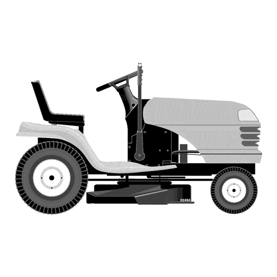
Owner's Manual
JCRRFTSMRN°J
LAWN TRACTOR
18.5 HP, 42" Mower
Electric Start
Automatic Transmission
Model No.
917.275762
[_
his product has a low emission engine which operates
differently from previously
built engines. Before you start the
engine, read and understand
this Owner's Manual.
IMPORTANT:
Read and follow all Safety
Rules and Instructions before
operating this equipment.
For answers to your questions
about this product, Call:
1-800-659-5917
Sears Craftsman Help Line
5 am - 5 pm, Mon - Sat
Sears, Roebuck and Co., Hoffman Estates, IL 60179 U.S.A
Visit our Craftsman
website:www.sears.com/craftsman
Advertisement

Related Manuals for Craftsman 917.275762


Summary of Contents for Craftsman 917.275762
- Page 1 Call: Read and follow all Safety 1-800-659-5917 Rules and Instructions before Sears Craftsman Help Line operating this equipment. 5 am - 5 pm, Mon - Sat Sears, Roebuck and Co., Hoffman Estates, IL 60179 U.S.A Visit our Craftsman...
-
Page 2: Table Of Contents
MaintenanceSchedule......18 Warranty..........2 Serviceand Adjustments.....23 Safety Rules.......... 3 ProductSpecifications......6 Storage..........29 AssemblyPre-Operation ......8 Troubleshooting ........30 Operation..........11 Repair Parts......... 34 Sears Service......B ack Cover Maintenance ........18 LIMITEDWARRANTYON CRAFTSMANRIDINGEQUIPMENT Fortwo (2) years from the date of purchase,if this CraftsmanRiding Equipmentis maintained,lubricatedand tuned up accordingto the instructionsin the owner'smanual, Sears will repair or replacefree of charge any parts that are found to be defectivein material or workmanshipaccordingto the guidelinesof coveragelisted below.Searswill... - Page 3 IMPORTANT:This cutting machineis capableof amputatinghandsand feet and throw- ing objects.Failureto observe the followingsafety instructionscould result in serious injury or death. • Never direct discharged material _,WARNING: In order to preventac- toward anyone. Avoid discharging cidental startingwhen setting up, trans- material against a wall or obstruction.
- Page 4 I1.SLOPE OPERATION • Never carry children, even with the Slopes are a major factorrelated to loss of blades shut off. They may fall off and controland tip-over accidents,which can be seriously injured or interfere with result in severeinjury or death. Opera- safe machine operation.
- Page 5 • Remove gas-powered equipment from • Keep machine free of grass, leaves, the truck or trailer and refuel it on the other debris build-up. Clean oil or fuel ground. If this is not possible, then spillage and remove any fuel-soaked debris.
-
Page 6: Productspecifications
PROTECTION W/O Filter: 3.0 Pints AGREEMENTS Spark Plug: Champion RC12YC Congratulations on making a smart pur- (GAP: .030") chase. Your new Craftsman@ product Ground Speed Forward: designed and manufactured for years (MPH): Reverse: dependable operation. But like all prod- Tire Pressure:... - Page 7 Steering Wheel Steering Wheel insert (1) Large Flat Washer Steering Steering Wheel Adapter Extension Boot Shaft Steering (1) 5/16 Lock Washer (1) Hex Bolt 5/16-18 Seat (1) Washer 17/32 x 1-3/16 x 12 Gauge _(1) Knob For Future Use Keys Slope Sheet...
- Page 8 Your new tractor has been assembled at the factory with the exception of those parts left unassembled for shipping purposes. To ensure safe and proper operation of your tractor all parts and hardware you assemble must be tightened securely. Use the correct tools as necessary to insure...
-
Page 9: Operation
Slide seat until a comfortable position NOTE: You may now roll or drive your is reached which allows you to press tractor off the skid. Follow the appropriate instruction below to remove the tractor clutch/brake pedal all the way down. from the skid. -
Page 10: Maintenance
CHECK TIRE PRESSURE V'CHECKLIST The tires on your tractor were overinflated Before you operate your new tractor, at the factory for shipping purposes. Cor- wish to assure that you receive the best rect tire pressure is importantfor best performance and satisfaction from this cutting performance. - Page 11 These symbols may appear on your tractor or in literature supplied with the product. Learn and understand their meaning. I'-,I REVERSE NEUTRAL HIGH CHOKE FAST SLOW IGNITION SWITCH ENGINE OFF REVERSE ENGINE ON ENGINE START PARKING BRAKE PARKING BRAKE PARKING BRAKE OPERATION LOCKED...
- Page 12 KNOW YOUR TRACTOR READ THIS OWNER'S MANUAL AND SAFETY RULES BEFORE OPERATING YOUR TRACTOR Compare the illustrations with your tractor to familiarize yourself with the locations various controls and adjustments. Save this manual for future reference. Ignition Switch Attachment ROS "ON" Position Clutch Lever ..
- Page 13 The operation of any tractor result in foreign objects thrown into the eyes, which can result in severe eye damage. Always wear safety glasses or eye shields while operating your tractor or performing any adjustments or repairs. We recommend standard safety glasses or a wide vision safety mask worn over spectacles.
- Page 14 TO ADJUST GAUGE WHEELS Attachment Attachemnt Clutch Lever Gauge wheels are properly adjusted "Engaged" High when they are slightly off the ground when Position Position mower is at the desired cutting height operating position. Gauge wheels then keep the deck in proper position to help Position...
- Page 15 TO OPERATE ON HILLS TOWING CARTS AND OTHER ATTACH- MENTS _,WARNING: Do not drive up or down Tow only the attachments that are recom- hills with slopes greater than 15 ° and do mended by and comply with specifications not drive across any slope.
- Page 16 TO START ENGINE AUTOMATIC TRANSMISSION WARM When starting the Before driving the unit in cold weather, engine for the first time the transmission should be warmed up as or if the engine has run out of fuel, it will follows: take extra cranking time to move fuel from Be sure the tractor...
-
Page 17: Serviceand Adjustments
NOTE: During this step there will be no movement of drive wheels. The air is being removed from hydraulic drive system. Move motion control lever to neutral position. Shutoff engine and set parking brake. Engage transmission by placing free- wheel control in engaged position... - Page 18 MA,.TE.A.CE SC.EOULE /_/_X'x_'_/_ " FILL IN DATES AS YOU COMPLETE /__/_ _/_/O.Oq. _" REGULAR SERVICE /_r/_'_d_VSERVlOE DATES Check Brake Operation Check Tire Pressure Check Operator Presence ROS Systems Check for Loose Fasteners Sharpen/Replace Mower Blades Lubrication Chart Check Battery Level Clean Battery and Terminals Check Transaxle...
- Page 19 TRACTOR CHECK REVERSE OPERATION (ROS) SYSTEM Alwaysobserve safetyrules when per- formingany maintenance. • When the engine is running with the BRAKE OPERATION ignition switch in the engine "ON" posi- tion and the attachment clutch engaged, If tractor requiresmore than five (5) feet to any attempt by the operator to shift into...
- Page 20 • To check blade balance, you will need a • Inspect cooling fins for dirt, grass clip- 5/8" diameter steel bolt, pin, or a cone pings and other materials. To prevent balancer. (When using a cone balancer, damage to seals, do not use com- follow the instructions supplied...
- Page 21 Oil Drain Valve Align tabs on cover with slots in blower housing and replace cover. Hook handle on cover and push down Closed on handle to close. IMPORTANT: Petroleum solvents, such Locked as kerosene, are not to be used to clean Position the cartridge.
- Page 22 MUFFLER CLEANING • Clean engine, battery, seat, finish, etc. Inspect and replace corroded muffler of all foreign matter. spark arrester (if equipped) as it could cre- • Keep finished surfaces and wheels free ate a fire hazard and/or damage. of all gasoline, oil, etc.
- Page 23 WARNING: SERVICE OR ADJUSTMENTS: TO AVOID SERIOUS INJURY, BEFORE PERFORMING Depress clutch/brake pedal fully and set parking brake. Place motion control lever in neutral (N) position. Place attachment clutch in "DISENGAGED" position. Turn ignition key to "STOP" and remove key. Make sure the blades and all moving parts have completely...
- Page 24 TO LEVEL MOWER HOUSING • When distance "D" is 1/8" to 1/2" lower at front than rear, tighten nuts "F" against Adjust the mower while tractor is parked trunnion on both front links. on level ground or driveway. Make sure tires are properly inflated (See "PRODUCT...
- Page 25 Mandrel With parking brake "Engaged" Idler "A" am Nut perating Pulley Do not touch this nut. If further brake TO CHECK AND ADJUST BRAKE adjustment is necessary contact a Sears other qualified service center, Your tractor is equipped with an adjustable brake system which is mounted on the...
- Page 26 TRANSMISSION REMOVAL/ REPLACEMENT Should your transmission require removal for Engine Pulley I service or replacement, it should be purged after reinstallation and before operating Clutching Idler_ tractor. See "PURGE TRANSMISSION" the Operation section of this manual. TO ADJUST STEERING WHEEL ALIGN- Stationary Idler j MENT...
- Page 27 If "jumpercables"are used for emergency starting, follow this procedure: IMPORTANT:Yourtractor is equipped with a 12volt system.The othervehicle must also be a 12volt system.Do not use your tractor battery to start other vehicles. TO ATTACHJUMPERCABLES- 1. Connect one end of the RED cable to the POSITIVE(+) terminal of each Terminal battery(A-B),taking care not to short...
- Page 28 ENGINE IMPORTANT: Damage to the needle valve and the seat in carburetor may result Maintenance, repair, or replacement of the if screw is turned in too tight. emission control devices and systems, which are being done at the customers expense, PRELIMINARY SETTING may be performed...
-
Page 29: Storage
Immediately prepare your tractor for stor- hose, or tank during storage. Also, alcohol age at the end of the season or if the trac- blended fuels (called gasohol or using tor will not be used for 30 days or more. ethanol or methanol) can attract... - Page 30 TROUBLESHOOTING CHART: See appropriate section in manual unless directed to Sears service center PROBLEM CAUSE CORRECTION Will not start 1. Out of fuel. Fill fuel tank. See "TO START ENGINE" Engine not "CHOKED" properly. Operation section. 3. Wait several minutes before Engine flooded.
- Page 31 TROUBLESHOOTING CHART: See appropriate section in manual unless directed to Sears service center PROBLEM CAUSE CORRECTION Loss of power Faulty spark plug. Clean and regap or change (cont.) spark plug. Dirty fuel filter. Replace fuel filter. Stale or dirty fuel. Empty fuel tank and refill tank with fresh, clean gasoline.
- Page 32 TROUBLESHOOTING CHART: See appropriate section in manual unless directed to Sears service center PROBLEM CAUSE CORRECTION Mower blades will 1. Obstruction in clutch Remove obstruction• not rotate mechanism• Worn/damaged mower drive Replace mower drive belt• belt. Frozen idler pulley• Replace idler pulley•...
- Page 33 TRACTOR - - MODEL NUMBER 917.275762 SCHEMATIC 02836 193374/390 BATTERY .I,, SOLENOID STARTER IGNITION UNIT ON TWIN CYL. ENGINES) BLUE HOUR BL_CK METER (OPTIONAL) BLUE CHARGING SYSTEM OUTPUT 28 VOLTS AC MIN. @ 3600 RPM 3 AMP DC @ 3600 RPM (CHARGING SYSTEM DISCONNECTED)
- Page 34 TRACTOR - - MODEL NUMBER 917.275762 ELECTRICAL...
- Page 35 TRACTOR - - MODEL NUMBER 917.275762 ELECTRICAL PART DESCRIPTION 163465 Battery 74760412 Bolt Hex Hd 1/4-20 unc x 3/4 176689 Box Battery 176138 Switch, Interlock 183759 Harness Asm Light W/4152j 4152J Bulb Light #1156 4799J Cable Battery 6 Ga. 11" red 146147 Cable Battery 175158...
- Page 36 TRACTOR - - MODEL NUMBER 917.275762 CHASSIS AND ENCLOSURES chassis-Laser-It.stir...
- Page 37 TRACTOR - - MODEL NUMBER 917.275762 CHASSIS AND ENCLOSURES PART DESCRIPTION 174619 Chassis 176554 Drawbar 17060612 Screw 3/8-16 x 3/4 155272 Bumper Hood/Dash 193510X012 Dash STD533710 Bolt, Carriage 3/8-16 x 3/4 174996 Panel, Dash, L.H. 172105X010 Panel, Dash, R.H. 17490608 Screw Thdrol 3/8-16 x 1/2 185682X613 Hood Assembly...
- Page 38 TRACTOR GROUND DRIVE " "MODEL NUMBER 917.275762 drive'hydro,st/L6 3...
- Page 39 TRACTOR - - MODEL NUMBER 917.275762 GROUND DRIVE PART PART DESCRIPTION DESCRIPTION Screw Hex Wsh Hi-Lo Transmission (See Breakdown) 142432 1/4 x 1/2 unc Hydro Gear Model 314-0510 192502 Rod, Shift 134683 Guide, Belt, Mower Drive RH STD561210 Pin, Cotter 1/8 x 1 169183 Strap, Torque, Lh STD551125...
- Page 40 TRACTOR - - MODEL NUMBER 917.275762 STEERING ASSEMBLY ..m_ .._D _ _-_- J" steering pl.lt 57...
- Page 41 TRACTOR - - MODEL NUMBER 917.275762 STEERING ASSEMBLY PART DESCRIPTION 186780 Steering Wheel 184706 Axle Assembly Cast Iron 169840 Spindle Assembly, L.H. 169839 Spindle Assembly, R.H. 626614 Bearing, Race, Thrust, Hardened 121748X Washer 25/32 x 1-5/8 x 16 Ga. 12000029 Ring, Klip 175121 Draglink...
- Page 42 TRACTOR - - MODEL NUMBER 917.275762 ENGINE OPTIONAL EQUIPMENT Spark Arrester engine-bs.lcyl PART PART DESCRIPTION DESCRIPTION 137040 170545X505 Line, Fuel Control, Throttle/Choke 181654 17720408 Plug Drain Oil Easy Screw, Hex Head, Thread 17670412 Screw, Hex Washer Head, Cutting 1/4-20 x 1/2 Thd., Roll.
- Page 43 TRACTOR - - MODEL NUMBER 917.275762 SEAT ASSEMBLY seat It.knob PART PART DESCRIPTION DESCRIPTION 180597 Seat 174648 Bracket Pnt Mounting Switch 180166 121248X Bracket Pnt Pivot Seat (blk) Bushing Snap BIk Nyl 50 Id 71110616 Bolt Fin Hex 3/8-16 unc x 1 72050412 Bolt Rdhd Sht Nk 1/4-20 x 1-1/2 19131610...
- Page 44 184311X428 Decal HP Engine Pad, Footrest RH STLT 172331 Decal Mower Srs 199993 Manual, Owner's, English 186282 199994 Decal Fender, Craftsman Manual, Owner's, Spanish 156439 Decal Fender Danger 186283 Decal Panel Side 146046 Decal V-Belt Drive Schematic 191551 Decal Chassis...
- Page 45 TRACTOR - - MODEL NUMBER 917.275762 LIFT ASSEMBLY • /"_ 13 ..-...._ 31_ lift-rh=l piece3 KEY PART PART NO. NO. DESCRIPTION DESCRIPTION 159460 Washer Asm Inner Spring W/ STD624008 Retainer Spring 173288 Link Front Plunger 159471 Shaft Asm. Lift 73350800 Nut Jam Hex 1/2-13 unc 105767X Pin Groove...
- Page 46 TRACTOR - - MODEL NUMBER 917.275762 MOWER DECK 113 1 _116 118"_ 42 D man-t-path stlt...
- Page 47 TRACTOR - - MODEL NUMBER 917.275762 MOWER DECK PART PART DESCRIPTION DESCRIPTION 165892 Mower Deck Assembly, 42" 133944 Washer, Hardened STD533107 Bolt 139888 Bolt, Shoulder 5/16-18 unc 138017 Bracket Assembly, Sway Bar, 184907 Arm Assembly, Pad, Brake Front 178515 Washer, Hardened 165460 Bracket Sway Bar 38/42"...
- Page 48 I'-- i .-'C €o "4 u108 [125 SEALANT 20W50 78.80Z 127- SEAL O-RING...
- Page 49 TRACTOR - - MODEL NUMBER 917.275762 HYDRO TRANSAXLE - - MODEL NUMBER 314-0510 PART PART DESCRIPTION DESCRIPTION 170351 Kit, Main Housing 170410 Hfhcs 1/4-20 X 2 W/patch, Special Main Housing, Machined Flange Bushing .865 X .985 X .790 142892 Bolt, Nylok 170352 Kit, Side Housing 170411 Spacer, Brake Torsion Spring...
- Page 50 TRACTOR - - MODEL NUMBER 917.275762 BRIGGS & STRATTON ENGINE-MODEL NUMBER 31P777, TYPE NUMBER 0299-E1 552C_691 @ 4[_,_J _0350 43 ,_ 684_, 11 _ 1330 REPAIR MANUAL 307_ 1264 1 11329 REPLACEMENT ENGINEI 358 ENGINE GASKET 146o_ 8680 3 (_ 1270 9430 741_...
- Page 51 TRACTOR - - MODEL NUMBER 917.275762 BRIGGS & STRATTON ENGINE-MODEL NUMBER 31P777, TYPE NUMBER 0299-E1 1095 VALVE GASKET 1022 238 @ 1022 6170 1022 404 # 614 _ 1267 1070 1051& 1005 1044_ 1040 363# 3o5 _...
- Page 52 TRACTOR - - MODEL NUMBER 917.275762 BRIGGS & STRATTON ENGINE-MODEL NUMBER 31P777, TYPE NUMBER 0299-E1 105A I 127A 1270 276A@ 947A NIKKIJ 1127 1266A O 9771_ARBURETOR GASKET 0Olg 527_ 1370276@ 12660 121A CARBURETOR OVERHAUL 121 CARBURETOR OVERHAUL 6170 231_ 987L_ 104 _' 1270 634A_...
- Page 53 TRACTOR - - MODEL NUMBER 917.274762 BRIGGS & STRATTON ENGINE-MODEL NUMBER 31P777, TYPE NUMBER 0299-E1 PART PART DESCRIPTION DESCRIPTION 697174 Cylinder Assembly 690577 O Seat-Inlet 399265 Kit-Bushing/Seal (Magneto Side) 690464 Valve-Choke (Manual Choke) 391086 ° Seal-Oil (Magneto Side) 108A 695419 Valve-Choke (Nikki) 697188 Sump-Engine...
- Page 54 TRACTOR - - MODEL NUMBER 917.275762 BRIGGS & STRATTON ENGINE-MODEL NUMBER 31P777, TYPE NUMBER 0299-E1 PART PART DESCRIPTION DESCRIPTION Terminal-Spark Plug 690323 Bolt (Starter Motor) 692424 497608 Brush Set 690968 •+ Seal-Valve Screw (Rocker Cover) 495859 Armature-Magneto 691108 • SeaI-O Ring (Oil Pump Cover) 691061 Screw (Magneto Armature) 690589...
- Page 55 SUGGESTED GUIDE FOR SIGHTING SLOPES FOR SAFE OPERATION ONLY RIDE UP AND DOWN HILL, NOT ACROSS HILL 15 DEGREES MAX. down the face of slopes, never across the face. Do not mow ARNING: To avoid serious injury, operate your tractor up and slopes greater than 15 degrees.
- Page 56 ©Sears, Roebuck and Co, ®Registered Trademark / TMTrademark / SMService Mark of Sears, Roebuck and Co. ® Marca Registrada / TMMarca de Fabrics / SMMarca de Servicio de Sears, Roebuck and Co. MCMarque de commerce / MOMarque depos6e de Sears, Roebuck and Co. 199993 07.25.05 Printed...
Need help?
Do you have a question about the 917.275762 and is the answer not in the manual?
Questions and answers
What size drive belt do I need for my riding lawnmower mower M#917.275761