Table of Contents
Advertisement
Available languages
Available languages
8_
Owner's Manual
CRAFTSMAN °
7 HORSEPOWER
24" TWO STAGE TRACK DRIVE
SNOW THROWER
Model No.
247.885570
/
/
m
CAUTION:
Before using this
product,
read this manual
and follow all Safety Rules
and Operating
Instructions.
Sears, Roebuck
And Co., Hoffman
Estates,
IL 60179 USA
770-0372M
8/96
Printed in U.S.A.
(R960823)
Advertisement
Table of Contents

Related Manuals for Craftsman 247.885570


Summary of Contents for Craftsman 247.885570
- Page 1 Owner's Manual CRAFTSMAN ° 7 HORSEPOWER 24" TWO STAGE TRACK DRIVE SNOW THROWER Model No. 247.885570 CAUTION: Before using this product, read this manual and follow all Safety Rules and Operating Instructions. Sears, Roebuck And Co., Hoffman Estates, IL 60179 USA...
- Page 2 Sears will repair, free of charge, any defect in material and workmanship. If this Craftsman snow thrower is used for commercial or rental purposes, this warranty applies for only 30 days from the date of purchase.
- Page 3 and/or property ofyourself and others. Read a nd follow allinstructions inthismanual before a ttempting to This symbol points o ut i mportant safety i nstructions which, ifnotfollowed, could endanger the personal safety operate y our s now thrower. Failure tocomply with these instructions may result inpersonal injury.
- Page 4 NO IMAGE AVAILABLE...
- Page 5 IMAGE AVAILABLE...
- Page 6 IMPORTANT: This engine has been shipped without part numbers listed on page 5. Lay each hardware piece gasoline or oil. After assembly, see operation section on the picture and match the size. of this manual for proper fuel and engine oil recom- SETTING UPYOUR SNOWTHROWER...
- Page 7 ATTACHING THE SHIFT ROD • Attach handle panel to the handle with four car- riage bolts, cupped washers (cupped side against • Place the shift lever in the sixth (6) speed position. the handle panel) and hex nuts as shown in figure •...
- Page 8 • Place one 3/8 ID flat washer on the end of the • After assembling all three chute flange keepers, tighten then back off 1/4 turn to allow easier chute crank, then insert the end of the crank into movement of the chute. Use (2) 7/16" wrenches. the eye hole in the plastic bushing in the chute crank bracket.
- Page 9 ATTACHING L EFTANDRIGHT TURN TRIGGERS TRACTION DRIVE CONTROL ADJUSTMENT • Remove the screw from the top of the right hand turn • To check the adjustment of the traction drive con- trigger. Be careful not to lose the weld nut. Remove trol and shift lever, move the weight transfer lever the trigger from the cable by pulling the cable out and to the transport position (see figure 16) and the...
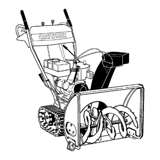
- Page 10 KNOW YOUR SNOW THROWER READ THIS OWNER'S MANUAL AND SAFETY RULES BEFORE OPERATING YOUR SNOW THROWER. Compare the illustrations in this manual with your snow thrower to familiarize yourself with the location of various controls and adjustments. Save this manual for future reference. Fuel Cap Oil Fill Plug Spark Plug...
- Page 11 The operation of any snow thrower can result in foreign objects being thrown into the eyes, which can result in severe eye damage. Always wear safety glasses or eye shields while operating the snow thrower or performing any adjustments or repairs. We recommend standard safety glasses or wide vision safety mask for over your glasses available at SEARS retail stores.
- Page 12 TO STOP THE SNOW THROWER • Interlock feature will allow you to remove your left hand from the auger control lever. • To stop the track, release the traction drive lever. • When clearing your first pass through the snow, •...
- Page 13 Storegasoline inaclean,approved container, a nd keepthecapinplaceonthecontainer. erly grounded at all times to avoid the possi- WARNING: The electric starter must be prop- bility of electric shock which may be injurious • Make sure that the container from which you pour to the operator.
- Page 14 WARM START • Allow the engine to warm up for a few minutes be- cause the engine will not develop full power until it • If restarting a warm engine after a shut down, ro- reaches operating temperature. tate choke to OFF instead of FULL and do not •...
- Page 15 CUSTOMER RESPONSIBILITIES MAINTENANCE SCHEDULE DATES* Lubricate pivot points Clean snow thrower I,.- Clean shave plate Clean skid shoes Check V-Belts Check friction wheel rubber Check engine oil Change engine oil Service air cleaner Check spark plug Check muffler * Fill in dates as you complete regular service _/ Check SPROCKET SHAFT GENERAL...
- Page 16 CHECK V-BELTS GEAR CASE • The gear case is lubricated with grease at the • Remove the plastic belt cover on the front of the en- factory and does not require checking. If gine by removing two self-tapping screws. disassembled for any reason, lubricate with 2 •...
- Page 17 ENGINE • With the traction drive control engaged, make sure that the friction wheel is making contact with the ENGINE OIL friction plate. See figure 18. Also make sure that • Only use high quality detergent oil rated with API the overtravel spring is stretched.
- Page 18 • Push down on the shift rod (and shift arm assem- bly) as far as it will go. Hold it in this position. • Thread the ferrule up or down the shift rod as necessary until the ferrule lines up with the upper hole in the shift lever.
- Page 19 • Tip the snow thrower up and forward, so that it rests on the housing. Drive Belt • Remove four self-tapping screws from the frame cover underneath the snow thrower. • Using a 7/8" wrench to hold the shaft, loosen, but do not completely remove, the hex bolt and bell washer from the left end of the shaft.
- Page 20 Shift Rod Spacer Sprocket Assembly FrictionWheel Assembly Bracl ;haft FIGURE 26 NOTE: Do not drain carburetor if using fuel stabilizer, WARNING: Never store engine with fuel in Never use engine or carburetor cleaning products in tank indoors or in poorly ventilated areas, the fuel tank or permanent damage may occur.
- Page 21 Trouble PossibleCause(s) Corrective Action Shift lever not locking 1. Shift rod out of adjustment. 1. Remove washer and pin. Turn into 6th ferrule clockwise one turn and reinstall. Engine fails to start 1. Fuel tank empty, or stale fuel. 1. Fill tank with clean, fresh gasoline. 2.
- Page 23 SEARS CRAFTSMAN 7 H.P. SNOW THROWER MODEL 247.885570 PART PART DESCRIPTION QTY. DESCRI PTION QTY. 684-0008-0637 Shift Arm Assembly 736-0509 Washer 684-0022 Chute Crank Assembly 737-0133 Plastilube 684-0032A Handle Panel Assembly 741-0475 Plastic Bushing 684-0112 746-0896 Control Cable Handle Assy. Engagement RH i 684-0111 Handle Assy.
- Page 24 ®\...
- Page 25 SEARS CRAFTSMAN 7 H.P. SNOW THROWER MODEL 247.885570 PART PART DESCRIPTION QTY. DESCRIPTION QTY. 611-0053 719-0295A Axle Assembly Housing Track 618-0043 725-0157 Cable Tie Dog Assembly--R.H. 618-0044 732-0209 Dog Assembly --L.H. Spring 618-0169 732-0264 Shaft Assembly Spring 656-0012A 736-0105 Bell Washer...
- Page 26 ® ®...
- Page 27 SEARS CRAFTSMAN 7 H.P. SNOW THROWER MODEL 247.885570 KEY i PART PART KEY i QTY. DESCRIPTION QTY. DESCRIPTION 738-0140 Shoulder Screw 631-0032 Wheel Assembly Idler 748-0353A Lift-Shaft Drive 684-0009 Rod Track Pivot 750-0547 684-0024 Spacer Axle Assembly 750-0909 Spacer 684-0038...
- Page 29 SEARS CRAFTSMAN 7 H,P, SNOW THROWER MODEL 247.885570 PART PART I KEY QTY, I DESCRIPTION I DESCRIPTION 731-1379 05931 i Housing-Bearing Adapter-Chute 732-0611 605-5189-0637 Spring •4 Spiral Assembly--L.H. 736-0119 Lock Washer 605-5188-0637 Spiral Assembly--R.H. 736-0167 Flat Washer 618-0120 Gear Assembly...
- Page 30 SEARS CRAFTSMAN 7 H.P. SNOW THROWER MODEL NO. 247.885570 "-- PART PART DESCRIPTION QTY. DESCRIPTION QTY, 05896A Bracket 736-0331 Washer 736-0505 Washer 629-0071 Extension Cord 748-0234 Shoulder Spacer 710-0117 Screw 748-0360 710-0157 Screw Pulley Adapter 754-0346 V-Belt 710-0230 Screw 754-0430...
- Page 31 SEARS CRAFTSMAN 7 H.P. ENGINE MODEL NO. 143.977001 FOR SNOW THROWER MODEL NO. 247.885570 RECOIL STARTER PART DESCRIPTION QTY. Recoil Starter ___1/3__ 590707 590599A Spring Pin Washer 590696 Retainer Washer 590601 590600 590697 Brake Spring 590698 Starter Dog Dog Spring...
- Page 32 SEARS CRAFTSMAN 7 H.P. ENGINE MODEL NO. 143.977001 FOR SNOW THROWER MODEL NO. 247.885570 264A 370A...
- Page 33 SEARS CRAFTSMAN 7 H.P. ENGINE MODEL NO. 143.977001 FOR SNOW THROWER MODEL NO. 247.885570 PART PART DESCRIPTION QTY. DESCRIPTION 32586C 30588A Cylinder (Incl. 2 & 20) Governor Spool 27652 Dowel Pin 29193 Retaining Ring 30968 Oil Drain Extension 650488 Screw, t/4-20 x 1-1/4"...
- Page 34 SEARS CRAFTSMAN 7 H.P. ENGINE MODEL NO. 143.977001 FOR SNOW THROWER MODEL NO. 247.885570 Table continued from page 33. PART PART QTY. DESCRIPTION QTY. DESCRIPTION Carburetor Cover 35060 35755 Blower Housing 650765 Screw, 10-32 x 1/2" 29747B Screw, Torx T-40, 5/16-24 650760 Screw, 8-32 x 3/8"...
- Page 35 SEARS CRAFTSMAN 7 H.P. ENGINE MODEL NO. 143.977001 FOR SNOW THROWER MODEL NO. 247.885570 ELECTRIC STARTER PART DESCRIPTION 33328D Electric Starter (110 Volt) 33842 Retainer Ring 33430 Spring Retainer 33431 Anti-drift Spring 33432 Gear 35893 Retainer & Nut 35449 Drive End Cap Assy.
- Page 36 .717 Revised 8-31-93 >15...
- Page 37 SEARS CRAFTSMAN 7 H.P. ENGINE MODEL NO. 143.977001 FOR SNOW THROWER MODEL NO. 247.885570 CARBURETOR PART REF_ I QTY. DESCRIPTION 632371A Carburetor 31834 Throttle Shaft & Lever Assy 631767 Throttle Return Spring 631036 Throttle Shutter 650506 Shutter Screw 632373 Choke Shaft...
- Page 38 Fortherepairorreplacement p arts youneed delivered directly toyourhome Call7 am - 7 pm, 7 daysa week 1.800.366.PART (1-800-366-7278) Forin-homemajorbrandrepairservice Call24 hoursa day,7 daysa week 1-800-4-REPAIR (1-800-473-7247) Forthelocation o fa SEARS Sears Parts andRepairCenter i nyour area F_ Immmmm mmmmm| Call 24 hoursa day,7 daysa week 1-800-488-1 Forinformation onpurchasing a Sears Maintenance A greement o rto inquire...
- Page 39 _SManual Del Propietario CRAFTSMAN° EXPULSOR DE NIEVE 7 CABALLOS DE FUERZA PROPULSION DE ORUGA DE DOS ETAPAS DE 24" No. De Modelo 247.885570 Precauci6n: Lea y siga todas las regtas e instrucciones seguridad antes de operar este equipo. Sears, Roebuck And Co., Hoffman...
- Page 40 DE NIEVE CRAFTSMAN Per un a5o desde la fecha de compra cuando este expulsor de nieve Craftsman sea mantenido, lubricado y puesto a punto de acuerdo con tas instrucciones de operaci6n y mantenimiento en el manual del propietario, Sears reparara libre de costo cualquier defecto de material o de mane de obra.
- Page 41 ESTE SIMBOLO INDICA INSTRUCCIONES IMPORTANTES DE SEGURIDAD LAS CUALES, SI NO SE SIGUEN, PUEDEN PONER EN PELIGRO LA SEGURIDAD PERSONALY/O LA PROPIEDAD SUYAY AJENA. ANTES DE INTENTAR OPERAR SU EXPULSOR DE NIEVE LEAY SIGATODAS LAS INSTRUC- CLONES EN ESTE MANUAL. LA FALTA DE CUMPLIMIENTO CON ESTAS INSTRUCCIONES PUEDE RESULTAR EN LESIONES PERSONALES.
- Page 42 • No intente sobrecargar la capacidad de la mdquina in- • Si el expulsor de nieve va a ser almacenado durante un tentando despejar la nieve a una velocidad demasiado periodo prolongado de tiempo, refi_rase siempre alas elevada: Nunca opere la m,_quina a altas velocidades de instrucciones en la guia del propietario para detalles im- transporte sobre superficies resbalosas.
- Page 43 Despliegue la ferreterfa de acuerdo con la itustraciTn para fines de identificaci6n. Las piezas est_,n ilustradas a la mitad de su tamafio aproximadamente. Los mimeros de pieza se muestran entre parentesis. (El paquete de ferreterfa puede contener artfculos adicionales que no se usan en su unidad) I FIJACIONDELCON JUNTODE LA CANALETA A__ FIJACION DEL CONJUNTO...
- Page 44 IMPORTANTE: Esta unidad ha side despachada sin PREPARACION DE SU EXPULSOR DE NIEVE gasolina ni aceite. Despu_s del ensamblado, vea la ADVERTENCIA: Antes de ensamblar secci6n de operaciones de este manual para las recomendaciones sobre combustible y aceite de expulsor de nieve, asegdrese que el cable de la bujia estd desconectado y que est_ motor apropiados.
- Page 45 ATTACHING FIJACION DE LA MANIVELA DE LA • Alinee los orificios en el mango con los orificios a CANALETA los dos lades del panel del mango. • Inserte el pemo hexagonal a trav6s del soporte su- • Asegure la parte posterior del panel dei mango con perior de la manivela de la canaleta, Vea la figura 5.
- Page 46 • Una vez que el casquillo se desliza dentro del • Deslice los cables que se extienden desde el panel orificio, retroceda una vuelta completa en sentido del mango a la canaleta dentro de la gu[a de cable contrario alas agujas del reloj al casquillo con la ubicada en el tope del motor.
- Page 47 FIJACION DE LOS GATILLOS PARA GIRO AJUSTE DEL CONTROL DEL PROPULSOR DE IZQUIERDO Y DERECHO TRACCION Y DE LA PALANCA DE CAMBIOS • Extraiga el tomillo del tope del gatillo de giro dere- • Para inspeccionar el ajuste del control del propul- cho.
- Page 48 CONOZCA SU EXPULSOR DE NIEVE ANTES DE HACER FUNCIONAR SU EXPULSOR DE NIEVE LEA ESTE MANUAL DEL PROPIETARIO Compare las ilustraciones en este manual con su expulsor de nieve para familiarizarse con la ubicaci6n de varios controles y ajustes. Guarde este manual para referencia futura. Tapa de Tap6n de Ilenado de aceite...
- Page 49 La operaci6n de un expulsor de nieve puede resultar en objetos despedidos contra los ojos, Io que puede resultar en lesiones graves de los ojos. Mientras opera el o efect_a ajustes o reparaciones al expulsor de nieve use siempre lentes de seguridad o protectores de los ojos. Recomendamos tentes est_mdar de segu- ridad o una mascara de seguridad de visiSn amplia para colocar sobre sus lentes, disponible en sus tiendas minoristas de Sears.
- Page 50 DETENCION DEL EXPULSOR DE NIEVE Gasolina • Para detener la expulsi6n de nieve, desenganche la palanca det propulsor de la h_lice. ACEITE • Para detener las orugas, suelte la palanca del pro- pulsor de tracciSn. • Para apagar el motor, empuje la palanca de con- trol del acelerador a OFF y extraiga la Ilave de en- cendido.
- Page 51 PARA ARRANCAR EL MOTOR • Presione el bot6n del cebador mientras cubre el orificio de ventilaci6n come sigue: (Retire el dedo (ARRANCADOR ELECTRICO) del bot6n del cebador entre cebados). Aseg_rese que el motor tiene suficiente aceite. El No cebe si la temperatura es mayor que 50°E motor del expulsor de nieve est,.
- Page 52 • Permita que el motor se caliente durante unos po- Con el motor sin funcionar, frote para limpiar toda cos minutes ya que el motor no desarrollara la nieve y la humedad del carburador que cubre el plena potencia hasta que alcance la temperatura _.rea de la palanca de control.
- Page 53 Responsabilidades del cliente ½,-'% y c.,s /#/o.,,/,_./o,-/o_..,./#. PROGRAMA DE MANTENIMIENTO DE SERVIClO* Lubrique los puntos de pivote Limpie el expulsor de nieve I-.- Limpie la placa raspadora Limpie ]as zapatas deslizantes Inspeccione las correas en V Inspecoione la goma de la rueda de fricci6n Inspeccione el aceite del motor Cambie el aceite del motor...
- Page 54 CAJA DE ENGRANAJES guramente. Extraiga la varilla de nivel de aceite. Si el aceite no estA hasta la marca "FULL" de la varil- • La caja de engranajes estA lubricada con grasa de la de nivel de aceite, agregue el aceite re- fAbrica y no requiere inspecci6n.
- Page 55 • Separe el armaz6n del conjunto del armazbn EXTRACCION Y REEMPLAZO DE LA para.ndose en la posici6n operativa y levantando CORREA de los mangos. El armazSn y la armadura se sep- ADVERTENCIA: Desconecte el conductor de la arar&n, y la correa propulsora posterior de la h_lice saldr_, de la polea.
- Page 56 • Deslice lacorreaentrela rueda defricci6n y lapla- • Mueva la palanca de transferencia de peso a la cadeldiscodefricci6n. V ealafigura23.Vuelva a posici6n de nieve compactada. Refierase a la ensamblar siguiendo l asinstrucciones enorden figura 16. inverso. • Golpee suavemente la cabeza del perno para des- NOTA: L a mensula de soporte debe apoyarse sobre el prender el rodamiento a bolillas de! lade derecho...
- Page 57 Advertencia: Antes de efectuar cualquier • Con el control del propulsor desenganchado, aseg- Qrese que haya espacio entre la rueda de fricci6n y ajuste o reparaci6n, siempre apague el motor, desconecte el cable de la bujfa y la placa de fricciSn en todas las posiciones de la al6jelo de la bujfa.
- Page 58 ADVERTENCIA: Nunca almacene el motor • Extraiga la bujfa y vierta una (1) onza de aceite de motor a traves del orificio de la bujfa dentro del cil- con combustible en el tanque, bajo techo o en _.reas mal ventiladas, donde los humos indro.
- Page 59 Accion Correctora Problerna Causa(s) posible El motor no arranca 1. Llene el tanque con combustible 1. Tanque de combustible vacio, o combustible rancio. limpio y fresco. 2. Abra ta vdlvuta de corte.. 2. Est_ cerrade la v_lvula de corte del combustible. 3.
- Page 60 Sears se complace en ofrecer a sus clientes servicio de reparacibn de aparatos electro- dom_sticos y electrbnicos de todas las marcas. En Sears, usted puede contar con operadores en espa_ol, a los que puede Ilamar sin cargo alguno. Para pedir servicio de reparaci6n a domicilio, Llame 24 horas al d(a, 7 dias a la semana 1 800-676-5811...
Need help?
Do you have a question about the 247.885570 and is the answer not in the manual?
Questions and answers