
Subscribe to Our Youtube Channel
Related Manuals for Asus TUV4X


Summary of Contents for Asus TUV4X
- Page 1 ® TUV4X JumperFree™ PC133/VC133 133MHz FSB AGP Pro/4X Socket 370 Motherboard USER’S MANUAL...
- Page 2 Product warranty or service will not be extended if: (1) the product is repaired, modified or altered, unless such repair, modification of alteration is authorized in writing by ASUS; or (2) the serial number of the product is defaced or missing.
-
Page 3: Asus Contact Information
ASUS COMPUTER GmbH (Europe) Marketing Address: Harkortstr. 25, 40880 Ratingen, BRD, Germany Fax: +49-2102-442066 Email: sales@asuscom.de (for marketing requests only) Technical Support Hotline: MB/Others: +49-2102-9599-0 Notebook: +49-2102-9599-10 Fax: +49-2102-9599-11 Support (Email): www.asuscom.de/de/support (for online support) WWW: www.asuscom.de FTP: ftp.asuscom.de/pub/ASUSCOM ASUS TUV4X User’s Manual... -
Page 4: Table Of Contents
1. INTRODUCTION ................7 1.1 How This Manual Is Organized ........... 7 1.2 Item Checklist ................7 2. FEATURES ..................8 2.1 ASUS TUV4X Motherboard ............8 2.1.1 Specifications ..............8 2.1.2 Performance ..............10 2.1.3 Intelligence ............... 11 2.2 Motherboard Components ............12 2.2.1 Component Locations ............ - Page 5 4.7 Exit Menu ................... 78 5. SOFTWARE SETUP ............... 81 5.1 Operating Systems ..............81 5.1.1 Windows 98 First Time Installation ......... 81 5.2 TUV4X Motherboard Support CD ..........81 5.2.1 Installation Menus ............81 5.2.2 Applications ..............82 6. SOFTWARE REFERENCE ............85 6.1 ASUS PC Probe .................
-
Page 6: Federal Communications Commission Statement
Radio Interference Regulations of the Canadian Department of Communications. This Class B digital apparatus complies with Canadian ICES-003. Cet appareil numérique de la classe B est conforme à la norme NMB-003 du Canada. ASUS TUV4X User’s Manual... -
Page 7: Introduction
UltraDMA/33 IDE drives ASUS PCI-L101 Wake-On-LAN (1) Ribbon cable for two 3.5” 10/100 Ethernet Card floppy disk drives (1) ASUS Support CD with drivers and utilities (1) Bag of spare jumper caps (1) ASUS 2-port USB Connector (1) User’s Manual... -
Page 8: Features
Powered by Intel Pentium III/Coppermine processors, the TUV4X motherboard comes bundled with advanced features to provide outstanding performance. The TUV4X packs in more value by offering plenty of room for expansion making it truly flexible. 2.1.1 Specifications • Latest Processor Support ®... - Page 9 • PC Health Monitoring: Provides an easy way to examine and manage system status information, such as CPU and system voltages, temperatures, and fan status through the onboard hardware ASUS ASIC and the bundled ASUS PC Probe. • SMBus: Features the System Management Bus interface used to physically transport commands and information between SMBus devices.
-
Page 10: Performance
ACPI benefits, use an ACPI-supported OS such as Windows 98/ME/2000. • PC’99 Compliant: Both the BIOS and hardware levels of ASUS smart series motherboards are PC’99 compliant. The new PC’99 requirements for systems and components are based on the following high-level goals: Support for Plug-... -
Page 11: Intelligence
• Chassis Intrusion Detection: Supports chassis-intrusion monitoring through the ASUS ASIC. A chassis intrusion event is kept in memory on battery power for more protection. ASUS TUV4X User’s Manual... -
Page 12: Motherboard Components
USB Connectors (Port 2 & Port 3) ........10 1 PS/2 Mouse Connector ..........(Top) 25 1 PS/2 Keyboard Connector ........(Bottom) 25 Hardware Monitoring System Voltage Monitoring (integrated in ASUS ASIC) ..11 Fan Power and Speed Monitoring Connectors Onboard Audio (on audio models only) Audio Chipset ................. -
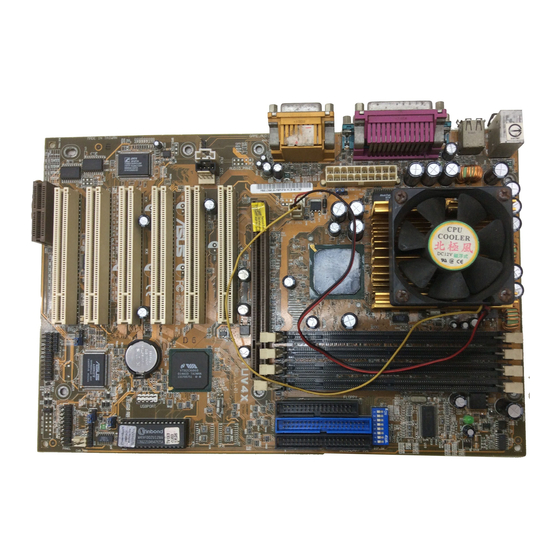
Page 13: Component Locations
2. FEATURES 2.2.1 Component Locations ASUS TUV4X User’s Manual... -
Page 14: Hardware Setup
PANEL Audio Modem Riser AFPANEL IDELED (AMR) NOTE: The audio chipset, external GAME/AUDIO connectors, and internal audio connectors are optional components, and present in audio models only. The components are grayed in the above motherboard layout. ASUS TUV4X User’s Manual... -
Page 15: Layout Contents
39 USB Header (10-1 pin) 18) ATXPWR p. 40 ATX Power Supply Connectors (20-pin) 19) AFPANEL p. 41 ASUS iPanel Connector (12-1 pin) 20) MIC2 p. 41 Internal Microphone Connector (3-pin) 21) CD/AUX/MODEM p. 42 Internal Audio Connectors (three 3-pin) 22) PWR.LED (PANEL) -
Page 16: Hardware Setup Procedure
Failure to do so may cause severe damage to the motherboard, peripherals, and/or components. (TIP: When lit, the onboard LED indicates that the system is in suspend or soft-off mode, not powered OFF.) TUV4X Standby Powered ® Power TUV4X Onboard LED ASUS TUV4X User’s Manual... - Page 17 Enable (JumperFree) [2-3] (default) Disable (Jumper) [1-2] DIP_SW 1 2 3 4 5 6 7 8 TUV4X ® Jumper JumperFree Mode Mode (Default) TUV4X JumperFree™ Mode Setting NOTE: In JumperFree™ mode, set all DIP switches (DIP_SW) to OFF. ASUS TUV4X User’s Manual...
- Page 18 Set the CPU frequency only to the recommended settings. Frequencies other than the recommended CPU bus frequencies are not guaranteed to be stable. Overclocking the processor is not recommended. It may result in a slower speed. ASUS TUV4X User’s Manual...
- Page 19 5 6 7 8 1 2 3 4 5 6 7 8 6.5x 7.0x 7.5x TUV4X CPU Frequency Multiple Selection 1 2 3 4 5 6 7 8 1 2 3 4 5 6 7 8 8.0x Test ASUS TUV4X User’s Manual...
- Page 20 Celeron 333MHz 5.0x 66MHz [OFF] [OFF] [ON] [ON] [ON] [OFF] [OFF] [ON] Celeron 300MHz 4.5x 66MHz [OFF] [OFF] [ON] [ON] [OFF] [ON] [OFF] [ON] Celeron 266MHz 4.0x 66MHz [OFF] [OFF] [ON] [ON] [ON] [ON] [OFF] [ON] ASUS TUV4X User’s Manual...
- Page 21 (2) short the solder points, (3) plug and turn ON the computer, (4) hold down the <Del> key during the boot process and enter BIOS setup to re-enter data. CR2032 3V TUV4X Lithium Cell CMOS Power ® CLRTC Short solder points TUV4X Clear RTC RAM to Clear CMOS ASUS TUV4X User’s Manual...
- Page 22 3. The total current consumed must NOT exceed the power supply capability (+5VSB) whether under normal working conditions or in sleep mode. USB_PWR0 Disable Enable (Default) TUV4X USB_PWR1 ® Disable Enable (Default) TUV4X USB Device Wake Up ASUS TUV4X User’s Manual...
-
Page 23: System Memory
For the system CPU bus to operate MHz/133MHz, use only PC100-/PC133- compliant DIMMs. • ASUS motherboards support Serial Presence Detect (SPD) DIMMs. This is the memory of choice for best performance vs. stability. • SDRAM chips are generally thinner with higher pin density than EDO (Extended Data Output) chips. -
Page 24: Memory Installation
TUV4X ® 60 Pins 20 Pins TUV4X 168-Pin DIMM Sockets Lock The DIMMs must be 3.3Volt unbuffered SDRAMs. To determine the DIMM type, check the notches on the DIMMs (see the figure below). The notches on the DIMM shifts between left, center, or right to identify the type and also to prevent the wrong type from being inserted into the DIMM slot on the motherboard. -
Page 25: Central Processing Unit (Cpu)
Install an auxillary fan, if necessary. CAUTION! Be careful not to scrape the motherboard when mounting/unmounting a clamp-style processor fan to avoid damaging the motherboard. Proceed to the next section for the steps on how to properly install a CPU. ASUS TUV4X User’s Manual... -
Page 26: Cpu Installation
Refer to the installation instructions that came with the heatsink and fan. NOTE: Do not forget to set the correct Bus Frequency and Multiple (frequency multiple setting is available only on unlocked processors) for the processor to avoid start-up problems. ASUS TUV4X User’s Manual... -
Page 27: Expansion Cards
4. Secure the card to the slot with the screw you removed earlier. 5. Replace the system cover. 6. Change the necessary BIOS settings, if any. (see section 4.4.3 PCI Configuration to change the settings.) 7. Install the necessary software drivers for the expansion card. ASUS TUV4X User’s Manual... -
Page 28: Assigning Irqs For Expansion Cards
— — PCI slot 6 — — shared — AGPPro slot shared — — — AMR slot — shared — — Onboard Audio controller — — shared — Onboard USB controller — — — shared ASUS TUV4X User’s Manual... -
Page 29: Accelerated Graphics Port (Agp) Pro Slot
20-pin bay 28-pin bay Rib (inside slot) TUV4X Accelerated Graphics Port (AGP PRO) CAUTION! The AGP Pro slot is shipped with a warning label over the 20-pin bay. DO NOT remove this label and the safety tab underneath it if you will be using an AGP card without a retention notch. -
Page 30: Audio Modem Riser (Amr) Slot
ASUS MR-1 Unlike that of standard cards, the component side of the specially-designed AMR card faces the motherboard’s TUV4X expansion slots when the card is installed ® TUV4X Audio Modem Riser (AMR) Slot ASUS TUV4X User’s Manual... -
Page 31: Connectors
This connection is for a standard keyboard using an PS/2 plug (mini DIN). This connector does not allow standard AT size (large DIN) keyboard plugs. You may use a DIN to mini DIN adapter on standard AT keyboards. PS/2 Keyboard (6-pin Female) ASUS TUV4X User’s Manual... - Page 32 Two serial ports can be used for pointing devices or other serial devices. To enable these ports, see Onboard Serial Port 1 / Onboard Serial Port 2 in 4.4.2 I/O Device Configuration for the settings. COM 1 COM 2 Serial Ports (9-pin Male) ASUS TUV4X User’s Manual...
- Page 33 The Mic (pink) connects a microphone. NOTE: The functions of the audio connectors Line Out and Line In change when the 4-channel audio feature is enabled (rear line-out switch by audio driver). Line Out Line In 1/8" Stereo Audio Connectors ASUS TUV4X User’s Manual...
-
Page 34: Internal Connectors
(Pin 5 is removed to prevent inserting in the wrong orientation when using ribbon cables with pin 5 plugged). NOTE: Orient the red markings on the floppy ribbon cable to PIN 1 TUV4X ® PIN 1 TUV4X Floppy Disk Drive Connector ASUS TUV4X User’s Manual... - Page 35 For UltraDMA/100/66 IDE devices,use a 40-pin 80-conductor IDE cable. The UltraDMA/66 cable included in the motherboard package also supports UltraDMA/100. NOTE: Orient the red markings (usually zigzag) on the IDE ribbon cable to PIN 1. TUV4X ® PIN 1 TUV4X IDE Connectors ASUS TUV4X User’s Manual...
- Page 36 IMPORTANT: This feature requires that the Power Up On External Modem Act parameter is enabled (see 4.5.1 Power Up Control) and that the system has an ATX power supply with at least 720mA +5V standby power. TUV4X ® Ground TUV4X Wake-On-Ring Connector ASUS TUV4X User’s Manual...
- Page 37 Connect the fan plug to the board taking into consideration the polarity of the connector. NOTE: Use the “Rotation” signal only with a specially designed fan with a rotation signal. The Rotations Per Minute (RPM) can be monitored using ASUS PC Probe (see 6. SOFTWARE REFERENCE). WARNING! The CPU and/or motherboard will overheat if there is no airflow across the CPU and onboard heatsinks.
- Page 38 TUV4X ® CHASSIS TUV4X Chassis Open Alarm Lead 8) SMBus Connector (6-1 pin SMB) This connector allows you to connect SMBus (System Management Bus) devices. SMBus devices communicate by means of the SMBus with an SMBus host and/ or other SMBus devices.
- Page 39 USB port connectors. Connect the USB header to a 2-port USB connector set and mount the bracket to an open slot in the chassis. USBPORT TUV4X ® USBP2+ USBP3+ USBP2- USBP3- USB Power USB Power TUV4X Front Panel USB Header ASUS TUV4X User’s Manual...
- Page 40 -12.0 Volts +3.3 Volts +3.3 Volts TUV4X ATX Power Connector 12) Power Supply Thermal Sensor Connector (2-pin block JTPWR) The power supply thermal monitoring cable connects to this 2-pin connector. Make sure to connect the cable to use the thermal monitoring feature of the motherboard.
- Page 41 I/O ports, status LEDs, and space reserved for a hard disk drive. The ASUS iPanel caters to the mainstream user who wants an easy and convenient connectivity to such devices as USB, and access to important daily computer operations as web browsing and email.
- Page 42 (such as a phone) and a mono_out (such as a speaker) between the audio and a voice modem card. MODEM Modem-In (to Modem) TUV4X Ground ® Modem-Out (from Modem) AUX (White) CD1 (Black) TUV4X Internal Audio Connectors ASUS TUV4X User’s Manual...
- Page 43 SMI Lead Switch* Requires an ATX power supply. TUV4X System Panel Connectors 16) System Power LED Connector(3-1 pin PWR.LED) This 3-1 pin connector connects to the system power LED. The LED lights up when you turn on the system power, and blinks when the system is in sleep, and turns dark in soft-off mode.
-
Page 44: Starting Up The First Time
Windows 9X, click the Start button, click Shut Down, then click Shut down the computer? The power supply should turn off after Windows shuts down. NOTE: The message “You can now safely turn off your computer” does not appear when shutting down with ATX power supplies. ASUS TUV4X User’s Manual... -
Page 45: Bios Setup
4. In DOS mode, type A:\AFLASH <Enter> to run AFLASH. IMPORTANT! If the word “unknown” appears after Flash Memory:, the memory chip is either not programmable or is not supported by the ACPI BIOS and therefore, cannot be programmed by the Flash Memory Writer utility. ASUS TUV4X User’s Manual... - Page 46 5. Select 1. Save Current BIOS to File from the Main menu and press <Enter>. The Save Current BIOS To File screen appears. 6. Type a filename and the path, for example, A:\XXX-XX.XXX and then press <Enter>. ASUS TUV4X User’s Manual...
-
Page 47: Updating Bios Procedures
BIOS revision will solve your problems. Careless updating can result in your motherboard having more problems! 1. Download an updated ASUS BIOS file from the Internet (WWW or FTP) (see ASUS CONTACT INFORMATION on page 3 for details) and save to the boot floppy disk you created earlier. - Page 48 BIOS file you saved to the boot disk. If the Flash Memory Writer utility is not able to successfully update a complete BIOS file, the system may not boot. If this happens, call the ASUS service center for support.
-
Page 49: Bios Setup Program
POST. NOTE: Because the BIOS software is constantly being updated, the following BIOS setup screens and descriptions are for reference purposes only, and may not exactly match what you see on your screen. ASUS TUV4X User’s Manual... -
Page 50: Bios Menu Bar
Brings up a selection menu for the highlighted field <Home> or <PgUp> Moves the cursor to the first field <End> or <PgDn> Moves the cursor to the last field <F5> Resets the current screen to its Setup Defaults <F10> Saves changes and exits Setup ASUS TUV4X User’s Manual... -
Page 51: General Help
Item Specific Help window located to the right of each menu. This window displays the help text for the currently highlighted field. NOTE: The item heading in square brackets represents the default setting for that field. ASUS TUV4X User’s Manual... -
Page 52: Main Menu
Floppy 3 Mode Support [Disabled] This is required to support older Japanese floppy drives. The Floppy 3 Mode feature allows reading and writing of 1.2MB (as opposed to 1.44MB) on a 3.5-inch diskette. Configuration options: [Disabled] [Enabled] ASUS TUV4X User’s Manual... -
Page 53: Primary & Secondary Master/Slave
This is necessary so that you can write or read data from the hard disk. Make sure to set the partition of the Primary IDE hard disk drives to active. Other options for the Type field are: [None] - to disable IDE devices ASUS TUV4X User’s Manual... - Page 54 This field configures the number of cylinders. Refer to the drive documentation to determine the correct value to enter into this field. NOTE: To make changes to this field, set the Type field to [User Type HDD] and the Translation Method field to [Manual]. ASUS TUV4X User’s Manual...
- Page 55 Ultra DMA capability allows improved transfer speeds and data integrity for compatible IDE devices. Set to [Disabled] to suppress Ultra DMA capability. NOTE: To make changes to this field, set the Type field to [User Type HDD]. Configuration options: [0] [1] [2] [3] [4] [5] [Disabled] ASUS TUV4X User’s Manual...
-
Page 56: Keyboard Features
[6/Sec] [8/Sec] [10/Sec] [12/Sec] [15/Sec] [20/Sec] [24/Sec] [30/Sec] Keyboard Auto-Repeat Delay [1/4 Sec] This field sets the time interval for displaying the first and second characters. Configuration options: [1/4 Sec] [1/2 Sec] [3/4 Sec] [1 Sec] ASUS TUV4X User’s Manual... - Page 57 CMOS Power ® CLRTC Short solder points TUV4X Clear RTC RAM to Clear CMOS Halt On [All Errors] This field specifies the types of errors that will cause the system to halt. Configuration options: [All Errors] [No Error] [All but Keyboard] [All but Disk] [All but Disk/...
-
Page 58: Advanced Menu
System/PCI Frequency (MHz) (when CPU Speed is set to [Manual]) This feature tells the clock generator what frequency to send to the system bus and PCI bus. The bus frequency (external frequency) multiplied by the bus multiple equals the CPU speed. ASUS TUV4X User’s Manual... - Page 59 If a mouse is detected, the BIOS assigns IRQ12 to the PS/2 mouse. Otherwise, IRQ12 can be used for expansion cards. When you set this field to [Enabled], BIOS always reserves IRQ12, whether or not a PS/2 mouse is detected at startup. Configuration options: [Enabled] [Auto] ASUS TUV4X User’s Manual...
- Page 60 66MHz and a fail-safe CPU internal frequency (4x66MHz for the Intel Coppermine processor). Then it automatically takes you to the Advanced menu with a popup menu of all the possible CPU internal frequencies. For processors with locked frequency multiplier ASUS TUV4X User’s Manual...
- Page 61 66MHz and enters the BIOS Setup. Cause for Hangup: Improper CPU Speed Cause for Hangup: Improper CPU System Frequency Multiple (For processors with unlocked frequency multiplier only) Cause for Hangup: Improper System/SDRAM Frequency ASUS TUV4X User’s Manual...
-
Page 62: Chip Configuration
Configuration to [User Defined]. SDRAM RAS to CAS Delay This controls the latency between the SDRAM active command and the read/write command. NOTE: This field appears only when you set the SDRAM Configuration to [User Defined]. ASUS TUV4X User’s Manual... - Page 63 266MB/s even if you are using an AGP 2x/4x card. When set to [2X Mode], the AGP interface only provides a peak data throughput of 533MB/s even if you are using an AGP 4x card. Configuration options: [1X Mode] [2X Mode] [4X Mode] ASUS TUV4X User’s Manual...
- Page 64 This field allows you to reserve an address space for ISA expansion cards. Setting the address space to a particular setting makes that memory space unavailable to other system components. Expansion cards can only access memory up to 16MB. Configuration options: [Disabled] [Enabled] ASUS TUV4X User’s Manual...
-
Page 65: I/O Device Configuration
Onboard Parallel Port [378H/IRQ7] This field sets the address of the onboard parallel port connector. If you disable this field, the Parallel Port Mode and ECP DMA Select configurations are not available. Configuration options: [Disabled] [378H/IRQ7] [278H/IRQ5] ASUS TUV4X User’s Manual... - Page 66 If BIOS detects a modem/audio device, it automatically enables the onboard modem/audio controller, otherwise, it disables the onboard modem/audio controller. If any conflicts occur, set these fields to [Disabled]. Configuration options: [Disabled] [Auto] ASUS TUV4X User’s Manual...
-
Page 67: Pci Configuration
The setting [Disabled] disables the onboard SYMBIOS SCSI BIOS so that the BIOS on an add-on Symbios SCSI card can be used. If the SYMBIOS SCSI card does not have a BIOS, the Symbios SCSI card will not work. Configuration options: [Auto] [Disabled] ASUS TUV4X User’s Manual... -
Page 68: Pci Irq Resource Exclusion
IRQ is NOT required by a legacy ISA card. Set the IRQ field to [Yes] if you install a legacy ISA card that requires a unique IRQ and you are NOT using ICU. Configuration options: [No/ICU] [Yes] ASUS TUV4X User’s Manual... - Page 69 (ICU), and that this particular DMA channel is NOT required by a legacy ISA card. Set the DMA field to [Yes] if you install a legacy ISA card that requires a DMA channel and you are NOT using ICU. Configuration options: [No/ICU] [Yes] PCI UMB Resource Exclusion ASUS TUV4X User’s Manual...
-
Page 70: Shadow Configuration
ROM, you need to know which addresses the ROM uses to specifically shadow them. Shadowing a ROM reduces the memory available between 640K and 1024K by the amount used for this purpose. Configuration options: [Disabled] [Enabled] ASUS TUV4X User’s Manual... -
Page 71: Power Menu
Windows 95, you need to install Windows with the APM feature. In Windows 98 or later, APM is automatically installed as indicated by a battery and power cord icon labeled “Power Management” in the “Control Panel.” Select the item “Advanced” in the Power Management Properties dialog box. ASUS TUV4X User’s Manual... - Page 72 4 seconds will place the system in sleep mode. Regardless of the setting, holding the ATX switch for more than 4 seconds will power off the system. Configuration options: [Soft off] [Suspend] ASUS TUV4X User’s Manual...
-
Page 73: Power Up Control
Configuration options: [Disabled] [Enabled] IMPORTANT: This feature requires an optional network interface with Wake-On- LAN and an ATX power supply with at least 720mA +5V standby power. ASUS TUV4X User’s Manual... - Page 74 This allows an unattended or automatic system power up. You may configure your system to power up at a certain time of the day by selecting [Everyday] or at a certain time and day by selecting [By Date]. Configuration options: [Disabled] [Everyday] [By Date] ASUS TUV4X User’s Manual...
-
Page 75: Hardware Monitor
NOTE: If any of the monitored items is out of range, the following error message appears: “Hardware Monitor found an error. Enter Power setup menu for details”. You will then be prompted to “Press F1 to continue or DEL to enter SETUP”. ASUS TUV4X User’s Manual... -
Page 76: Boot Menu
This field allows you to select which ATAPI CD-ROM drive to use in the boot sequence. Pressing [Enter] will show the product IDs of all your connected ATAPI CD-ROM drives. Other Boot Device Select [INT18 Device (Network)] Configuration options: [Disabled] [SCSI Boot Device] [INT18 Device (Network)] ASUS TUV4X User’s Manual... - Page 77 Configuration options: [Disabled] [Enabled] Boot Up Floppy Seek [Enabled] When enabled, the BIOS will seek the floppy disk drive to determine whether the drive has 40 or 80 tracks. Configuration options: [Disabled] [Enabled] ASUS TUV4X User’s Manual...
-
Page 78: Exit Menu
Select this option only if you do not want to save the changes that you made to the Setup program. If you made changes to fields other than system date, system time, and password, the BIOS asks for a confirmation before exiting. ASUS TUV4X User’s Manual... -
Page 79: Load Setup Defaults
This option saves your selections without exiting the Setup program. You can then return to other menus and make further changes. After you select this option, a confirmation window appears. Select [Yes] to save any changes to the non-volatile RAM. ASUS TUV4X User’s Manual... - Page 80 4. BIOS SETUP NOTES ASUS TUV4X User’s Manual...
-
Page 81: Software Setup
When prompted to restart, select No and then follow the normal setup procedures on the screen. 5.2 TUV4X Motherboard Support CD To begin using the support CD, insert it into the CD-ROM drive. The support installation menu should appear. -
Page 82: Applications
Intel LDCM Client Setup: Installs software to monitor the Client system. The LANDesk Client Manager must be installed to use the hardware manager features. • ASUS BIOS Flash Utility for LDCM: Installs a utility that can remotely flash a client PC’s BIOS when used in conjunction with Intel LDCM Administrator. •... - Page 83 Cyberlink Video and Audio Applications: Installs Cyberlink PowerPlayer SE and VideoLive Mail. • ASUS Screen Saver: Installs the ASUS Screen Saver application. • Show Mainboard Information: Allows you to view information about your motherboard, such as product name, BIOS version, and CPU.
- Page 84 NOTES 5. SOFTWARE SETUP ASUS TUV4X User’s Manual...
-
Page 85: Software Reference
DMI Explorer. 6.1.1 Starting ASUS PC Probe When ASUS PC Probe starts, a splash screen appears allowing you to select whether to show the screen again when you open PC Probe or not. To bypass this startup screen, clear the Show up in next execution check box. -
Page 86: Using Asus Pc Probe
6. SOFTWARE REFERENCE 6.1.2 Using ASUS PC Probe Monitoring Monitor Summary Shows a summary of the items being monitored. Temperature Monitor Shows the PC temperature (for supported processors only). Temperature Warning threshold adjustment (Move the slider up to increase the... - Page 87 CPU temperature and predefined threshold. Information Hard Drives Shows the used and free space of the PC’s hard disk drives and the file allocation table or file system used. ASUS TUV4X User’s Manual...
- Page 88 PC, such as CPU type, CPU speed, and internal/external frequencies, and memory size. Utility Lets you run programs outside of the ASUS Probe modules. To run a program, click Execute Program. NOTE: This feature is currently unavailable. ASUS TUV4X User’s Manual...
-
Page 89: Asus Pc Probe Task Bar Icon
6. SOFTWARE REFERENCE 6.1.3 ASUS PC Probe Task Bar Icon Right clicking the PC Probe icon brings up a menu to open or exit ASUS PC Probe and pause or resume all system monitoring. When the ASUS PC Probe senses a problem with your... - Page 90 6. SOFTWARE REFERENCE NOTES ASUS TUV4X User’s Manual...
-
Page 91: Index
Types of 23 Voltage 24 Central Processing Unit (CPU) 25 Core Bus Frequency Multiple 19 External Frequency 18 Installation 26 Expansion Cards Level 1/Level 2 Cache 59 Assigning IRQs 28 Manual Frequency Settings 20 Installing 27 ASUS TUV4X User’s Manual... - Page 92 If You Forget 57 Notes 57 Supervisor 57 JumperFree Mode User 57 Notes for 60 PCI Configuration 67 JumperFree™ Mode 17 PCI Latency Timer 67 PCI/VGA Palette Snoop 67 PIO Mode 55 Plug & Play O/S 77 ASUS TUV4X User’s Manual...
- Page 93 Installation Menu 81 First Time Installation 81 Suspend Mode 72 System Chipset 8 System Date 52 ZIF Socket 25 System Frequency Multiple 58 System Hangup 61 System Memory Byte Merge 63 DIMMs 23 Installation 24 SDRAM 23 ASUS TUV4X User’s Manual...
- Page 94 NOTES INDEX ASUS TUV4X User’s Manual...
Need help?
Do you have a question about the TUV4X and is the answer not in the manual?
Questions and answers