Table of Contents
Advertisement
Advertisement
Table of Contents

Related Manuals for Asus TUF B360-PLUS GAMING


Summary of Contents for Asus TUF B360-PLUS GAMING
- Page 1 TUF B360-PLUS GAMING...
- Page 2 Product warranty or service will not be extended if: (1) the product is repaired, modified or altered, unless such repair, modification of alteration is authorized in writing by ASUS; or (2) the serial number of the product is defaced or missing.
-
Page 3: Table Of Contents
Contents Safety information ...................... iv About this guide ......................iv Package contents ....................... vi ASUS TUF B360-PLUS GAMING specifications summary ........vi Chapter 1: Product Introduction Before you proceed ................... 1-1 Motherboard overview ................1-1 Central Processing Unit (CPU) ..............1-9 System memory .................. -
Page 4: Safety Information
Safety information Electrical safety • To prevent electrical shock hazard, disconnect the power cable from the electrical outlet before relocating the system. • When adding or removing devices to or from the system, ensure that the power cables for the devices are unplugged before the signal cables are connected. If possible, disconnect all power cables from the existing system before you add a device. - Page 5 Refer to the following sources for additional information and for product and software updates. ASUS website The ASUS website (www.asus.com) provides updated information on ASUS hardware and software products. Optional documentation Your product package may include optional documentation, such as warranty flyers, that may have been added by your dealer.
-
Page 6: Package Contents
* DDR4 2666 MHz and higher memory modules will run at max. 2666 MHz on Intel ® Gen 6-core or higher processors. ** Refer to www.asus.com for the latest Memory QVL (Qualified Vendors List). 1 x PCIe 3.0/2.0 x16 slot Expansion 1 x PCIe 3.0/2.0 x16 slot (max. - Page 7 - ASUS ESD Guard: Enhanced ESD protection Features - ASUS Overvoltage Protection: World-class circuit-protecting power design - ASUS Stainless-Steel Back I/O: 3X corrosion-resistance for greater durability! - ASUS DIGI+ VRM: 4+2 Phase digital power design (continued on the next page)
- Page 8 - ASUS CrashFree BIOS 3 - ASUS EZ Flash 3 File Transfer - Cloud GO! - File Transfer Q-Design - ASUS Q-LED (CPU, DRAM, VGA, Boot Device LED) - ASUS Q-Slot - ASUS Q-DIMM ASUS Quiet - ASUS Fan Xpert 2+ Thermal - Stylish Fanless Design: PCH Heat-sink &...
- Page 9 1 x RGB header 128 Mb Flash ROM, UEFI AMI BIOS, PnP, DMI3.0, WfM2.0, SMBIOS 3.1, ACPI 6.1, Multi-language BIOS, ASUS EZ Flash 3, CrashFree BIOS 3, F6 Qfan BIOS Control, F3 My Favorites, F4 AURA ON/OFF, F9 Search, Last Modified log, F12 PrintScreen, and ASUS DRAM SPD (Serial Presence Detect) memory information WfM 2.0, DMI 3.0, WOL by PME, PXE...
-
Page 11: Chapter 1: Product Introduction
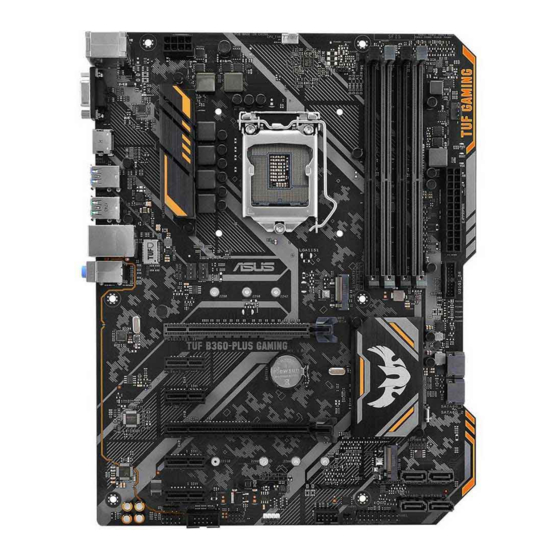
Failure to do so may cause severe damage to the motherboard, peripherals, or components. Motherboard overview Place this side towards the rear of the chassis Unplug the power cord before installing or removing the motherboard. Failure to do so can cause you physical injury and damage motherboard components. ASUS TUF B360-PLUS GAMING... - Page 12 1.2.1 Layout contents Connectors/Jumpers/Slots Page ATX power connectors (24-pin EATXPWR, 8-pin EATX12V) Intel LGA1151 CPU socket ® CPU, chassis, and AIO pump fan connectors (4-pin CPU_FAN, 4-pin CHA_FAN1~2, 4-pin AIO_PUMP FAN) DDR4 DIMM slots USB 3.1 Gen 1 connector (20-1 pin U31G1_56) M.2 sockets (M.2_1; M.2_2) Intel B360 Serial ATA 6.0 Gb/s connector (7-pin SATA6G_1~6) ® System panel connector (20-3 pin PANEL) Clear RTC RAM (2-pin CLRTC) 10. USB 2.0 connector (10-1 pin USB1114) 11. AURA RGB header (4-pin RGB_HEADER) 12. Serial port connector (10-1 pin COM) 13. Front panel audio connector (10-1 pin AAFP) 14. Digital audio connector (4-1 pin SPDIF_OUT) 15. PCI Express 3.0/2.0 x1 slots 16. PCI Express 3.0/2.0 x16 slots ATX power connectors (24-pin EATXPWR, 8-pin EATX12V) EATX12V Correctly orient the ATX power supply plugs into these connectors and push down firmly until the connectors...
- Page 13 DIMM sockets. For more details, refer to 1.4 System memory. USB 3.1 Gen 1 connector (20-1 pin U31G1_56) U31G1_56 Connect a USB 3.1 Gen 1 module to any of these PIN 1 USB3+5V connectors for additional USB 3.1 Gen 1 front or rear USB3+5V IntA_P1_SSRX- IntA_P2_SSRX- IntA_P1_SSRX+ panel ports. These connectors comply with USB 3.1 IntA_P2_SSRX+ IntA_P1_SSTX- Gen 1 specifications and provides faster data transfer IntA_P2_SSTX- IntA_P1_SSTX+ IntA_P2_SSTX+ IntA_P1_D- speeds of up to 5 Gbps, faster charging time for USB- IntA_P2_D- IntA_P1_D+ IntA_P2_D+ chargeable devices, optimized power efficiency, and backward compatibility with USB 2.0 ASUS TUF B360-PLUS GAMING...
- Page 14 M.2 sockets (M.2_1; M.2_2) M.2(SOCKET3) These sockets allow you to install M.2 (NGFF) SSD modules. • The M.2_1 socket supports M Key and 2242/2260/2280 storage devices (both SATA & PCIE x2 mode), and supports data transfer speed of up to 16Gb/s. • The M.2_2 socket supports M Key and 2242/2260/2280/22110 storage devices (PCIE x2 mode), and supports data transfer speed of up to 16Gb/s. • When a device in SATA mode is installed on the M.2_1 socket, SATA_2 port cannot be used. Intel B360 Serial ATA 6.0Gb/s connectors (7-pin ® SATA6G SATA6G_1-6) These connectors connect to Serial ATA 6.0 Gb/s hard RSATA_TXP RSATA_TXN disk drives via Serial ATA 6.0 Gb/s signal cables. RSATA_RXN RSATA_RXP System panel connector (20-3 pin PANEL) This connector supports several chassis-mounted functions.
- Page 15 This USB connectors comply with USB 2.0 specifications and supports up to 480Mbps connection speed. PIN 1 PIN 1 AURA RGB header (4-pin RGB_HEADER) These connectors are for RGB LED strips. Serial port connector (10-1 pin COM) This connector is for a serial (COM) port. Connect the serial port module cable to this connector, then install the module to a slot opening at the back of the system chassis. PIN 1 ASUS TUF B360-PLUS GAMING...
- Page 16 Front panel audio connector (10-1 pin AAFP) This connector is for a chassis-mounted front panel audio I/O module that supports HD Audio standard. Connect one end of the front panel audio I/O module AAFP cable to this connector. HD-audio-compliant pin definition Digital audio connector (4-1 pin SPDIF_OUT) This connector is for an additional Sony/Philips Digital Interface (S/PDIF) port. Connect the S/PDIF Out module cable to this connector, then install the module to a slot opening at the back of the system chassis. SPDIF_OUT We recommend that you connect a high-definition front panel audio module to this connector to avail of the motherboard’s high-definition audio capability.
- Page 17 Microphone port (pink). This port connects to a microphone. Refer to the audio configuration table for the function of the audio ports in 2, 4, 5.1, or 7.1-channel configuration. Audio 2, 4, 5.1, or 7.1-channel configuration Headset Port 4-channel 5.1-channel 7.1-channel 2-channel Light Blue (Rear panel) Line In Rear Speaker Out Rear Speaker Out Rear Speaker Out Lime (Rear panel) Line Out Front Speaker Out Front Speaker Out Front Speaker Out Pink (Rear panel) Mic In Mic In Bass/Center Bass/Center Lime (Front panel) Side Speaker Out ASUS TUF B360-PLUS GAMING...
- Page 18 To configure a 7.1-channel audio output: Use a chassis with HD audio module in the front panel to support a 7.1-channel audio output. USB 2.0 ports. These 4-pin Universal Serial Bus (USB) ports are for USB 2.0/1.1 devices. USB 3.1 Gen 2 Type-A ports. These 9-pin Universal Serial Bus 3.1 (USB 3.1) ports are for USB 3.1 Gen 2 devices. • Due to the limitation of USB 3.1 Gen 2 and USB 3.1 Gen 1 controller, USB 3.1 Gen 2 and USB 3.1 Gen 1 devices can only be used under Windows OS environment and after the USB 3.1 Gen 2 and USB 3.1 Gen 1 driver installation. • We strongly recommend that you connect USB 3.1 Gen 2 and USB 3.1 Gen 1 devices to USB 3.1 Gen 2 and USB 3.1 Gen 1 ports for faster and better performance from your USB 3.1 Gen 2 and USB 3.1 Gen 1 devices. USB 3.1 Gen 1 Type-A port. These 9-pin Universal Serial Bus (USB) ports are for USB 3.1 Gen 1 devices. • USB 3.1 Gen 1 devices can only be used for data storage. • We strongly recommend that you connect USB 3.1 Gen 1 devices to USB 3.1 Gen 1 ports for faster and better performance from your USB 3.1 Gen 1 devices. HDMI port. This port is for a High-Definition Multimedia Interface (HDMI) connector, and is HDCP compliant allowing playback of HD DVD, Blu-ray, and other protected content.
-
Page 19: Central Processing Unit (Cpu)
This motherboard comes with a surface mount LGA1151 socket designed for the 8th Generation Intel Core™ i7 / Core™ i5 / Core™ i3, ® Pentium and Celeron processors. ® ® Unplug all power cables before installing the CPU. • Ensure that you install the correct CPU designed for the LGA1151 socket only. DO NOT install a CPU designed for LGA1150, LGA1155 and LGA1156 sockets on the LGA1151 socket. • Upon purchase of the motherboard, ensure that the PnP cap is on the socket and the socket contacts are not bent. Contact your retailer immediately if the PnP cap is missing, or if you see any damage to the PnP cap/socket contacts/motherboard components. • Keep the cap after installing the motherboard. ASUS will process Return Merchandise Authorization (RMA) requests only if the motherboard comes with the cap on the LGA1151 socket. • The product warranty does not cover damage to the socket contacts resulting from incorrect CPU installation/removal, or misplacement/loss/incorrect removal of the PnP cap. Installing the CPU Apply the Thermal Interface Material to the CPU heatsink and CPU before you install the heatsink and fan if necessary. ASUS TUF B360-PLUS GAMING... -
Page 20: System Memory
Channel A DIMM_A1 & DIMM_A2 Channel B DIMM_B1 & DIMM_B2 • You may install varying memory sizes in Channel A and Channel B. The system maps the total size of the lower-sized channel for the dual-channel configuration. Any excess memory from the higher-sized channel is then mapped for single-channel operation. • Always install DIMMs with the same CAS latency. For optimal compatibility, we recommend that you install memory modules of the same version or date code (D/C) from the same vendor. Check with the retailer to get the correct memory modules. • According to Intel CPU spec, DIMM voltage below 1.35V is recommended to protect ® the CPU. • Due to Intel chipset limitation, DDR4 2666MHz and higher memory modules will run ® at max. 2666MHz on Intel 8th Gen. 6-core or higher processors. ® • The default memory operation frequency is dependent on its Serial Presence Detect (SPD), which is the standard way of accessing information from a memory module. Under the default state, some memory modules for overclocking may operate at a lower frequency than the vendor-marked value. • For system stability, use a more efficient memory cooling system to support a full memory load (4 DIMMs). • Refer to www.asus.com for the latest Memory QVL (Qualified Vendors List) 1-10 Chapter 1: Product Introduction... - Page 21 Installing a DIMM To remove a DIMM ASUS TUF B360-PLUS GAMING 1-11...
- Page 22 1-12 Chapter 1: Product Introduction...
-
Page 23: Chapter 2: Bios Information
Managing and updating your BIOS Save a copy of the original motherboard BIOS file to a USB flash disk in case you need to restore the BIOS in the future. Copy the original motherboard BIOS using the ASUS Update utility. - Page 24 2.1.2 ASUS EZ Flash 3 The ASUS EZ Flash 3 allows you to download and update to the latest BIOS through the Internet without having to use a bootable floppy disk or an OS‑based utility. • Ensure to load the BIOS default settings to ensure system compatibility and stability.
- Page 25 2.1.3 ASUS CrashFree BIOS 3 utility The ASUS CrashFree BIOS 3 is an auto recovery tool that allows you to restore the BIOS file when it fails or gets corrupted during the updating process. You can restore a corrupted BIOS file using the motherboard support DVD or a USB flash drive that contains the updated BIOS file.
- Page 26 ENTER to select boot device ESC to boot using defaults P2: ST3808110AS (76319MB) aigo miniking (250MB) UEFI: (FAT) ASUS DRW-2014L1T(4458MB) P1: ASUS DRW-2014L1T(4458MB) UEFI: (FAT) aigo miniking (250MB) Enter Setup When the booting message appears, press <Enter> within five (5) seconds to enter FreeDOS prompt.
- Page 27 DO NOT shut down or reset the system while updating the BIOS to prevent system boot failure. Ensure to load the BIOS default settings to ensure system compatibility and stability. Select the Load Optimized Defaults item under the Exit BIOS menu. See section 2.3 Exit Menu for details. ASUS TUF B360-PLUS GAMING 2‑5...
-
Page 28: Bios Setup Program
The BIOS setup screens shown in this section are for reference purposes only, and may not exactly match what you see on your screen. • Visit the ASUS website at www.asus.com to download the latest BIOS file for this motherboard. •... - Page 29 Click to go to Advanced mode Loads optimized Search on the FAQ default settings Click to display boot devices Selects the boot device priority The boot device options vary depending on the devices you installed to the system. ASUS TUF B360-PLUS GAMING 2‑7...
- Page 30 2.2.2 Advanced Mode The Advanced Mode provides advanced options for experienced end‑users to configure the BIOS settings. The figure below shows an example of the Advanced Mode. Refer to the following sections for the detailed configurations. To access the EZ Mode, click EzMode(F7) or press <F7>. Search(F9) Configuration fields Scroll bar...
- Page 31 AURA (F4) This button allows you to turn the RGB LED lighting or functional LED on or off. [ON] All AURA effects will be enabled. (Default mode) [OFF] All AURA effects will be disabled. ASUS TUF B360-PLUS GAMING...
- Page 32 Move your mouse over this button to show a QR code, scan this QR code on your mobile device to connect to the BIOS FAQ web page of the ASUS support website. You can also scan the following QR code:...
-
Page 33: Exit Menu
<Esc>, a confirmation window appears. Select OK to discard changes and exit. Launch EFI Shell from USB drives This option allows you to attempt to launch the EFI Shell application (shellx64.efi) from one of the available USB devices. ASUS TUF B360-PLUS GAMING 2-11... - Page 34 2-12 Chapter 2: BIOS Information...
-
Page 35: Appendix
Consult the dealer or an experienced radio/TV technician for help. The use of shielded cables for connection of the monitor to the graphics card is required to assure compliance with FCC regulations. Changes or modifications to this unit not expressly approved by the party responsible for compliance could void the user’s authority to operate this equipment. ASUS TUF B360-PLUS GAMING... - Page 36 Compliance Statement of Innovation, Science and Economic Development Canada (ISED) This device complies with Innovation, Science and Economic Development Canada licence exempt RSS standard(s). Operation is subject to the following two conditions: (1) this device may not cause interference, and (2) this device must accept any interference, including interference that may cause undesired operation of the device.
- Page 37 ASUS Recycling/Takeback Services ASUS recycling and takeback programs come from our commitment to the highest standards for protecting our environment. We believe in providing solutions for you to be able to responsibly recycle our products, batteries, other components as well as the packaging materials.
- Page 38 доступний на: www.asus.com/support Cijeli tekst EU izjave o sukladnosti dostupan je na: www.asus.com/support Türkçe AsusTek Computer Inc., bu aygıtın temel gereksinimlerle ve ilişkili Čeština Společnost ASUSTeK Computer Inc. tímto prohlašuje, že toto Yönergelerin diğer ilgili koşullarıyla uyumlu olduğunu beyan eder.
- Page 39 +1-510-608-4555 Web site https://www.asus.com/us/ Technical Support Support fax +1-812-284-0883 Telephone +1-812-282-2787 Online support https://www.asus.com/support/Product/ContactUs/ Services/questionform/?lang=en-us ASUS COMPUTER GmbH (Germany and Austria) Address Harkort Str. 21-23, 40880 Ratingen, Germany +49-2102-959931 Web site https://www.asus.com/de/ Technical Support Telephone +49-2102-5789555 Support Fax +49-2102-959911 Online support https://www.asus.com/support/Product/ContactUs/...
- Page 40 Product Name : Motherboard Model Number : TUF H370-PRO GAMING, TUF B360-PRO GAMING, TUF B360-PLUS GAMING Conforms to the following specifications: FCC Part 15, Subpart B, Unintentional Radiators Supplementary Information: This device complies with part 15 of the FCC Rules. Operation is subject to the...
Need help?
Do you have a question about the TUF B360-PLUS GAMING and is the answer not in the manual?
Questions and answers