Table of Contents

Related Manuals for Fuji Electric FCX-CII SERIES


Summary of Contents for Fuji Electric FCX-CII SERIES
- Page 1 Instruction Manual FCX-CII SERIES TRANSMITTERS Differentiel pressure Transmitter (FKK ...4) Pressure Transmitter (FKP...4) Pressure Transmitter with remote seal (FKP...E) Absolute Pressure Transmitter (FKH...E) Fuji Electric France S.A. INF-TN3FCXC2b-E...
-
Page 2: Introduction
INTRODUCTION INTRODUCTION Thank you very much for your purchase of the Fuji FCX-CII Series Transmitter. This instruction manual covers the FCX-CII series transmitter and contains information about the installation, piping, wiring, operation and maintenance of the FCX-CII series (FKK...4 • FKP...4 • FKP...E). -
Page 3: Caution On Safety
CAUTION ON SAFETY First of all, read this “Caution on Safety” to ensure correct operation of the transmitter. • The cautionary descriptions listed here contain important information about safety, so they should be observed without fail. Those safety precautions are classified into ranks “DANGER” and “CAUTION”. Wrong handling may cause a dangerous situation, in which there is a DANGER risk of death or heavy injury. - Page 4 Wiring DANGER • On explosion-proof type transmitter, its wiring work must be performed according to the required laws and regulations. Incorrect wiring may cause explosion, fire or other serious accidents. CAUTION • Before making wiring work, be sure to turn OFF the main power to prevent electric shocks. •...
-
Page 5: Caution On Use
CAUTION ON USE Be sure to observe the following Instructions Storage for a long period Store the transmitter in a dry room at normal temperature and humidity. Keep protection caps in place at the conduit connection and process connection. For installation, select an appropriate place Site at location with minimal vibration, dust and corrosive gas At a place allowing an adequate space for checkup Site at location large enough to allow maintenance and checking. -
Page 6: Table Of Contents
CONTENTS INTRODUCTION ..........................i CAUTION ON SAFETY ........................ii CAUTION ON USE ..........................iv CONFIRMATION OF YOUR SPECIFICATION ................iv OUTLINE ............................1 OPERATING PARTS AND THEIR FUNCTIONS ..............2 OPERATION AND SHUTDOWN ....................4 3.1 Preparation for operation ......................4 3.2 Operation ............................ -
Page 7: Outline
OUTLINE The FCX-CII series transmitter detects the differential pressure or pressure of various fluids, converts it into a current signal of 4 to 20 mA DC and transmits it. All the adjustment functions are incorporated in the transmission unit for making adjustments easily and exactly. -
Page 8: Operating Parts And Their Functions
OPERATING PARTS AND THEIR FUNCTIONS FCX-CII Series transmitter Transmission unit Process connection Detecting unit Analog indicator Transmission unit connector Digital indicator connector Vent/drain Conduit plug connection Zero/span Indicator adjustment (Digital) (Analog) Terminal unit screw Terminal unit DISP ZERO Description of FCX-CII Series transmitter Part name Description Detecting unit... - Page 9 Mode indicating function of digital indicator DISP ZERO Mode indication Mode When indicated When not indicated % output Actual scale ZERO External zero adjustment possible External zero adjustment impossible DISP Digital indicator display Digital indicator proportional display output Proportional output Fixed current mode Measurement mode Sampling status (Flicker)
-
Page 10: Operation And Shutdown
OPERATION AND SHUTDOWN 3.1 Preparation for operation Before operating the transmitter, be sure to perform the following checks and procedures. Note that adjustment is required in a non-hazardous area for zero point check of intrinsically safe explosionproof and flameproof transmitters, do not open terminal cover and do not use HHC. Use the transmitter indicator and the external adjustment screw. - Page 11 Zero point check Turn on the power to the transmitter. Check the output signal of the transmitter by connecting a DC ammeter across CK+ and CK– of the terminal block. After ten minutes or longer, adjust the transmitter output current to 4 mA (zero adjustment). (See below.) (1) Zero adjustment Zero point of the transmitter is adjustable by the zero screw on the electronics housing with...
-
Page 12: Operation
3.2 Operation (1) Operation of pressure transmitter Open the valve slowly to apply a pressure. When a pressure is applied, the transmitter is set in the operating status. Open (2) Operation of differential pressure transmitter Set the operating status by manipulating the manifold valve. Stop valve on the low pressure side... -
Page 13: Shutdown
Open Finally, open the stop valve on the low pressure side slowly. Check of operating status Use a field indicator, receiving instrument or HHC to check the operating status. 3.3 Shutdown (1) Shutdown of pressure transmitter Close the valve slowly to stop applying a pressure. The transmitter is set in the measurement stop status. - Page 14 (2) Shutdown of differential pressure transmitter Set the shutdown status by manipulating the manifold valve. Turn off power supply. Close the stop valve on the high pressure side (H side) slowly. Close Open Open the equalizing valve. Close Close the stop valve on the low pressure side (L side) slowly.
-
Page 15: Adjustment Of Smart Line
ADJUSTMENT OF SMART TYPE To operate the FCX-CII series transmitter, the HHC is used for each adjustment. 4.1 Adjustment with HHC Startup and usage of the Hand Held Communicator (HHC) are detailed in the instruction manual for HHC. Please refer to this manual before commencing adjustment. After adjustment of the transmitter, it should be kept energized for about 10 sec- Important onds to write the adjustment results into memory. - Page 16 4.1.2 Outline of HHC operation The following shows the flow of the key, explained for FXW Version 6.0 (FXW 1- A3). FXW prior to Version 6.0 are not available of operation of FCX-CII series transmitter. In this case, the user is requested to contract our office for ROM version up. Referential Display symbol Key symbol...
- Page 17 4.1.3 Operating procedure In case of a flameproof transmitter, never connect the HHC to the terminal block of transmitter in hazardous area installations. ° TAG N PUSH MENU KEY To set the TAG N°. of each field de- vice, use the procedures shown in the following diagram.
- Page 18 TYPE Menu 1 : TAG N° Type of field device is displayed and changed (ex. of differential pressure transmitter). • After TAG N°. is displayed, press the <INC> key to display TYPE 2-1: TYPE CHANGE TYPE CHNG FKCXXXXX-XXXXX FKCXXXXX-XXXXX image. <...
- Page 19 Industrial value unit Available unit for FCX-C2 Menu N°3 : SERIAL N° mmH O cmH O mH O g/cm UNIT kg/cm < INC > < CHNG > CHNG 4-1: UNIT CHANGE mbar (NEXT MPa) < INC > < ENT > <...
- Page 20 Range limit Menu N°4 : UNIT Indicates the maximum measuring range of this transmitter. 5: RANGE LIMIT × × × Range change (LRV, URV) < INC > LRV: Lower range value (0% point) CHNG URV: Upper range value (100% RANGE 6-1: RANGE CHANGE point)
- Page 21 Damping adjustment When process input changes exces- Menu N°6 : RANGE sively, an appropriate damping time constant should be set. CHNG Input time constant value under DAMPING 7-1: DAMP CHANGE 0.3SEC 0.3SEC display 2 , time constant can be < INC > <...
-
Page 22: Output Mode
Output mode The output mode is used to select the LIN/ proportional mode (proportional to in- (DP) GP, AP, LL (Liquid Level) OUTPUT MODE : OUTPUT MODE put differential pressure) or square XMTR:DP XMTR:GP OUT=LIN OUT=LIN root extraction mode (proportinal to <... - Page 23 Burnout direction Used for selecting output at occur- rence of a fault in the detecting unit. CHNG 9:BURNOUT 9-1: BURNOUT Burnout direction is selectable un- NOT USED < 1 > NOT USED (HOLD) < 2 > OVER SCALE der display 2 . <...
- Page 24 Zero/span adjustment < Zero adjustment > Zero and span are adjustable by apply- CALIBRATE A-1: CALIBRATE ××× ×× ing an actual pressure. ××× × < INC > < LRV > < URV > < ENT > < CL > When pressing <LRV> under display 1 the screen for zero adjustment 2 appears, and that for span adjustment 5 A-1:...
- Page 25 Calibration of output circuit (D/A) The output circuit (D/A) should be calibrated by the following procedure OUTPUT ADJ when necessary. < INC > < CHANGE > CHNG Make calibration wiring transmitter according to "Calibration" in Appen- B-1: OUTPUT SET dix A2, and calibrate the output cir- cuit with the HHC using the follow- <...
- Page 26 Indication of measured data The measured value can be indi- DATA cated. more information about C-1: DATA DATA operating procedure, refer to the in- XXX. X %FLOW XXXXX kPa struction manual of HHC. < INC > < ENT > < CHANGE > < CL > CHNG "FLOW"...
- Page 27 [Contents of message] As a result of self-diagnosis, the message below is appeared on the LCD display of HHC, when there are trouble in the transmitter. For each error, its cause and remedy are suggested. Indication on Message Cause Remedy digital indicator CELL FAULT (C1) FL-1...
- Page 28 Lock of adjustment function CHNG The zero adjustment function can be XMTR EXT. SW F-1: XMTR EXT. SW < 1 > INHIBIT locked by the transmitter adjust ENABLE < 2 > ENABLE < INC > < CHANGE > < 1 > < 2 > < CL > screw.
- Page 29 Indication of digital indicator ±YYYYYY=XMTR DISPLAY G : XMTR DISPLAY G : XMTR DISPLAY For digital indicator, either % dis- at 4mA % DISPLAY ±YYYYYY/±ZZZZZZ ±ZZZZZZ=XMTR DISPLAY X.XX-XXX.XX%YYYY UUUUUUU play or actual-scale display is se- Note 1 at 20mA < INC > < CHANGE > <...
- Page 30 When setting the actual-scale display, first select <2> ACTUAL DISP in 3 . G-2 : DISP. CHANGE Next, after setting the actual-scale LRV: 4mA=±YYYYYY Already set value URV: 20mA=±ZZZZZZ of transmitter display value ( 11 to 14 ), perform the <...
- Page 31 When setting of % Flow in %display or Flow unit in actual scale display, low OUT=SQR at Menu No.8 flow cut point and low flow cut mode OUT=LIN at Menu No.8 are displayed ( 22 or 23 ). G-8 : LOW CUT G-8 : LOW CUT POINT=XX.XX%FLOW POINT=XX.XX%FLOW...
- Page 32 Programmable linearization function User can set output compensation LINEARIZE against input using INVALID compensation points, (X ), (X < INC > < CHNG > )…(X ). Each compensation CHNG value between (Xn, Yn) and (Xn+1, Yn+1) is connected by first order CHNG H-1: LINEARIZE...
- Page 33 Change of compensated point for CV H-4: LINEARIZE H-4: LINEARIZE CV1 XXX.XX% CV3 XXX.XX% < INC> < CNG/ENT/CL > < INC> < CNG/ENT/CL > CV14 Next parameter H-4: LINEARIZE H-4: LINEARIZE Important CV2 XXX.XX% CV14 XXX.XX% < INC> < CNG/ENT/CL > <...
- Page 34 Rerange (Set LRV/URV calibration) RERANGE (application to level measurement) at < INC > < CHNG > CHNG change of level (LRV/URV) I-1: RERANGE Functions of RERANGE can be made with FXW Version 6.0 or upward. < LRV > < URV > < CL > When the lower range value (LRV) and I-2: RERANGE...
-
Page 35: Zero Adjustment By The External Screw
4.2 Zero Adjustment by the external screw Zero point of the transmitter is adjustable by the outside screw with the mode setting switch in the housing set at zero position. The figure shown below is an example of “Mode setting switch”... -
Page 36: Span Adjustment By The External Screw
4.3 Span adjustment by the external screw The measuring range for each transmitter is determinated according to its type. Span is changed by the outside screw with the mode setting switch in the housing set at span position. The figure shown below is an example of “Mode setting switch” is attached. (1) Set the mode setting switch to span position. -
Page 37: Local Adjustment Unit With Lcd Display
4.4 Local adjustment unit with LCD display 1. Outline When local adjustment unit with LCD display (Parts number is *ZZPFCX4-A055) is installed in the FCX-CII transmitter, some functions are available without HHC (Hand Held Communicator). Name of each part in local adjustment unit with LCD display and their functions are indicated below. - Page 38 2.Selection of transmitter adjustment method LOCAL/COMM. Changing switch decides the method of FCX-CII transmitter adjustment. If switch is set to “COMM.” side, adjustment of transmitter is carried out by HHC. This method is explained in instruction manual. If switch is set to “LOCAL” side, adjustment of transmitter is carried out by Mode setting switch and Damping setting switch.
- Page 39 3.2 Span adjustment (Change Upper Range Value) The measuring range for each transmitter is determined according to its type. The span is changed by the external adj. screw when the mode setting switch is set at “1” or ”6" position. (1) Set the mode setting switch to “1”...
-
Page 40: Maintenance
MAINTENANCE 5.1 Periodic inspection In order to ensure the measurement accuracy and long life of the transmitter, it is essential to inspect the transmitter periodically according to the operating conditions. Visual inspection Visually inspect each part of the transmitter for damage, corrosion, etc. If you detect any material which may cause corrosion, it should be cleaned off. -
Page 41: Troubleshooting
5.2 Troubleshooting If an abnormality occurred in the process or transmitter, action should be taken with reference to the table below. Symptom Cause Remedy (1) The manifold valve does Repair the valve so that it opens/closes normally. not open/close normally. Repair a leak. -
Page 42: Replacement Of Parts
5.3 Replacement of parts If the transmitter requires a replacement part, drain process fluid from the transmitter, disconnect it from the process and carry out replacement in an instrument room. When removing an explosion-proof transmitter, turn OFF the main power, then dis- connect the piping and wiring. - Page 43 Replacement of detecting unit Transmission unit Detecting unit Flexible printed circuit board Hexagonal socket bolt Replacing procedure (1) Remove the electronics unit according to “Replacement of electronics unit”. (2) Remove the hex. socket bolts from the electronic housing. Pull the electronics housing straight forward and away from the detecting unit. (3) Replace the detecting unit with a new one of the same type.
- Page 44 Replacement of the internal parts of detecting unit In case of differential transmitter (code symbol : FKK/FDK) : Seal diaphragm O-ring Measurement chamber detecting cover Seal tape Bolt Seal tape Replacing procedure (1) Remove four hexagon socket head bolts with a torque wrench, etc.. (2) Disassembly gives access to the casing covers, O-rings, hexagon socket head bolts and nuts.
- Page 45 Replacement of field indicator 1. Replacement of analog indicator Analog indicator Transmitter cover Replacing procedure (1) Detach the transmitter cover. (2) Remove the analog indicator. (3) Pull out the connector extending from the analog indicator. (4) Connect the connector of a new analog indicator to the electronics section. (See the figure below.) (5) Then, mount the analog indicator at the electronics section.
- Page 46 2. Replacement of digital indicator Digital indicator Transmitter cover Digital indicator mounting board Replacing procedure (1) Detach the transmitter cover. (2) Remove two fixing screws which fasten the digital indicator and separate the indicator. (3) Pull out the leading end of the flexible PC board extending from the digital indicator after raising the slider (white knob) in the electronics section.
-
Page 47: Adjustment After Replacement Unit
5.4 Adjustment after replacement of unit Adjustment After completion of the assembly work mentioned above, use the following procedures for adjust- ment and setting. Adjustment should be performed using the HHC. (1) After replacement of electronics unit (including replacement of internal parts) S tep Adjustment item Relevant page... -
Page 48: Installation And Piping
INSTALLATION AND PIPING 6.1 Installation After unpacking, check the delivered items. This transmitter can be mounted on a pipe or on a wall. Note that the bolts (M8) for wall mounting should be supplied by the customer. • The transmitter is heavy. Be careful when handling it. •... - Page 49 Change of field indicator position Avoid the following procedure in an explosionproof area. CAUTION It is sometimes preferable to mount the indicator on the terminal block side due to installation location. In such a case, the following mounting procedure should be followed for analog indicator. Digital indicator cannot be mounted on the terminal block side.
- Page 50 Change of transmission unit position Avoid the following procedure in an explosionproof area. CAUTION Wiring is sometimes difficult depending on the installation loca- tion. In such a case, it is convenient to carry out the following. Before turning the transmission unit, remove the electronics unit.
- Page 51 Change of vent/drain plug position Hold the hexagonal area of the vent/drain plug Process connection with a wrench and remove it by turning slowly. Peel the existing seal tape and wind a new seal type. Then, screw the vent/drain plug into the process connection for changing.
-
Page 52: Piping
6.2 Piping It is generally recognized that there are appropriate positioning relationship between the transmitter and main process piping for accurate measurement to avoid harmful gas or liquid accumulation. General recognizations are; 1- Mount transmitter below main process piping for liquid or steam measurement. 2- Mount transmitter above main process piping for gas measurement. - Page 53 Typical examples of piping Manifold valve Flow measurement (in case of gas) Impulse pipe Stop valve Place the transmitter above the differential pres- sure source. Process pipe Differencial pressure source (orifice) Differencial pressure source (orifice) Flow measurement (in case of liquid) Process pipe Place the transmitter below the differential pres- Stop valve...
- Page 54 (1) Protection is required to prevent dust from entering through the atmospheric Important air inlet after installation of the manifold valve. (2) If process pressure range is narrow (below 10kPa (1000mmH O)), the follow- ing should be considered. • Pressure variation due to wind around atmospheric air inlet •...
- Page 55 Cautions on impulse piping • For liquid, the impulse pipes should have an upward slope of 1/10 or more between the process connection and the transmitter to prevent accumulation of gas, etc. in the detect- ing unit. • For gas, the impulse pipes should have a downward slope of 1/10 or more between the process connection and transmitter to prevent accumulation of moisture, etc.
- Page 56 6.2.2 Piping of pressure transmitter type : FKP Removal of protective cap The process connection port of the transmitter is fitted with a protective cap. Before piping, remove the cap carefully. When removing the cap, carefully protect the threaded portion and sealing face from damage.
- Page 57 Typical examples of piping Gas measurement Manual valve Place the transmitter above the pressure source. Impulse pipe Stop valve Pressure source Process pipe Liquid measurement Process pipe Place the transmitter below the pressure source. Pressure source Make piping so that gas in the process pipe is not Stop valve delivered to the transmitter, and incorporate gas reservoirs as required.
- Page 58 6.2.3 Piping of level transmitter type : FKP for open tank Seal on mounting flange face When mounting the flange on the pressure side, a gasket should be inserted as follows. Transmitter flange Process side flange Gasket On the projection type, be sure to use a gasket with an internal diameter larger Important than the flange to prevent the gasket form touching the seal diaphragm.
- Page 59 Caution of installation • Restriction on H Liquid level is not proportional to the transmitter output at some points inside the seal diaphragm. Therefore, H should be set higher than the value shown in the table below. • In order to prevent vibration, the transmitter body should be installed at a vibration-free place.
-
Page 60: Wiring
WIRING Cautions on wiring (1) Application of a voltage exceeding 60 V DC or 40 V AC (exceeding 32 V DC or 23 V AC when arrester equipped) between “+” and “–” terminals may result in damage to the transmitter. (2) Use a shielded cable for the transmission line where possible. - Page 61 Terminal block connection diagram Tighten the terminal screws (M4 x10) to a torque of approximately 1.5 N•m (15 kgf•cm) <11ft- lb> so that the wires will not loosen. After connection, fasten the cover until it does not turn. Terminal 10.5 ~ 45 V DC (Analog type) 16.1 ~ 45 V DC (Smart type) Conveter Output DC4 ~ 20mA...
-
Page 62: Power Voltage And Load Resistance
Things convenient to know beforehand When using conduit connection at the top For wiring from the top conduit connection, use the following procedure. Remove the screw plug of the top conduit connection. Screw the removed screw plug into the bottom conduit connection. Insert the cable from the top and connect it. -
Page 63: Grounding
7.3 Grounding The transmitter must be grounded. Otherwise, it may cause electric shocks or incorrect operation. CAUTION Grounding terminals are provided at two places (at the inside of terminal box and on the side of conduit connection). By any of the methods given below, ground the transmitter in compliance with the relevant stipu- lation in the standard on explosionproof installation (for example, grounding resistance 100 Ω... -
Page 64: Spare Parts
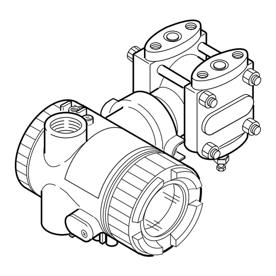
SPARE PARTS This diagram shows main parts of the differential pressure transmitter, pressure transmitter. For details, contact our office. - Page 65 Parts No. Part Name Q’ty Material Remarks * ZZPFCX4-A010 Cover Aluminium alloy Blue ADC12 * ZZPFCX4-A020 Cover Aluminium alloy Blue ADC12 * ZZPFCX4-A030 Cover ass'y Aluminium alloy With indicator ADC12 * ZZPFCX4-A050 Indicator Analog, 0 to 100% linear * ZZPFCX4-A051 Indicator Analog, 0 to 100% square-root * ZZPFCX4-A052...
- Page 66 Parts No. Part Name Q’ty Material Remarks B-1~5 –––––––– Detecting unit Contact our office for inquiry (Differential pressure and Flow) * ZZPFCX4-B080 O-ring Viton Minimum order q’ty 10 pcs. * ZZPFCX4-B081 Square section gasket Teflon 4th digit of type code * ZZPFCX4-B091 Cover...
-
Page 67: A1 Built-In Arrester
BUILT-IN ARRESTER General An arrester is used to protect a transmitter or receiver from an abnormal voltage such as lightning surges induced into signal lines. A built-in type arrester is mounted behind the terminal unit. A nameplate marked “with arrester” is attached to the terminal unit of transmitter with a built-in arrester. - Page 68 Maintenance ♦ Check of arrester • Measure output current from the transmitter check terminals and output current to flow into transmitter (see figures below). When current is measured with an ammeter connected to CK+ and CK- terminals, the internal resistance of the ammeter should be 12Ω or less. •...
-
Page 69: A2 Calibration
CALIBRATION Preparation for calibration The transmitter should be calibrated in a calibration room. For calibration of each transmitter, the following devices are required. o Pressure source and pressure measuring equipment (should have as high an accuracy as pos- sible) * Measurable ranges are listed in the table below. o Power supply : DC power supply (24 V DC) or Fuji Electric FC series power supply unit (type PXJ or PXL) o Load resistor : Standard resistor 250 Ω... - Page 70 Calibration procedure (1) Make wiring according to the diagram below. Connect DC power supply (power source), digital voltmeter (measuring device), standard resistance and HHC (Hand Held Communicator): When current is measured with an ammeter connected to CK+ and CK- terminals, the internal resistance of the ammeter should be 12Ω...
-
Page 71: A3 Parameter Setting Prior To Delivery
PARAMETER SETTING PRIOR TO DELIVERY The damping value (time constant), function of zero/span adjust screw, output current mode, indicator scale, cut point, mode below cut point and burnout, have been set prior to delivery as shown in the following. Item Contents of parameter No Damping Damping value... -
Page 72: A4 Hazardous Location Installation Information
HAZARDOUS LOCATION INSTALLATION INFORMATION This appendix contains one table and four drawings that present installation instruction for the FCX-A/C Series Transmitter in a hazardous location. Refer to these figures when installing or servicing a transmitter mounted in a hazardous location. When installed the apparatus MUST be provided with a voltage limiting device which will prevent the rated voltage of 45V being exceeded. - Page 74 Fuji Electric France S.A. 46, Rue Georges Besse - Z I du Brézet 63 039 Clermont-Ferrand cedex 2 — FRANCE France : Tél. 04 73 98 26 98 - Fax 04 73 98 26 99 International : Tél. (33) 4 7398 2698 - Fax. (33) 4 7398 2699 E-mail : sales.dpt@fujielectric.fr Fuji Electric can accept no responsibility for possible errors in catalogues, brochures and other printed material.
Need help?
Do you have a question about the FCX-CII SERIES and is the answer not in the manual?
Questions and answers