
Related Manuals for Fuji Electric FCX-AII-VG Series


Summary of Contents for Fuji Electric FCX-AII-VG Series
- Page 1 INSTRUCTIONS MANUAL "FCX-AII-VG" serie transmitters with safety function Type : FKC...G FKG...G, FKP...G FKA...G, FKH...G FKE...G FKD, FKB, FKM...G FKP, FKH...G Fuji Electric France S.A.S. TN5FCXA2VGa-E May 2019 DATE...
- Page 3 Thank you very much for your purchase of the FCX-AII-VG serie transmitters with safety function. First read this instruction manual carefully until an adequate understanding is required, and then proceed to installation, operation and maintenance of the FCX-AII Serie transmitters with safety function.
- Page 4 CAUTION : Rotating the upper assembly part : The upper assembly (housing and electronic unit) can be rotated by 90° left or right just by remo- ving the 3 hexagonal screws. If the assembly parts must be turned over than 90°, or if the position is already amended since the delevery by Fuji, it's necessary to remove the electronic unit from the housing and disconnect the flatcable from the electronic measuring...
-
Page 5: Introduction
The specifications of the transmitter will be changed without prior notice for further product improvement. Modification of the transmitter without permission is strictly prohibited. Fuji Electric will not bear any responsibility for a trouble caused by such a modification. This instruction manual should be kept by a person who is actually using the transmitter. -
Page 6: Electromagnetic Compatibility
ELECTROMAGNETIC COMPATIBILITY ELECTROMAGNETIC COMPATIBILITY All models FCX-AII series transmitters type FCX-AII VG are in accordance with :. The harmonized standards : • EN 61326-1 (Electrical equipment for measurement, control and laboratory use - EMC requirements) • EN 61326-2-3 (Part 2-3 : Particular requirements - Test configuration, operational conditions and performance criteria for transducers with integrated or remote signal conditioning). -
Page 7: Classification Of Safety Instructions
CLASSIFICATION OF SAFETY INSTRUCTIONS First of all, read carrefully the “Safety instructions” for your own safety and for cor- rect use of the transmitter. • The risks related to a non-respect of the instructions are priorized as follow : Risk of death or sever injury if the safety instructions are not fol- DANGER lowed. -
Page 8: Important Recommendations
IMPORTANT RECOMMENDATIONS Storage for a long period If the Pressure transmitter is not mounted rapidly on site after the delivery, please store the transmitter in a dry room at normal temperature and humidity (25°c and 60% RH). Keep it on the originaly packaging if possible. For installation, select an appropriate place Site at location with minimal vibration, dust and corrosive gas Accessibility... -
Page 9: Table Of Contents
CONTENTS INTRODUCTION ...........................2 ELECTROMAGNETIC COMPATIBILITY .....................3 CLASSIFICATION OF SAFETY INSTRUCTIONS ................4 IMPORTANT RECOMMENDATIONS ....................5 1. OUTLINE ............................7 2. OPERATING PARTS AND THEIR FUNCTIONS ................8 3. INSTALLATION AND PIPING ......................10 3.1 Installation ......................... 11 3.2 Piping ..........................15 3.2.1 Piping of differential pressure and flow tranmitters ............15 3.2.2 Piping of gauge and absolute pressure tranmitters ...........19 3.2.3 Piping of direct mount : absolute and gauge pressure tranmitters ......21 3.2.4 Piping of level transmitter ..................23... -
Page 10: Outline
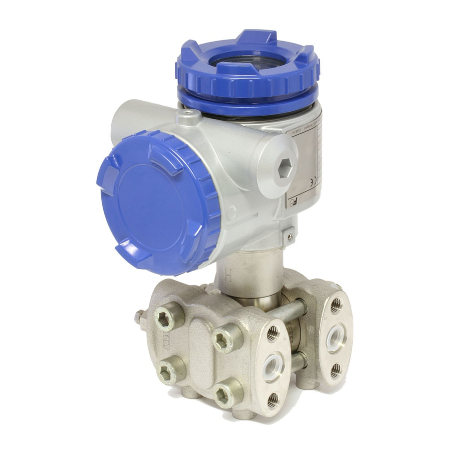
OUTLINE The FCX-AII VG series transmitter accurately measures a differential pressure, level of liquid, gauge pressure or absolute pressure, and transmits a proportional current signal of 4 to 20mA DC. This transmitter can be used for flowrate, level, density measurement and other application using differential pressure measurement. -
Page 11: Operating Parts And Their Functions
OPERATING PARTS AND THEIR FUNCTIONS Amplifier unit Terminal unit Analog indicator connector LCD unit connector Zero/Span adjustment Process Amplifer connection selector switch unit Detecting Indicator unit (Local configurator unit (Analog) with LCD display) DISP SPAN Vent/drain ZERO plug Adjusting screw MODE Description of FCX-AII VG serie transmitters Part name... - Page 12 Modes of the local configurator unit with LCD display and functions of the 3 push button key switches Minus key Plus key DISP SPAN ZERO Mode key MODE Normal mode (normal mode for indicating a measured value) Blicking Measurement (Transmitter value is running) SPAN...
-
Page 13: Installation And Piping
200 bar 500 bar Refer to "technical datasheets" about details of process temperature limits of the transmitters. For specific transmitters with static pressure > 420 bar, ask Fuji Electric. Protect the transmitter with a security device when the existing application INDICATION conditions require it. -
Page 14: Installation
3.1 Installation During the unpacking of the transmitter, check the conformity of the transmitter and all the ac- cessories. Before installation, the customer must check the compatibility of the wetted parts for the ap- plication. The possibility of a modification of the process has to be taken in account by the customer. - Page 15 FDP and FDH models Transmitter Bracket Plain washer Spring washer Mounting bolt (M4×10) Adaptor (Option) Process mounting • Pipe mounting FKC, FKG and FKA models FKD, FKB and FKM models U-Bolt • Wall mounting Fasten the transmitter to the wall with M8 bolts. FKP and FKH models (1) Fasten the transmitter to a vertical or horizontal pipe using the supplied U-bolt (Tightening torque approximately 15 Nm (1.5 kgf m)<11 ft-lb>).
- Page 16 Change of electronics housing position DANGER Avoid the following procedure in an explosionproof area. The wiring or the access can be difficult according to the position of the transmitter. The elec- tronics housing position can be modified by turning it by steps of 90 or 180 degrees. The electronics housing is fixed by hexagonal socket bolts (M6 x 12).
- Page 17 Check space Ensure a space of about 500mm against the cover in order to facilitate the maintenance. Change of vent/drain plug position Unscrew slowly the hexagon part of vent/drain plug with an allen key. Put a new seal tape (4 to 8 rounds) and mount the vent/drain plugs in the position you want applying the tightening torque : Tightening torque : 25Nm (2.5kgf m) <18ft lb>...
-
Page 18: Piping
3.2 Process piping The piping connection must respect some rules to have an accurate measurement : General recognitions are : 1) Transmitter must be mounted below the process piping for liquid and steam measurement. 2) Transmitter must be mounted above the process piping for gaz measurement. Main valve or manifold used for piping should be selected with the maxi- ATTENTION mum pressure of the process taken into account (piping parts such as... - Page 19 Position of process connection The position of the process connection is determined by the relationship between the condi- tion, characteristics and measuring point of the process fluid. Follow the process position according to the process : Gas measurement Liquid measurement Steam measurement Upper Upper...
- Page 20 4- Pressure measurement for liquid Pressure tap The transmitter must be below the process pipe. Process pipe Isolating valve Impulse pipe Atmospheric air inlet Manifold (1) During valves and manifold installation, please make sur that no dust ATTENTION enter through the atmospheric air inlet. (2) If pressure measurement is low (below 10kPa (1000mmH O), the fol- lowing should be considered.
- Page 21 (2) Reference column empty For an open tank, leave the low pressure side of transmitter open to atmosphere. Level calculation formula Max. liquid LRV: ρH ρ level URV: ρH + ρ Min. liquid level Atmospheric ρ air inlet LRV: Low limit of measurement (0% point) URV: High limit of measurement (100% point) Manifold ρ,ρ...
-
Page 22: Piping Of Gauge And Absolute Pressure Tranmitters
3.2.2 Gauge and absolute pressure transmitters (types: FKG and FKA) Remove the protective cap The process connection port of the transmitter is fitted with a protective cap. Before piping, be sure to remove the cap. When Threaded portion removing the cap, carefully protect the threaded portion and seal- ing face from damage. - Page 23 2- Steam measurement Pressure tap A condensate chamber must be mounted between trans- Isolating mitter and process connection. Impulse pipe valve Fill the pipe between the condensate chamber and the Vent valve transmimitter with water. The installation of a drain is necessary. 3- Gas measurement Place the transmitter above the pressure source.
-
Page 24: Piping Of Direct Mount : Absolute And Gauge Pressure Tranmitters
3.2.3 Absolute pressure and gauge pressure transmitters (FKH and FKP) Remove the protective cap The process connection port of the transmitter is fitted with a protective cap. Before piping, be sure to remove the cap. When removing the cap, carefully protect the threaded portion and sealing face from damage. - Page 25 (2) Steam measurement Pressure source Place the transmitter below the pressure source. Stop valve Impulse pipe Manual valve (3) Gas measurement Manual valve Place the transmitter above the pressure Impulse pipe source. Stop valve Pressure source Process pipe Cautions on impulse piping •...
-
Page 26: Piping Of Level Transmitter
Standard dimension of the diaphragme seal are : Flange size Ø diaphragm seal (mm) DN80 / 3" Stainless steel : 73 special material : 89 DN100 / 3" Stainless steel : 96 special material : 89 For others flanges, consult Fuji Electric France. TN5FCXA2VG-E... - Page 27 Method for screwing the mounting flange Tighten bolts of mounting flange and process flange in a diagonal order and about three cycles using the tightening torque corresponding to the screw used and according to the flange standard. Remove the protective cap from process connection port Threaded The process connection port of the transmitter is fitted with a pro- portion...
- Page 28 Level calculation formula: Stop valve Drain port ρ LRV: ρH – ρ URV: ρ (H + h) – ρ Max. liquid level ρ LRV: Low limit of measurement (0%) Min. liquid level URV: High limit of measurement (100%) ρ: Measuring liquid density ρ...
-
Page 29: Piping Of Remote Seal(S) Type Transmitters
DN100 / 3" ISS : 96 Special material : 89 For others flanges, consult Fuji Electric France. Method for screwing the mounting flange Tighten bolts of mounting flange and process flange in a diagonal order and about three cycles using the tightening torque corresponding to the screw used and according to the flange standard. - Page 30 Level measurement (1) Level measurement on open tank The low pressure side is open to atmosphere. Max. liquid level Level calculation formula: ρ Zero: ρE + ρ’h' Span: ρ(E + h) + ρ’h' Min. liquid level LRV: Low limit of measurement (0%) URV: High limit of measurement (100%) ρ: Measuring liquid density hʼ...
- Page 31 The oil density of the diaphragme seal can be found on the datasheet of the transmitter. Otherwise, for better accuracy, please contact Fuji Electric France Caution when vacuum measurement When process pressure is nearly vacuum pressure, the transmitter must be CAUTION installed below the pressure connection (see fig.1)
-
Page 32: Piping Of Remote Seal Types Absolute And Gauge Transmitters
DN100 / 3" ISS : 96 Special material : 89 For others flanges, consult Fuji Electric France. Method for screwing the mounting flange Tighten bolts of mounting flange and process flange in a diagonal order and about three cycles using the tightening torque corresponding to the screw used and according to the flange standard. - Page 33 Recommandation for process connection (1) liquid measurement Pressure tap Locate the process connection below the pressure Process connection tap and the remote seal must be located below this Isolating valve remote seal one. Atmospheric air leak valve Transmitter Max. liquid ρ...
-
Page 34: Wiring
WIRING In case of explosion proof, wiring shall be made in accordance with the DANGER relevant regulations to ensure the explosion proofing. Improper wiring can cause a risk of explosion, fire and other serious ac- cidents. • Before making wiring work, be sure to turn OFF the main power to prevent ATTENTION electrical shocks. -
Page 35: Wiring Procedure
4.1 Wiring procedure: Sealing of conduit connection To insure air tightness of the connection box, use sealing tape with metal pipe screw coupling or rubber gasket fastening gland 1. If the conduit connection is located on the top side of the transmitter INDICATION when using a protective tube for the wiring, then water may enter into the protective tube and have an adverse effect on the transmitter. - Page 36 Caution on wiring Two conduit connection are available and one is closed. If the closed conduit connection must be used, please follow procedure below : (1) Remove the threaded plug of the top connection. Put a new seal (Teflon...) on the thread to ensure the sealing (2) Screw the thread plug on the other terminal connection.
-
Page 37: Power Voltage And Load Resitance
4.2 Power voltage and load resistance Make sure the load resistance of the wiring connected to the loop is within the range shown below. 1533 Note) Operating zone 10.5 16.1 Power voltage (VDC) Note : For Smart type, to communicate with the Hand Held Communicator, mini of 250Ω is required 4.3 Grounding The transmitter must be grounded as below: 1- Standard location use... -
Page 38: Start Up And Shutdown
START UP AND SHUTDOWN 5.1 Installation : After installation (refer to chapter 3.1) and before start up of the transmitter, be sure to perform the following checks and procedures. Preparation : (1) Check for liquid or gas leakage of the process connection by applying soapy water or similare. -
Page 39: Operation
5.2 Operation (1) Gauge (FKG) and absolute (FKA) pressure transmitters : Open the valve slowly to apply a pressure. When pressure is applied, the transmitter is set in the operating status. Open (2) Flow and differential pressure transmitters (FKC): Set the operating status by manipulating Close the isolating valve the LP side the manifold valve. -
Page 40: Shutdown
Check of operating status Use a local indicator, receiving instrument or HHC to check the operating status. 5.3 Shutdown Follow the procedures (1) Absolute (FKA/FKH ) or gauge pressure transmitters (FKG/FKP) : Close the valve slowly to stop applying a pressure. The transmitter is set in the measurement stop status. -
Page 41: Adjustment
ADJUSTMENT AND SETTING For adjusting the measuring range, carry out zero adjustment first, and span adjustment next using : external screw, Hand Held communicator, LCD display or Hart software. (If zero ad- justment is performed after span adjustment, the 100% point may not be adjusted correctly.) Zero point is LRV (0%) and span is URV (100%). - Page 42 For zero suppression or elevation ranges, apply the specified LRV pressure in advance and adjust the output signal to 4 mA using the external adj. screw. Max Zero elevation with : Max Zero surpression with : Output signal Min Span Max Span Min Span 100% (20mA)
-
Page 43: Span Adjustment By The Screw
6.1.2 Span adjustment by the screw The measuring range for each transmitter is determinated according to its type. Span is changed by the outside screw with the mode setting switch in the housing set at span position. The figure shown below is an example of “Mode setting switch” is attached. (1) Set the mode setting switch to SPAN position. -
Page 44: Adjustment Procedure By Local Configurator Unit With Lcd Display
6.2 Adjustment procedure by local configurator unit with LCD display You can use various functions of the FCX-AII VG serie transmitters with 3 push button on the LCD display without using a Hande Held communicator. Cautions for opération To change the set value, check that the control loop of the host system DANGER (such as an instrumentation system) can be performed manually. -
Page 45: Menu List
6.2.1 Menu list The following are the menu items. Adjust each setting as required. Item Item name Description Page (large classification) TAG No. 1. TAG Display and setting of TAG No. (*1) Model code 2. TYPE Display and setting of type (*1) 3-1. -
Page 46: Switching Menus
6.2.2 Switching menus Setting mode with the button to select and display the differents menus. Press the key for a few seconds to switch the normal mode to the setting mode. Press the key for a few seconds to switch the setting mode to the normal mode. After selecting an item with the keys, press the ) key to acess to the menu selected. -
Page 47: Operating Procedure
6.2.3 Operating procedure Menu 1 : TAG number To set the TAG No. of the transmitter, use the proce- dures shown in the following diagram. TAG NO. can be inputted up to 26 characters of alphanumeric codes. ① ② • Press the key on the screen to display the TAG No. - Page 48 Menu 2 : Model code (TYPE) Model code of field device is displayed and changed (example of differential pressure transmitter). • Press the key on the screen to display the model code setting screen ( • Input alphanumeric characters as required with the ①...
- Page 49 Menu 3 : Serial N° and Software version SERIAL N°(8 letters) and transmitters software version are displayed. 3-1 SERIAL No : Display of SERIAL No. • Press the key on the screen to display the SE- ① ② RIAL N° () Note) Characters other than numerical characters, capital letters of the alphabet, space, and “–”...
- Page 50 Menu 4 : Engineering unit • To display the screen for changing the engineering unit ( ), press the key on the screen • Select an engineering unit with the keys on the screen Available units for FCX-AII VG mmH O cmH O mH O...
- Page 51 Menu 6 : Measuring range (LRV, URV) LRV: Lower range value (0% point) URV: Upper range value (100% point) Selectable setting range ZERO Output (mA) ① ② Reverse Normal action action LRV LRV Maximum measuring range ZERO Note) If the set value of the LRV is outside the range, a setting error also occurs in the URV setting, and ③...
- Page 52 6-2 : Change of URV (upper limit of the measuring range = 20 mA / 100% point) • Press the key on the screen to display the screen for setting the 100% point (). • Input the numerical values with the keys on SPAN the screen .
- Page 53 Menu 7 : Damping In the case where the process input fluctuation or the vibration of the installation site is important, it is re- quired to set appropriate damping time to avoid the output fluctuation. ① ② • Press the key on the screen ...
- Page 54 Menu 8 : Output mode The output mode is used to select the proportional mode (proportional to input differential pressure) or square root extraction mode (proportional to flow rate) for the output signal (4 to 20 mA) of the differential pressure transmitter only.
- Page 55 8-3 CUT Md : Low cut mode setting There are two modes : - Linear output between zero and the low cut point (fig - Zero output until the low cut mode (fig B) Output Output ⑧ ⑨ (Cancel the setting) Low cut Low cut point...
- Page 56 Menu 9 : Burnout direction Used for selecting output at occurrence of a fault in the detecting unit. 9-1 bURNoT : Change of burnout ① ② UNDER → UNDERSCALE OVER → OVERSCALE HOLD → Output hold • For NAMUR specification, press the key on the (Cancel the setting) screen...
- Page 57 9-3 UNDER : Change of burnout current when UN- DER (UNDERSCALE) is selected. This display appears if you select “UNDER” for the burnout direction. • Press the key on the screen to display the screen for changing the burnout current for UNDER- ⑧...
- Page 58 Menu A : Zero/span calibration This menu gives the poissibility to calibrate Zero (LRV) and span (URV) of the transmitter. The ranging of the transmitter needs to be done in the "Range" menu 6. PLease use menu A "CALIBRATE" only when the LRV and URV are fixed in the "RANGE" menu.
- Page 59 A-2 Span (URV) calibration • Press the key on the screen to select the span Lighting calibration mode. The measured value and unit on the screen () are the same as those in the normal mode and “←” and Lighting SPAN “SPAN”...
- Page 60 Menu B : Calibration of output circuit (D/A) The transmitter has a numerical electronic. The cell signals are processed by a microprocessor and sent to a digital/analog D/A converter to convert the signal Lighting in 4-20 mA. This menu allows to calibrate the D/A converter. It is ①...
- Page 61 Menu D : Self-diagnosis Self-diagnosis display shows the internal temperature of the transmitter and the failure description. d-1 AMPTMP : Internal temperature of the transmitter ① ② • Press the key on the screen to display the screen of internal temperature of the transmitter (). When a temperature alarm is issued, “TEMP”...
- Page 62 Menu E : Preview Display the following information of transmitter • Software version(VER) • Maximum measuring range(URL) • Damping time(DAMP) • Write protect(GUARD) Each item is displayed for 2 seconds. • Press the key on the screen to display the screen of preview ().
- Page 63 Menu F : Lock of adjustment functions You can lock/unlock the adjustment function of the lo- cal configurator unit as follows. INDICATION ① ② When the adjustment functions are locked, the exter- (Cancel the setting) nal adjusting screw is also locked. •...
- Page 64 Menu G : Setting of LCD display The LCD display is independant of the transmitter set- ting. So the LDC display must be set if the transmitter parameters has been changed (menu 4, 6 et 8). In this menu, it is possible to change the range (0%- ①...
- Page 65 G-2 UDV : LCD setting for the 100% (20mA) • Press the key on the screen to display the screen for setting the indicated value corresponding to 100% (). • Input the indicated value corresponding to 100% of the actual scale on the screen with the keys.
- Page 66 G-4 LcdUnit : Settintg of the LCD value displayed • Press the key on the screen to display the screen for setting the unit ( ). • Input the unit on the screen with the keys. • Select whether the unit setting is saved on the screen ⑫...
- Page 67 Menu H : Linearization function H-1 Programmable linearization function The linearization function is used for level measurment in open or closed tank. This function can be used only if the tank shape can- not have linear link between the level and the fluid (for example : spherical tank or horizontal cylindric tank...) The setting of linearization point and compensation value...
- Page 68 H-2 Programmable linearization function EFFECTIVE ON: Linearization is effective EFFECTIVE OFF: Linearization is invalid • Press the key on the screen to display the screen for setting EFFECTIVE ON/OFF () . • On the screen , press key to select ON/OFF. Press key to cancel the setting.
- Page 69 Menu I : Rerange: adjustment by LRV/ URV change Lighting (Specially for application to level measurement) The input-output range adjustment enables you to Lighting ZERO change automatically the measurement range by re- ① ② adjusting the lower limit of the measurement (LRV) or the upper limit of the measurement (URV).
- Page 70 I-2 URV Adj : Span adjustment by changing the range (URV) (URV adjustment) Lighting • Press the key on the screen to select the URV adjustment mode. The measured value and unit on the screen are Lighting SPAN the same as those in the normal mode and “←”...
- Page 71 Menu J : Saturation current value and specification You cannot change the saturation current setting if “NAMUR specification” is selected at “J-3.” To change the saturation current setting, select “Custom specification” at “J-3” as shown in the fol- lowing page. J-1 SAT Lo : Change of the saturation current val- ue (lower limit) (available only when the custom specification is selected)
- Page 72 J-3 SPEC : Selection of the burnout & saturation cur- rent value specification (CUSTOM / NA- MUR setting) • Press the key on the screen to display the screen for selecting the burnout & saturation current value specification (). •...
- Page 73 Menu K : Protective function of set value (Write protect) This function sets and cancels the write protect after password. The object of write protect are adjustment and setting parameters (including adjustment of external adjust- ment screw). After cancelling write protect, it will automatically return to write protect state by setting time.
- Page 74 K-2 CHPWd : Password setting • Press the key on the screen to display the old password input screen of write protect password set- ting. • Press the key on the screen to input old password. Function of the keys Old password Old password is consistent is inconsistent...
- Page 75 Menu L : Historical data L-1 HisZERO : Display of zero calibration data for users • The zero calibration value at the time is displayed. • Press the key on the screen to display the zero ZERO calibration value (). ①...
- Page 76 L-4 HisAMP : Display of min/max of amplifier tem- perature history information • The min/max values of the amplifier temperature his- tory are displayed. • Press the key on the screen to display the min/ max values of amplifier temperature (). •...
- Page 77 L-6 Hisov PV : Display of min/max/time of over pressure PV value history information • The min/max values and their saving time of over pressure PV value history are displayed. • Press the key on the screen to display the min/ max values and time of over pressure PV vaule ( ).
-
Page 78: Adjustment With Hand Held Communicator
6.3 Adjustment with Hand Held Commnicator (HHC) In the case of a flameproof transmitter, never connect the HHC to the ter- DANGER minal block of the transmitter in hazardous area installations. The span adjustment of the transmitter can be done by using the HHC without applying a reference pressure. -
Page 79: Start Up Of Hhc
6.3.2 Start up of the HHC • Put on/off switch of the HHC on “ON” position. Put on the enclosed “key” in the corresponding location of the HHC. Without the key and with the key in vertical position, you can just read the transmitter parameters. To write new parameters in the transmitter, the key needs to be in horizontal position. - Page 80 The following shows the flow of 21 key operations (n°1 to L), explained for FXW version 7.0 (FXW 1-A4). FXW prior to Version 7.0 are not available of operation of FCX-A2 VG serie transmitters. In this case, the user is requested to contact our office for ROM version up. Referential Classification Display symbol...
- Page 81 Menu 1 : Tag N° PUSH MENU KEY To set the TAG N° of the transmitter, use the pro- MENU cedures shown in the following diagram. TAG N° can be inputted up to 26 characters of TAG No 1-1: TAG CHANGE xxxxxxxxx CHNG FICRA-1234...
- Page 82 Menu 3 : Serial N° and Software version 2 : TYPE SERIAL N° and transmitters software version are displayed. • After setting TYPE, press the <INC> key to display SERIAL N° and software version of transmitter. SERIAL No. N8G07131 • By pressing the <INC> key, UNIT setting image VERSION 1.1 is displayed <...
- Page 83 Menu 5 : Range Limit Menu 4 : UNIT Indicates the maximum measuring range of this transmitter. • After setting engineering unit, press <INC> key 5: RANGE LIMIT to display RANGE LIMIT. • By pressing the <INC> key, RANGE setting image <...
- Page 84 Menu 7 : Damping In the case where the process input fluctuation or Menu 6 : RANGE the vibration of the installation site is important, it is required to set appropriate damping time to avoid the output fluctuation. CHNG DAMPING 7-1: DAMP CHANGE •...
- Page 85 Menu 8 : Output Mode The output mode is used to select the proportional mode (proportional to input differential pressure) or square root extraction mode (proportinal to (DP) GP, AP, LL (Liquid Level) OUTPUT MODE : OUTPUT MODE flow rate) for output signal (4 to 20mA) of the XMTR:DP XMTR:GP OUT=LIN...
- Page 86 Menu 9 : Burnout direction Used for selecting output at occurrence of a fault in the detecting unit. • Burnout direction is selectable under display • For selection of NOT USED, press <1>. • For selection of OVERSCALE, press <2>. •...
- Page 87 Menu A : Zero/span calibration < Zero adjustment > Configuration menu A “CALIBRATE” gives the pos- CALIBRATE A-1: CALIBRATE sibility to calibrate zero and span of the transmitter < INC > < LRV > < URV > < ENT > < CL > (LRV and URV).
- Page 88 Menu B : Calibration of output circuit D/A The transmitter has a numerical electronic. The OUTPUT ADJ cell signals are processed by a microprocessor and sent to a digital/analog D/A converter to con- < INC > < CHANGE > vert the signal in 4-20 mA. CHNG This menu allows to calibrate the D/A converter.
- Page 89 Menu C : Indication of measuring data DATA The measured value is indicated. Flashing "*" indicates the transmisstion of the mea- DATA C-1: DATA XXX. X %FLOW surement valu to the HCC. XXXXX kPa < INC > < ENT > the digital number for the "%"...
- Page 90 Menu E : Printer function With Printer Unit PRINT Usable only when a printer is connected. < INC > < ENT > All transmitter setting can be print with the printer Set Year/Month/Date Time (Hour, Minute) connected to HHC. E-1: PRINT If the printer is not connected, "NO CONNEC- DATE YY : MM : DD...
- Page 91 Menu G : Setting of LCD display YYYYYY=XMTR DISPLAY G : XMTR DISPLAY G : XMTR DISPLAY at 4mA The LCD display is independant of the trans- % DISPLAY YYYYYY/ZZZZZZ ZZZZZZ=XMTR DISPLAY X.XX-XXX.XX%YYYY UUUUUUU Note 1 at 20mA mitter setting. So the LDC display must be set. <...
- Page 92 Range setting for linear mode After choosing <2> on display , the LCD range G-2 : DISP. CHANGE is shown. LRV: 4mA=YYYYYY Already set value If the LCD range is different of the transmitter URV: 20mA=ZZZZZZ of transmitter < LRV >< URV ><CL> range, it is necessary to change the LCD range.
- Page 93 Low cut point setting for square root mode (flow measurement) After choosing <2> on display (actual display if the flow mode is already activiated) or <2> in display (Flow mode choosen) G-8 : LOW CUT POINT=XX.XX%FLOW MODE=YYYYYY • Press <CHANGE> to set the low cut point. <CHANGE><CL>...
- Page 94 Menu H : Linearization function The linearization function is used for level measur- ment in open or closed tank. LINEARIZE INVALID This function can be used only if the tank shape can- < INC > < CHNG > not have linear link between the level and the fluid (for example : spherical tank or horizontal cylindric CHNG tank...)
- Page 95 Change of compensated point for CV H-4: LINEARIZE H-4: LINEARIZE CV1 XXX.XX% CV3 XXX.XX% CV14 < INC> < CNG/ENT/CL > < INC> < CNG/ENT/CL > Next Important parameter H-4: LINEARIZE H-4: LINEARIZE When INC is pressed at display of , the following is CV2 XXX.XX% CV14 XXX.XX% <...
- Page 96 Menu I : Rerange : Adjustmet by LRV/ URV change The Rerange functionality can be used when zero RERANGE adjustment (suppression or elevation) is necessary (for example : Level measurement). < INC > < CHNG > Functions of RERANGE can be made with FXW CHNG Version 6.0 or upward.
- Page 97 Menu J : Saturation current value and specification Saturation current value (Lower limit value=SAT LO, Upper limit value=SATO HI) and specification (SPEC J: SATURATE CUR J-1: SATURATE CUR NORMAL= NAMUR specification, SPEC EXP. = CUS- < 1 >SAT LO Y.YmA SATURATE LO <...
- Page 98 Menu K : Protective function of set value (Write protect) This function sets and cancels the write protect with a password. K: WRITE PROTCT WRITE PROTECT The object of write protect are adjustment and set- XXX ting parameters including adjustment of external <INC>...
- Page 99 Menu L : Historical data Display of ZERO/SPAN • It is displayed by selecting <1> on the display . L: HISTORY L-1: HISTORY <1>CALIBRATION ZERO -XXX.XX%URL ZERO means ZERO calibration value (4mA). <2>TEMPERATURE SPAN -XXX.XX%CS <INC><1><2> <1.RESET><CL> SPAN means SPAN calibration value (20 mA). •...
-
Page 100: Maintenance
MAINTENANCE No maintenance of transmitter is necessary. According to the application conditions and the measured process, a periodic check of the out- put signal of the transmitter has to be done by skilled people (suggested period 36 months). 7.1 The following verifications are suggested by the manufacturer : Check for tightness of the transmitter and the process connections as often as required. -
Page 101: Diagnoses Function (Functional Safety)
7.2 Diagnoses function (Functional safety) : The amplifier unit is monitoring following items. It outputs burnout current when detecting their failures and faults. Diagnosis time N° Items At Power on During operation Pressure sensor fault Temperature sensor fault (sensor unit) Selecting of measuring channel error Clock error Abnormalsequence of CPU... -
Page 102: Troubleshooting
(6) Amplifier unit is faulty. Replace the amplifier unit according to chapter 7.3. When the indicator is (1) An error display is appeared. P53 capital to “contents of message” abnormal. If remedy is impossible, contact Fuji Electric’s service department. TN5FCXA2VG-E... -
Page 103: Replacement Of Defective Parts
7.4 Replacement of defective parts It's necessary to use new spare parts, Please contact Fuji Electric france for this. If the transmitter requires a replacement part, drain process fluid from the transmitter, Disconect the transmitter and bring it into the instrumentation workshop. - Page 104 Replacement of detecting unit Hexagon socket bolt Amplifer Detecting unit Flatcable (1) Remove the electronics unit according to "Replacement of electronics unit" (2) Remove the 2 hexagon socket bolts from the electronic housing. Pull the electronics housing straight forward and away from the detecting unit. (3) Replace the detecting unit with a new one of the same type.
- Page 105 Replacement of the internal parts of detecting unit Differential and flow transmitter (code symbol: FKC) Gasket Seal diaphragm Oval flange surface Measurement chamber cover Bolt Seal tape (1) Remove the 4 hexagon socket head bolts. (2) The process covers, the O-ring and the bolts and nuts can now be removed. (3) After disassembly, replace the faulty part with a new ones.
- Page 106 Absolute and gauge pressure transmitter (FKA and FKG) Seal diaphragm Gasket Oval flange sureface Measurement chamber cover Bolt (1) Remove the 4 hexagon sockets head bolts (2) The process covers, the O-ring and the bolts and nuts can now be removed (3) After disassembly, replace the faulty part with a new one (4) Before reassembly, clean carefully the O-ring face of casing cover with the soft cloth im- mersed in water, alcohol, or similar...
- Page 107 Level transmitter (FKE) Measurement Bolt chamber cover Gasket Seal diaphragm Seal tape (1) Remove four hexagon socket head bolts with a torque wrench, etc.. (2) The process covers, the O-ring and the bolts and nuts can now be removed (3) After disassembly, replace the faulty part with a new one. (4) Before reassembly, clean carefully the O-ring face of casing cover with the soft cloth im- mersed in water, alcohol, Freon TF or similar.
- Page 108 Replacement of the analog indicator Analog indicator Transmitter cover Amplifier (1) Unscrew the electronics housing cover on indicator side. (2) Remove the analog indicator. (3) Pull out the connector extending from the analog indicator. (4) Connect the connector of a new analog indicator to the electronics section. (See the figure below.) (5) Mount the analog indicator by reversing the dissembling procedure.
- Page 109 Replacement of the digital indicator Digital indicator Transmitter cover Amplifer (1) Unscrew the electronics housing cover on indicator side. (2) Remove the 2 fixing screws. (3) Remove the connector pin connecting the digital indicator and the amplifier unit. However, if you replace only the digital indicator, you need not remove the connector pin. (4) Connect a new digital indicator following the reverse order of disassembly procedure.
-
Page 110: Adjustment After Replacement Of Amplifier Or Measuring Cell
7.5 Adjustment after replacement of the amplifier unit or the measuring cell Adjustment After completion of the assembly work mentioned above, use the following procedures for adjustment and setting. Adjustment should be performed using the HHC. (1) After replacement of electronics unit (including replacement of internal parts) Display symbol of local configu- (Relevant... -
Page 111: A1. Built-In Arrestor
BUILT-IN ARRESTER An arrester is used to protect a transmitter or receiver from an abnormal voltage such as light- ning surges induced into signal lines. A built-in type arrester is mounted in the terminal unit. A nameplate marked “with arrester” is attached to the terminal unit of transmitter. Installation If surges are likely to appear on the loop 4 - 20 mA, for example because of lightning, it is advis- able to install a built-in arrester should be used in combination with panel mounting type arrester... - Page 112 Maintenance Check of arrester : Measure output current from the transmitter on the current loop 4/20mA and CK+/- of the transmitter. If the measured two output current are the same, the arrester is normal. In case the measured values have a difference of 0.1% (0.016mA) or more, the arrester is not functioning.
-
Page 113: A2. Calibration
• Pressure generator (should have as high an accuracy as possible 0,05% mini) * Measurable ranges are listed in the table below. • Power supply: DC power supply (24 V DC) or Fuji Electric FC series power supply unit • Load resistor: Standard resistor 250 W (within ±0.0125 Ω) •... - Page 114 Calibration procedure (1) Make wiring according to the diagram below Connect DC power supply (power source), digital voltmeter (measuring device), standard resistance and HHC (Hand Held Communicator): When current is measured with an amperemeter connected to CK+ and CK – terminals, the internal resistance of the amperemeter should be 12Ω...
-
Page 115: A3. Parameter Setting Prior To Delivery
PARAMETER SETTING PRIOR TO DELEVERY The damping value (time constant), function of zero/span adjust screw, output current mode, indicator scale, cut point, mode below cut point and burnout, have been set prior to delivery as shown in the following. Each parameter is changed by using HHC or the 3 push button of the LCD display. N°... -
Page 116: A4. Hazardous Location Installation Information
HAZARDOUS LOCATION INSTALLATION INFORMATION This appendix contains documents that present installation instruction for the FCX-AII VG Se- rie Transmitters in a hazardous location, refer to instructions manual (HD FCX AII 102) When installed, the transmitter must be provided with a voltage limiting device which will pre- vent the nominal voltage of 45V being exceeded. -
Page 117: A5. Hart ® Communication Function
® HART COMMUNICATION FUNCTION ® 1. HART communication function ® 1.1 HART communication The FCX-AII VG smart type transmitters are used for communication with Fuji HHC (Handheld ® 1) ® Communicator) or HART master device such as HART communicator. For details, refer ®... - Page 118 2. Connection Connection of HART communacator Field device To junction terminal or instrument To HHC room Instrument room Zener barrier Junction terminal Terminal block DC power supply Load resistor 250Ω or more (Non-Intrinsic safety HART communicator (Intrinsic safety specification) specification) Non-explosion-proof area Explosion-proof area Fuji HHC and HART communicator can not be used at the same time.
- Page 120 Mail : sales.dpt@fujielectric.fr - web : www.fujielectric.fr Fuji Electric can accept no responsibility for possible errors in catalogues, brochures and other printed material. Fuji Electric reserves the right to alter its pro- ducts without notice. This also applies to products already on order provided that such alterations can be made without subsequential changes being necessary...
Need help?
Do you have a question about the FCX-AII-VG Series and is the answer not in the manual?
Questions and answers