Exmark VIKING HYDRO Operator's Manual
Hide thumbs
Also See for VIKING HYDRO:
- Operator's manual (49 pages) ,
- Parts manual (21 pages) ,
- Setup instructions (7 pages)
Table of Contents
Advertisement
Advertisement
Table of Contents

Related Manuals for Exmark VIKING HYDRO


Summary of Contents for Exmark VIKING HYDRO
- Page 1 VIKING HYDRO ™ For Serial Nos. 920,000 & Higher Part No. 4500-693 Rev. A...
- Page 2 Replacements may be ordered through the engine manufacturer. Exmark reserves the right to make changes or add improvements to its products at any time without incurring any obligation to make such changes to products manufactured previously.
-
Page 3: Introduction
All Exmark parts are thoroughly tested and inspected before leaving the factory, however, attention is required on your part if you are to obtain the fullest measure of satisfaction and performance. -
Page 4: Table Of Contents
Contents Engine to Mower Deck Belt Adjustment ..........31 Blade Brake Adjustment ........ 32 Introduction ............3 Belt Guide Adjustment ........33 Safety ..............5 Pump Drive Belt Tension....... 33 Safety Alert Symbol ......... 5 Hydro Drive Linkage Adjustment ....33 Safe Operating Practices ........ -
Page 5: Safety
The owner is responsible for training the users. Institute in effect at the time of production. • Never let children or untrained people operate Exmark designed and tested this lawn mower to offer or service the equipment. Local regulations may reasonably safe service; however, failure to comply restrict the age of the operator. - Page 6 Safety DANGER DANGER In certain conditions gasoline is extremely In certain conditions during fueling, static flammable and vapors are explosive. electricity can be released causing a spark which can ignite gasoline vapors. A fire or A fire or explosion from gasoline can burn explosion from gasoline can burn you and you, others, and cause property damage.
- Page 7 Safety Operation damage and make repairs before restarting and operating the mower). WARNING – Before clearing blockages. Operating engine parts, especially the muffler, – Whenever you leave the mower. become extremely hot. Severe burns can occur • Stop engine, wait for all moving parts to stop, and on contact and debris, such as leaves, grass, engage parking brake: brush, etc.
-
Page 8: Maintenance And Storage
• Follow the manufacturer’s recommendations for safety of the machine. Failure to use original wheel weights or counter weights to improve Exmark parts could cause serious injury or stability. death. • Use extreme care with grass catchers or attachments. - Page 9 Safety WARNING Hydraulic fluid escaping under pressure can penetrate skin and cause injury. Fluid accidentally injected into the skin must be surgically removed within a few hours by a doctor familiar with this form of injury or gangrene may result. •...
-
Page 10: Safety And Instructional Decals
Exmark equipment dealer or labels. distributor or from Exmark Mfg. Co. Inc. • Replace all worn, damaged, or missing safety • Safety signs may be affixed by peeling off the signs. - Page 11 Safety 103-1798 103-2196 103-2076 103–2242 103-2103...
- Page 12 Safety 116-0404 103–2243 117–2718 103-4935 103-5626 48 inch Deck Units Only...
-
Page 13: Specifications
Parker wheel drive motors. • Engine Specifications: See your Engine Owner’s Manual • Hydraulic Oil: Use Exmark Premium Hydro Oil. • Engine Oil Type: Exmark 4–Cycle Premium • Hydraulic Oil Capacity: 2.4 qt. (2.2 L) Engine Oil •... -
Page 14: Dimensions
Specifications Cutting Deck Tread Width: (Outside to Outside of Tires, Widthwise) • Cutting Width: – 36 inch Deck: 35.38 inches (89.9 cm) 36 inch Deck 48 inch Deck – 48 inch Deck: 47.25 inches (120.0 cm) 35.6 inches 40.4 inches (90.4 cm) (102.6 cm) •... -
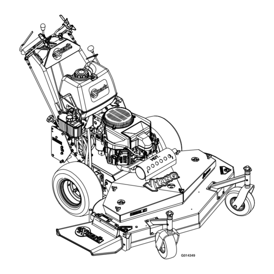
Page 15: Product Overview
Operation Product Overview Operation Note: Determine the left and right sides of the machine from the normal operating position. Controls Operator Presence Control (OPC) Levers Located on the upper handle assembly directly above the handle grips. When these levers are depressed, the OPC system senses that the operator is in the normal operator’s position. -
Page 16: Speed Control Lever
Operation as shown in Figure 4, and the drive levers are released, speed and moving it to the rear will decrease engine the drive wheels are engaged in the forward direction. speed. Moving the throttle forward into the detent is full position. Squeezing the left hand and/or right hand lever causes the left hand and/or right hand drive wheel Speed Control Lever... -
Page 17: Pre-Start
Operation Operating Instructions The knob can be adjusted so that machine will “track” straight ahead with the drive levers released. Open the Fuel Shut-Off Valve PTO Engagement Control Rotate the valve 1/4 turn counterclockwise to turn Located on left side of control console. fuel on. -
Page 18: Driving The Machine
Operation transporting, or when the unit is parked inside DANGER a building. An uncovered discharge opening will allow objects to be thrown in an operator’s or Driving the Machine bystander’s direction. Also, contact with the blade could occur. Thrown objects or blade Drive Lever/Neutral Lock Latch Operation contact can cause serious injury or death. -
Page 19: Transporting
Operation Driving in Reverse To move rearward in a straight line, squeeze drive levers into the reverse position. To turn left or right, squeeze the right hand drive lever to turn left and the left hand drive lever to turn right. To make a “zero turn”, squeeze either the left hand or the right hand drive lever back into the reverse position while the opposite drive lever is in a forward... -
Page 20: Maintenance
Maintenance Maintenance Note: Determine the left and right sides of the machine from the normal operating position. WARNING WARNING While maintenance or adjustments are being The engine can become very hot. Touching a hot made, someone could start the engine. engine can cause severe burns. -
Page 21: Periodic Maintenance
4. If the oil level is low, wipe off the area around the oil fill cap, remove cap and fill to the “FULL” Figure 6 mark on the dipstick. Exmark 4-Cycle Premium Engine Oil is recommended; refer to the Engine 1. Spring disc washer (cone towards bolt head) Owner’s manual for an acceptable alternative. -
Page 22: Check Safety Interlock System
Check Safety Interlock System Service Interval: Before each use or daily 1. For your safety, your Exmark mower is equipped with Operator Presence Controls, referred to as (OPC). When either the PTO is engaged, or the speed control lever is not in neutral and the operator removes both hands from the handles, the mower engine must stop. -
Page 23: Service Air Cleaner
2. Clean area around hydraulic reservoir cap and for additional information.) remove cap. Oil level should be to the top of the Every 200 hours/Yearly baffle inside the tank. If not, add oil. Use Exmark (whichever comes Premium Hydro Oil. Replace hydraulic reservoir first)—Replace the paper cap and tighten until snug. -
Page 24: Lubricate Grease Fittings
Maintenance 1. Stop engine, wait for all moving parts to stop, and remove key. Engage parking brake. 2. Remove the mower deck belt shield to check mower blade drive belt condition. 3. Look under engine deck to check the pump drive belt condition. - Page 25 Maintenance Note: Use only Exmark Part No. 109-4180 for CAUTION Summer use above 32°F (0°C) or P/N 1-523541 for Raising the mower for service or maintenance Winter use below 32°F (0°C) (Refer to Transmission relying solely on mechanical or hydraulic section in Specifications for filter specifications).
-
Page 26: Replace Emissions Air Intake Filter
Maintenance a steady flow of oil to flow out from under the housing. Retighten the capscrews. Do this for both pumps. Note: Hydraulic reservoir can be pressurized up to 5 psi to speed this process. 6. If either drive wheel still does not rotate, stop and repeat steps 4 and 5 above for the respective pump. -
Page 27: Thread Locking Adhesives
Maintenance Torque the slotted nut to 140-155 ft-lb (190-210 • Sheave retaining bolt in end of engine crankshaft. N-m). • Fuel tank bulkhead fitting threads Note: Do Not use anti-seize on wheel hub. Adhesives such as “Loctite RC/609 or RC/680” or •... -
Page 28: Adjustments
Maintenance Adjustments than adjusting axle position and number of spacers below caster support hub). Note: Disengage PTO, shut off engine, wait for Note that: all moving parts to stop, engage parking brake, and remove key before servicing, cleaning, or making any •... -
Page 29: Adjusting The Axle Position
Maintenance Cutting Height Adjustment Table (1 inch to 4 1/4 inches (2.5 cm-10.8 cm)) (cont'd.) Cutting Axle Number Of Spacers Number of 1/4 inch (.64 cm) Blade Spacers Below Spindle Height Position Below Caster Range (Figure 11) Support Hub 3/16 inch inch (1.2 cm) -
Page 30: Adjusting The Number Of Spacers Below Caster Support Hub
Maintenance 8. Remove jack. 9. Adjust wheel drive and brake linkages as required (see Brake and Wheel Drive Linkage Adjustment section). Figure 12 1. Four 1/2 inch (127 mm) 3. 3/16 inch (4.8 mm) spacers spacer 2. Quick Pin 4. Caster support 7. -
Page 31: Pto Engagement Linkage Adjustment
Maintenance Height Adjustment Table and notes in the Adjusting the Cutting Height section. 9. Install unused spacers between top of spindle and spindle nut. 10. Torque bolt to 75–80 ft-lb (102–109 N-m) (see Figure 13). Figure 14 1. The bellcrank just clears the gusset with the PTO engaged 2. -
Page 32: Blade Brake Adjustment
Maintenance mower to tighten, and toward front of mower to loosen belt tension (see Figure 15). For 48 inch Decks: If there is no adjustment left in the turnbuckle and the belt is still loose, the rear idler pulley can be repositioned in the front hole (see Figure 15). -
Page 33: Belt Guide Adjustment
Maintenance Figure 18 Shown with Blades Disengaged Figure 20 1. Blade Brake Rod 3. 1/8 inch to 3/16 inch 48 inch Belt Guide Location (.32–.47 cm) (Viewed from underneath the engine deck) 2. Spring Mounting Bolts 1. 1 3/8 inch (3.5 cm) 3. - Page 34 Maintenance Figure 21 Viewed from Left Side of Unit 1. Neutral Safety Switch 3. 5/16 inch (7.9 mm) 2. Actuating Tab in neutral position Figure 22 3. Pull the speed control lever back to neutral. Viewed from Left Side of Unit Check that the neutral safety switch actuating 1.
- Page 35 Maintenance disengaged whenever speed control levers are to neutral. Recheck the drive wheel rotation moved out of the neutral position. to see if further adjustment is necessary. Note: The neutral lock latches should be 4. The spring that keeps tension on the knob should normally not need adjustment.
-
Page 36: Tracking Adjustment
Maintenance Tracking Adjustment Park Brake Adjustment 1. Stop engine and wait for all moving parts to stop. 1. Stop engine and wait for all moving parts to stop. 2. Check the drive tire pressures and tire 2. Disengage the park brake. circumferences as stated in Check the Tire 3. -
Page 37: Cleaning
Maintenance Cleaning recycling center or according to your state and local regulations. Clean Engine Air Cooling System Service Interval: Before each use or daily 1. Stop engine and wait for all moving parts to stop. Engage parking brake. Remove key or spark plug wire(s). -
Page 38: Troubleshooting
Troubleshooting Troubleshooting Important: It is essential that all operator safety mechanisms be connected and in proper operating condition prior to mower use. When a problem occurs, do not overlook the simple causes. For example: starting problems could be caused by an empty fuel tank. The following table lists some of the common causes of trouble. - Page 39 Troubleshooting Problem Possible Cause Corrective Action Machine does not drive. 1. Bypass valve is not closed tight. 1. Tighten the bypass valve. 2. Drive or pump belt is worn, loose or 2. Change the belt. broken. 3. Drive or pump belt is off a pulley. 3.
-
Page 40: Schematics
Schematics Schematics Wiring Diagram TRANSMISSION SWITCH SWITCH N.O. N.O. FROM SAFETY SWITCH INTERLOCK MODULE N.O. GREEN YELLOW GREEN PARK BRAKE SWITCH BLACK SWITCH N.O. CONNECTORS ARE VIEWED FROM WIRE END ENGINE N.C. = NORMALLY CLOSED N.O. = NORMALLY OPEN G006968... - Page 41 Schematics...
- Page 42 No Claim of breach of warranty shall be cause for cancellation or rescission of the contract of sale of any Exmark mower. All warranty work must be performed by an authorized Exmark Service Dealer using Exmark approved replacement All implied warranties of merchantability (that the parts.
- Page 43 Notes:...
- Page 44 Notes:...
-
Page 45: Service Record
Service Record Date: Description of Work Done: Service Done By:... - Page 47 Figure 26 This page may be copied for personal use. 1. The maximum slope you can safely operate the machine on is 20 degrees. Use the slope indicator to determine the degree of slope of hills before operating. Do Not operate this machine on a slope greater than 20 degrees. Fold along the appropriate line to match the recommended slope.
- Page 48 SEE EXMARK’S COMPLETE LINE OF ACCESSORIES AND OPTIONS MID-MOUNT RIDING ACCESSORIES AND OPTIONS CUSTOM RIDE SEAT SUSPENSION SYSTEM OPERATOR CONTROLLED DISCHARGE FULL SUSPENSION SEAT ROLL OVER PROTECTION SYSTEM (ROPS) DECK LIFT ASSIST KIT SUN SHADE HITCH KIT TRASH CONTAINER LIGHT KIT...
Need help?
Do you have a question about the VIKING HYDRO and is the answer not in the manual?
Questions and answers