Table of Contents
Advertisement
CRDF/'S
MODEL NUMBER 917.258481
OWNER'S
MANUAL
®
oAssembly
- Operation
° Customer Responsibilities
° Service and Adjustments
° Repair Parts
CAUTION:
Read and follow
all safety rules and instructions
before operating
this equipment.
FOR CONSUMER
ASSISTANCE
HOT LINE, CALL THIS TOLL FREE NUMBER:
1-800-659-5917
/11111
.........
I
Advertisement
Table of Contents

Related Manuals for Craftsman 917.258481


Summary of Contents for Craftsman 917.258481
- Page 1 CRDF/'S ® MODEL NUMBER 917.258481 OWNER'S MANUAL oAssembly - Operation ° Customer Responsibilities ° Service and Adjustments ° Repair Parts CAUTION: Read and follow all safety rules and instructions before operating this equipment. FOR CONSUMER ASSISTANCE HOT LINE, CALL THIS TOLL FREE NUMBER: 1-800-659-5917 /11111 ..
- Page 2 SAFETY RULES Safe Operation Practices for Ride-On Mowers IMPORTANT: THIS CUTTING MACHINE iS CAPABLE OF AMPUTATING HANDS AND FEET AND THROWING OBJECTS., FAILURE TO OBSERVE THE FOLLOWING SAFETY INSTRUCTIONS COULD RESULT IN SER1OUS INJURY OR DEATH_ II1. CHILDREN GENERAL OPERATION •...
-
Page 3: Product Specifications
RIDING EQUIPMENT For two (2) years from the date of purchase, if this Craftsman Riding Equipment is maintained, lubricated and tuned up according to the instructionsin the owner's manua!, Sears will repair or replace, free of charge, any parts found to be defective in material or workmanship. - Page 4 TABLE OF CONTENTS SAFETY RULES ............MAINTENANCE SCHEDULE ........16 PRODUCT SPECIFICATIONS ........3 SERVICE AND ADJUSTMENTS ......20-25 STORAGE ..............CUSTOMER RESPONSIBILITIES ..... 3, 16-19 WARRANTY .._ ............TROUBLESHOOTING ..........27-28 TRACTOR ACCESSORIES .......... 5 REPAIR PARTS - TRACTOR ......... 30-47 ASSEMBLY ..............
-
Page 5: Accessories
RIES AND ATTACHMENTS ........,, ,,,i ii illl i ,,,,,,,,,,,,,,,,,,,,, Ill llllllll= These accessories and attachments were available throughmost Sears retail outlets and service centers when the tractor was purchased. Most Sears stores can order these items for you when you provide the modei number of your tractor.. ENGINE MAINTENANCE SPARK PLUG... - Page 6 CONTENTS OF HARDWARE PACK .... : ..,,,,, . ,,,,, i ,ll ........ Parts Bag contents shown full size Parts packed separately in carton Metal Seat (2) Sheet Screws #10-t6 x 1/2 Video Cassette (1) Locknut 3/8-24 (1) 2-3/8" Diameter Washer Steering Wheel Steering...
- Page 7 MBLY Your new tractor has been assembled at the factory with exception of those parts left unassembled for shipping purposes. To ensure safe and proper operation of your tractor alt parts and hardware you assemble must be tightened securely. Use the correct tools as necessary to insure proper tightness.
- Page 8 ASSEMBLY HOW TO SET UP YOUR TRACTOR INSTALL SEAT (See Fig. 3) Adjust seat before tightening adjustment boll CONNECT BATTERY (See Figs. 2A and 2B) Remove cardboard packing on seat pan. • Place seat on parr and assemble shoulder bolt. _ i,l_ll illllll iIIIllL...
- Page 9 ,/CHECKLIST BEFORE YOU OPERATE AND ENJOY YOUR NEW SHIELD TRACTOR, WE WISH TO ASSURE THAT YOU RECEIVE THE BEST PERFORMANCE AND SATISFACTION FROM THIS QUALITY PRODUCT° PLEASE REVIEW THE FOLLOWING CHECKLIST'; ¢" All assembly instructions have been completed_ ¢" No remaining loose parts in carton. Battery is properly prepared and charged..
- Page 10 O ERATION These symbols may appear on yourtractor or in literature supplied with the product., Learn and understand their meaning,, BATTERY CAUTION OR REVERSE FORWARD FAST SLOW WARNING ENGINE ON ENGINE OFF OIL PRESSURE CLUTCH LIGHTS ON LIGHTS OFF FUEL CHOKE MOWER HEIGHT DIFFERENTIAL...
- Page 11 OPERATION KNOW YOUR TRACTOR READ THIS OWNER'S MANUAL AND SAFETY RULES BEFORE OPERATING YOUR TRACTOR Compare the illustrations with yourtractorto familiarize yourselfwiththe locations ofvarious controlsand adjustments,, Save this manual for future reference, ATTACHMENT IGNITION CLUTCH LEVER LIGHT SWITCH SWITCH AMMETER LIFT LEVER PLUNGER THROTTLEJCHOKE...
- Page 12 The operation of any tractor can result in foreign objects thrown into the eyes, which can result in severe eye damage. Always wear safety glasses or eye shields while operating your tractor or performing any adjustments or repairs. We recommend a wide vision safety mask over the spectacles or standard safety glasses.
-
Page 13: Carburetor
OPERATION IA cA°T,o,: o0°0,0p°,°,°,h°oow°r without either the entire grass catcher, on mowers so equipped, or the dis- charge guard in place....ATTACHMENT CLUTCH LEVER "DISENGAGED" POSITION .POSITION ATTACHMENT LIFT LEVER HIGH POSITION FIG. 8 POSITION BEFORE STARTING THE ENGINE CHECK ENGINE OIL LEVEL (See Fig. - Page 14 TO START ENGINE (See Fig. 6) When starting the engine for the first time or if the engine CAUTION: Never' engage or disengage has run out of fuel, it will take.extra crankingtime to move freewheel lever while the engine is run- fuel from the tank to the engine..
- Page 15 OPERATION MOWING TIPS MULCHING MOWING TIPS • Tire chains cannot be used when the mower housing is IMPORTANT: BEST PERFORMANCE, KEEP attached to tractor. MOWER HOUSING FREE BUILT-UP GRASS ° Mower should be properly leveled for best mowing TRASH,, CLEAN AFTER EACH performance°...
- Page 16 RESPONSiBiLiTiES MAINTENANCE SCHEDULE " /_'___/_o_/" FILL IN DATES /_.._ _._O_ AS YOU COMPLETE ./'__ .._.'_O_ " ./_._/_SERVICE DATES REGULAR SERVICE ...... Check Brake Operation Check Tire Pressure Check for Loose Fasteners Sharpen/Replace Mower Blades t4#4 Lubrication Chart Check Battery LeveVRecharge Clean Battery and Terminals , I_ ..
- Page 17 CUSTOM B|LITI Ji i lll, ii ii i iiiJll,llllllllllll,,,, , ,,,,,,,,, ..ii ii ii/lllllll,i ° To check blade balance, you will need a 5/8" diameter TRACTOR steel belt, pin, or a cone balancer., (When using a cone Always observe safety rules when performing any mainte- balancer, follow the instructions supplied with bal- nance.
- Page 18 LITIES TRANSAXLE PUMP FLUID After oil has drained completely, replace oil drain plug and tighten securely. The transaxle was sealed at the factory and fluid mainte- Refill engine with oil through oil fill dipstick tube. Pour nance is not required for the life of the transaxle, Should the slowly.
- Page 19 CUSTOMER RESPONSiBiLiTiES ........... i lml,lt ,.t,lll ,lllllll. MUFFLER CLEAN AIR SCREEN (See Fig, 15) Air screen must be kept free of dirt and chaff to prevent inspectand replace corroded muffler and spark arrester (if engine damage from overheating_ Clean with a wire brush equipped) as it could create a fire hazard and/or damager or compressed air to remove dirt and stubborn dried gum SPARK PLUGS...
- Page 20 ADJUSTM ..CAUT,0": BEFO.E PE. O.M,NGSE.VlCE O"ADJUSTME"Tsi Depress clutch/brake pedal fully and set parking brake. • Place motion control lever in neutral (N) position. • Place attachment clutch in "DISENGAGED" position. ° Turn ignition key "OFF" and remove key. ° Make sure the blades and all moving parts have completely stopped.
- Page 21 AND ADJUSTMENTS FRONT-TO-BACK ADJUSTMENT (See Figs.. 20 and 21) TO LEVEL MOWER HOUSING IMPORTANT; DECK MUST BE LEVEL SIDE-TO-SIDE IF Adjust the mower while tractor is parked on level ground or THE FOLLOWING FRONT-TO-BACK ADJUSTMENT IS driveway.. Make sure tires are properly inflated (See NECESSARY, BE SURE TO ADJUST BOTH FRONT LINKS "PRODUCT SPECIFICATIONS"...
- Page 22 RVICE AND ADJUSTM w,uu TO REPLACE MOWER BLADE DRIVE BELT WITH PARKING BRAKE "ENGAGED" (See Fig. 22) NUT "A" The mower blade drive belt may be replaced withouttool& JAM NUT Park the tractor'on level surface_ Engage parkingbrake_ BELT REMOVAL - Remove mower from tractor (See 'q'O REMOVE MOWER"...
- Page 23 ........,,,,,,,,,,,,,,lllllllllllllllllllllllllllll ADJUSTMENTS SERVICE AND TO ADJUST STEERING WHEEL ALIGNMENT TO ADJUST MOTION CONTROL LEVER (See Fig. 25) If steering wheel crossbars are not horizontal (left to right) when wheels are positioned straight forward, remove steer- The motion control lever has been preset at thefactory and ingwheel and reassemble per instructionsin the Assembly adjustment should not be necessary.
- Page 24 SERVICE AND ADJUSTMENTS ................ : ......TO START ENGINE WITH A WEAK BATTERY TO REPLACE HEADLIGHT BULB (See Fig. 27) • Raise hood_ • Pull bulb holder out of the hole in the backside of the CAUTION: Lead,oacid batteries gener- grill,, ate explosive gases, Keep sparks, flame °...
-
Page 25: Throttle Control Cable 2
SERVICE AND ADJUSTMENTS ENGINE FINAL SETTING - Start engine and allow to warm for five minutes, Make ADJUST THROTTLE CONTROL CABLE final adjustments with engine running and shift/motion (See Fig. 29) control lever in neutral (N) position., ° Move throttle control lever to slow (,_h.) position,, With The throttle control has been preset at the factory and finger, rotate and hold throttle lever against idle speed adjustment should not be necessary., Check adjustmentas... -
Page 26: Storage
ENGINE Immediately prepare your tractor for storage at the end of the season or if the tractor wili not be used for 30 days or more° FUEL SYSTEM IMPORTANT: IT IS IMPORTANT TO PREVENT DEPOSITS FROM FORM}NG IN ESSENTIAL FUEL gasoline in the tank inside a building SYSTEM PARTS SUCH AS CARBURETOR, FUEL FILTER,... - Page 27 TROUBLESHOOTING POINTS CORRECTION CAUSE PROBLEM Fill fuel tank Out of fuel,, Wil! not start See "TO START ENGINE" in Operation section Engine not =CHOKED" properly. Wait several minutes before attempting to start Engine flooded, Replace spark plug. 4,, Bad spark plug,, Cleanfreplaee air filter Dirty air filter_, 6,, Replace fuel filter...
- Page 28 iiUlllllJlllllll i iiiii, TROU POINTS iiii iiiii iiiiiiiii IIIIIIIIII CAUSE CORRECTION PROBLEM iiii iiii iii Faulty operator+safety presence control system, 1+ Check wiring, switches and connections. If not Engine continues to run corrected, contact an authorized service center/ when operator leaves seat with attachment clutch department,, engaged...
- Page 29 TRACTOR - - MODEL NUMBER 917.258481 SCHEMATIC BLACK BATTERY { ..07..0 FUSE30 AMP. AMMETER STARTER 1___ (OPTIONAL) BLACK dll m,, _'-" iii _' t11@ WH|TE ..SOLENOID C_LUTCH t BRAKE (PEDAL UP) WHITE SEAT SWITCH IGNITION (NOT OCCUPIED) SWITCH W.ITE ,--.,_ t BLACK...
- Page 30 REPAIR PARTS TRACTOR -- MODEL NUMBER 917.258481 ELECTRICAL...
- Page 31 REPAIR PARTS TRACTOR -- MODEL NUMBER 9'17.258481 ELECTRICAL PART DESCRIPTION 144925 Batter'/12 Volt 25 Amp 74760412 Bolt, Hex Head 1/4-20 unc x 3/4 STD551025 Washer STD551125 Washer STD54t025 109238X Tube, Plastic, 12" 156417 Case, Battery Mech Hinge 109596X Clamp, Hose 147688 Fastner, Snap-ln 153664...
- Page 32 REPAIR PARTS TRACTOR -- MODEL NUMBER 917.258481 CHASSIS AND ENCLOSURES \_ 22...
- Page 33 REPAIR PARTS TRACTOR-- MODEL NUMBER 917.258481 CHASSIS AND ENCLOSURES PART DESCRIPTION 159530 Chassis Weldment 140356 Drawbar Stretch 17490612 Screw Thdrol 3/8-16 x 3/4 Ty-tt STD551025 Washer 13/32 x 3/4 x 16 Ga. 155272 Bumper Hood/Dash 155923 Saddle LT Flat Fender Shift 126842X Shield Ht Hood Kohf/Dia Engine 155138...
- Page 34 REPAIR PARTS TRACTOR - - MODEL NUMBER 917.258481 DRIVE...
- Page 35 REPAIR PARTS TRACTOR - - MODEL NUMBER 917.258481 DRIVE PART PART DESCRIPTION DESCRIPTION 140607 Transaxle (See Breakdown) Hydro G r 71170764 Bolt Hex 7/16 x4 Gr.. 5 Model 0310-0500 10040700 Washer 142431 Spring, Return, Brake 154778 Keeper, Belt Engine 144698 Screw Pulley, Transmission 142432...
- Page 36 REPAIR PARTS TRACTOR -- MODEL NUMBER 917,258481 STEERING ASSEMBLY _'--'-"'-_ ,_"_'-_...
- Page 37 REPAIR PARTS TRACTOR - - MODEL NUMBER 917.258481 STEERING ASSEMBLY PART DESCRIPTION 139768 Steering Wheel 154427 Axle Assembly STMP Dropped STL 156483 Spindle Assembly, L_H_ 157473 Spindle Assembly, R,H, 6266H Bearing, Race, Thrust, Hardened 12t748X Washer 25/32 x I-5/8 x 16 Gauge 19272016 Washer 27/32 x 1-1/4 x 16 Gauge 12000029...
- Page 38 NUMBER 917.258481 SEAT ASSEMBLY PART PART DESCRIPTION DESCRIPTION Bolt Rdhd Sht Nk 1/4-20xl-3/8 140122 Seat 3350 Blkiblk Craftsman 72050411 134300 140551 Bracket Pnt Pivot Seat (blk) Spacer Split 28 X 96 Zinc STD523710 Bolt Fin Hex 3/8-16unc X 1 121250X...
- Page 39 Decal, Cap Cnsmr Heip Line Srs 150333 150677 Decal, Hood Slope Lh Craftsman 156787 Decal, Mower EZ3 Mulching Decal, Grille Craftsman S_p LT Dov 150680 149917 Decal, Fender, Auto, Trans Srs Wt Decal, Maint Customer Sears Dorn 133644 Decal, Lightbox...
- Page 40 REPAIR PARTS TRACTOR - - MODEL NUMBER 917,258481 ENGINE OPTIONAL EQUIPMENT Spark Arrester...
- Page 41 REPAIR PARTS TRACTOR - - MODEL NUMBER 917.258481 ENGINE PART DESCRIPTION 132759 Controf Throt Rh Blk Pdl 15 t0 '17720410 Screw Hex Thd Cut 1/4-20x5/8 T Engine (See Breakdown) B&S ..Model No, 28N707-0173-01 Muffler Exhaust B&S Lt 137352 Gasket 1 313 ld Tin Plated 272293 13280324 Nipple Pipe 3/8 Npt X 3"...
- Page 42 REPAIR PARTS TRACTOR -- MODEL NUMBER 917.258481 LIFT 161718 13---_...
- Page 43 PARTS REPAIR TRACTOR - - _IODEL NUMBER 917.258481 LIFT PART DESCRIPTION 159460 Wire Asm Inner/Sprg. wlPLngr Lt Shaft Asm. Lift 159474 Pin Groove 105767X 12000002 E Ring #5133-62 Washer 21/32 x 1 x 21 Ga,, 19211621 120183X Bearing Nytong 125631X Grip Handle Fluted 122365X Button Plunger Read...
- Page 44 REPAIR PARTS TRACTOR -- MODEL NUMBER 917.258481 MOWER 21 22...
- Page 45 REPAIR PARTS TRACTOR- - MODEL NUMBER 917.258481 MOWER PART PART DESCRIPTION DESCRIPTION 144393 Mower Housing 155066 Roller Assembly, Cam Follower Bolt Bolt, Shoulder #10-24 Grade 5 STD533107 131340 Locknut Bracket Assembly,Sway Bar, Front STD541410 138017 Bolt, Shoulder 5f16-18 UNC 138440 139888 Bracket Assembly, Sway Bar 131845X900...
- Page 46 REPAIR PARTS TRACTOR - - MODEL NUMBER 917.258481 HYDRO GEAR TRANSAXLE - MODEL NUMBER 310-0500 63 64...
- Page 47 REPAIR PARTS TRACTOR - - MODEL NUMBER 917.258481 HYDRO GEAR TRANSAXLE - MODEL NUMBER 310-0500 KEY PART KEY PART DESCRIPTION NO. NO. DESCRIPTION NO. NO. Locknut, Hex 5/16-24 UNJC 142986 Housing, Lower 150778 Brake Rotor/Stator Kit 142987 Assembly, Upper Housing 142958 Washer 7/16 x 7/8 x .060 142932...
- Page 48 REPAIR PARTS TRACTOR- - MODEL NUMBER 917,258481 BRIGGS & STRATTON ENGINE - MODEL NUMBER 28N707, TYPE NUMBER 0173-01 634A "_ REQUIRES SPECIAL TOOLS TO INSTALL. SEE REPAIR INSTRUCTION MANUAL. 1022 1034 !294_ 1029 1023 1026...
- Page 49 REPAIR PARTS TRACTOR - - MODEL NUMBER 917.258481 BRIGGS & STRATTON ENGINE - MODEL NUMBER 28N707, TYPE NUMBER 0173-01 1033 VALVE OVERHAUL ....i'21 cARBuREToR OVERHAUL _i___! ..i _ ÷ 87 _ ___618 _ 634 634B REQUIRES SPECIAL TOOLS TO INSTALL.
- Page 50 REPAIR PARTS TRACTOR-- MODEL NUMBER 917.258481 BRIGGS & STRATTON ENGINE - MODEL NUMBER 28N707, TYPE NUMBER 0173-01 634A 868 868A _ 842 284A 358 GASKET 977 cARBURETOR GASKET SET 1044 305_ 1006...
- Page 51 REPAIR PARTS TRACTOR -- MODEL NUMBER 917.258481 BRIGGS & STRATTON ENGINE - MODEL NUMBER 28N707, TYPE NUMBER 0173-01 1019 LABEL KIT] i1058 OWNER'S MANUALI 1090...
- Page 52 REPAIR PARTS TRACTOR -- MODEL NUMBER 917.258481 BRIGGS & STRATTON ENGINE - MODEL NUMBER 28N707, TYPE NUMBER 0173-01 KEY PART KEY PART NO. NO. DESCRIPTION NO. NO. DESCRIPTION 94098 ** Screw, Throttle Cylinder Assembly 496412 495800 Screw, Idle Speed 399265 Bearing, Cylinder 231789 * Seal, Oil...
- Page 53 REPAIR PARTS TRACTOR- - MODEL NUMBER 9'17.258481 BRIGGS & STRATTON ENGINE - MODEL NUMBER 28N707, TYPE NUMBER 0173-01 KEY PART KEY PART NO, NO. DESCRIPTION NO. NO. DESCRIPTION 284A 94073 Screw, Hex Head 729A 225170 Retainer, Wire 810068 Screw, Set 741 262932 Gear, Timing 304 496280...
- Page 55 SUGGESTED GUIDE FOR SIGHTING SLOPES FOR SAFE OPERATION ONLY RIDE UP AND DOWN HILL, NOT ACROSS HILL SIGHTING "" ..SIGHT AND HOLD THIS LEVEL WITH SKY LINE OR TREE. 15° MAX. Operate your Tractor up and down the face of slopes (not &...
-
Page 56: Replacement
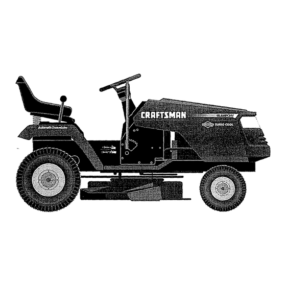
CRI:IFTIMI:IN OWNER'S 15.5 HP IC MANUAL ELECTRIC START 42" MOWER HYDROSTATIC (AUTOMATIC) LAWN TRACTOR MODEL NO. Each tractor has its own modet number., Each engine has its own model number_ 917.258481 The model number for your tractor will be found on the modet plate located under the seat, The model number for your engine will be found on the btower housing of the engine.
Need help?
Do you have a question about the 917.258481 and is the answer not in the manual?
Questions and answers