Advertisement
Available languages
Available languages
Quick Links
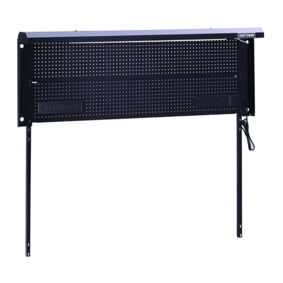
OPERATOR'S
MANUAL
PART#
F1726
BACKWALL
WITH METAL
PEGBOARD
CAUTION:
Backwall
MUST be attached
to the Workbench
before the
top is attached.
CAUTION:
Read and follow all Safety Rules and Operating
Instructions
before first use of this product.
Distributed
by Sears Brands
Management
Corporation.,
Hoffman
Estates,
IL 60179
F1726
Advertisement

Subscribe to Our Youtube Channel
Related Manuals for Craftsman F1726


Summary of Contents for Craftsman F1726
- Page 1 OPERATOR'S MANUAL F1726 PART# BACKWALL WITH METAL PEGBOARD CAUTION: Backwall MUST be attached to the Workbench before the top is attached. CAUTION: Read and follow all Safety Rules and Operating Instructions before first use of this product. Distributed by Sears Brands Management Corporation., Hoffman...
-
Page 2: Tools Required
Use appropriate safety equipment when using power and hand tools. Failure to do so may cause personal injury or product damage. Use adequate manpower when assembling and moving this unit. Failure to do so may cause personal injury or product damage. DO NOT stand on this product. - Page 3 o© ©...
-
Page 4: Top Removal
WARNING: Backwall with Metal Pegboard is only to be attached to one of the following Workbenches: 14929, 14928, 14925 and 14940. TOP REMOVAL: • Remove and reuse fasteners from wood top. • Remove top from workbench base. STEP 1 : •... - Page 5 STEP 4: STEP 5: DD(6) HH(1) (8'ONLY) KK(2) EE(6) RR(2) CC(4) LL(2) • Assemble (2) LL and (2) JJ loosely together. • Attach light assembly B to Backwall using (4) AA, (4) • Place hardware assembly into top slots in light housing F. BB, (4) CC, (6) DD, and (6) EE as shown.
- Page 6 STEP 7: STEP 6: GG(2) EE(2) NN(2) FF(6) NOTE: To reattach the top, new pilot holes may need to be Note: Outlet strip may be mounted on left or right side. marked and drilled. Right side mounting shown. • Place top on the bench in the desired location. •...
- Page 7 STEP 9: HH(4) • Install grommets (4) HH in holes in E.
-
Page 9: Montaje
MANUAL DE USUARIO MONTAJE EN PARED CON TABLERO METALICO PRECAUCION: La parte posterior DEBE fijarse al banco de trabajo antes de unir la parte superior. ATENCION Lea y siga todas las Normas de Seguridad y las Instrucciones de Funcionamiento antes de utilizar por primera vez este producto. - Page 10 ADVERTENCIAS Y PRECAUCIONES DE SEGURIDAD: • Utilice el equipo de seguridad adecuado cuando emplee herramientas electricas. De Io contrario, podria causarle lesiones personales u ocasionar daSos al producto. • Utilice el personal adecuado para el montaje y el traslado de esta unidad. De Io contrario podria ocasionarse lesiones personales o daSar el producto.
- Page 12 ADVERTENCIA: El Panel Posterior con Tablero de Metal Backwall 14943/14944 s61o debe ser colocado en los siguientes Bancos Trabajo: 14929, 14928, 14925 and 14940. REMOCION DE LA PARTE SUPERIOR: • Retire y vuelva a utitizar los sujetadores det tope de madera. •...
- Page 13 PASO PASO 5: HH(1) (8 KK(2) SOLAMENTE) DD(6) EE(6) RR(2) LL(2) CC(4) JJ(2) • Monte (2) LL y (2) JJ libremente junto. • Ate et montaje ligero B a Backwall usando (4) el AA, (4) BB, (4) CC, (6) DD y (6) EE como se muestra. •...
- Page 14 PASO 7: PASO 6: GG(2) EE(2) NN(2) FF(6) NOTA: Para reatar ta tapa, los nuevos agujeros Nota: La regteta de tomacorrientes puede montarse at experimentales pueden necesitar ser marcado y ser lado izquierdo o derecho. Se itustra con montaje del lado derecho.
- Page 15 PASO 9: HH(4) • Instale los ojales (4) HH en agujeros en E.
Need help?
Do you have a question about the F1726 and is the answer not in the manual?
Questions and answers