Table of Contents
Advertisement
Quick Links
Advertisement
Table of Contents

Related Manuals for Ericsson M-PD


Summary of Contents for Ericsson M-PD
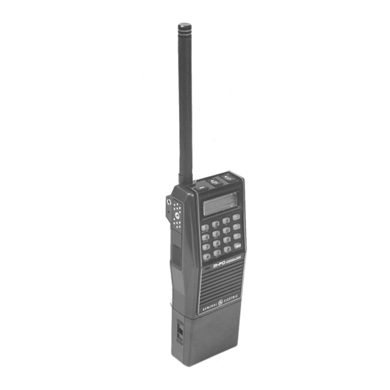
- Page 1 136-174 MHz PERSONAL TWO-WAY FM RADIO COMBINATION INCLUDES SERVICE SECTION ....LBI-31677 Ericsson Inc. Private Radio Systems Mountain View Road Lynchburg, Virginia 24502 1-800-528-7711 (Outside USA, 804-528-7711)
-
Page 2: Table Of Contents
LBI-31629 SPECIFICATIONS TABLE OF CONTENTS SYSTEM Page Frequency Range FCC Identification Number 136 MHz to 160 MHz AXA9WNTR-145-A SPECIFICATIONS ........... . 150 MHz to 174 MHz AXA9WNTR-145-B Frequency Stability... -
Page 3: System
Guard by programming two different radio channels HIGH CAPACITY with the same frequency information but only one with BATTERY Ericsson GE’s M-PD System Personal Radio is a high- (Standard) Channel Guard capability. quality, high-performance, two-way, FM, communications unit consisting of a transmit/receive circuit with a frequency syn- Programmable Multi-Code Digital Channel Guard thesizer controlled by a microprocessor. -
Page 4: Operation
(transmit/re- packs are available in three capacities: standard, high and ex- UDC through four connections. The Ericsson GE first IF signal. ceive/synthesizer) is assembled. tra high. To charge these battery packs, charges are available... - Page 5 LBI-31629 Assemble these parts into one unit according to the fol- Display lowing procedure and as shown in Figure 1 - M-PD Operat- ing Controls and Accessories. If BSY If BSY lights, it means that the channel is busy. NOTE Either the antenna or the RF connector should Adjust the audio volume to the desired level by be connected to the M-PD radio main unit, as...
-
Page 6: System Analysis
Press the secondary key and the SEND key as in Step 3 of To Make a Telephone Call. SYSTEM ANALYSIS Ericsson GE M-PD Personal radios are two-way, FM ra- dios designed for public communications. The M-PD Sys- Figure 3 - Amplifier Module (TX-Amp) - Page 7 LBI-31629 Q202. The RF power output from Pin 2 of the TX-Amp RF Amplifier/Mixer: module A201 is connected through a resistor attenuator to Pin 1 of the PA module where it is applied to the input of the The RF Amplifier/Mixer circuit contains two third order RF power amplifier stages.
- Page 8 LBI-31629 Synthesizer Circuit (phase) and the reference (VCTCXO) and is applied to the VCO on frequency. A lock detect output is developed from Pin 9 output of A102. This output is checked by the micro- The Synthesizer circuit contains Phase-Lock-loop mod- computer to prevent transmission before the VCO is on fre- ule (PLL) A102, VCTCXO Reference Oscillator module quency.
- Page 9 LBI-31629 TX Power, TX Modulation Data flexible cable and rubber contacts. The cable connects with the CONTROLLER CIRCUIT Signaling Board microcomputer. Squelch Data The Signaling Board consists of the following circuits: This controller circuit consists of control circuits and Display Data ...etc. UDC Connector audio circuits.
-
Page 10: Maintenance
LBI-31629 Charger combinations for charging the battery packs are Disassembly Procedure (See Figure 11): PREVENTIVE MAINTENANCE Step 6: available with charge times of 1 hour, 3 hours and 16 hours. A combination can be a single unit desk or a vehicular charger. It Unplug the LCD control flex circuit at from the con- To ensure a high operating efficiency and to prevent me-... - Page 11 LBI-31629 Figure 11 - Disassembly Figure 13 - Disassembly Step 2 Figure 14 - Disassembly Step 3 Figure 12 - Disassembly Step 1...
- Page 12 LBI-31629 Figure 15 - Disassembly Step 4 Figure 17 - Disassembly Step 6 Figure 16 - Disassembly Step 5 Figure 18 - Disassembly Step 7...
-
Page 13: Intrinsically Safe Usage
LBI-31629 PDNC1D (19B234804P3) Antenna, 162-174 MHz, INTRINSICALLY SAFE USAGE Helical Selected personal radios with appropriate factory installed PDNC1E (19B234804P11) Antenna, 403-440 MHz, F4 Options are certified as Intrinsically Safe by the Factory Helical Mutual Research Corporation for use in Class 1, Division 1 or PDNC1F (19B234804P12) Antenna, 440-470 MHz, 2, hazardous locations in the presence of Groups C and D at- Helical... -
Page 14: Reduced Capacity In Nickel- Cadmium Batteries
1.0 Volt is not necessary for reconditioning a cell. ing returned under warranty or scrapped. If the "Memory Effect" is a fact, a procedure for reconditioning it should be A full charge cycle using an appropriate Ericsson GE performed as follows: charger. -
Page 15: Interconnection Diagrams
LBI-31629 INTERCONNECTION DIAGRAM... -
Page 16: Radio Board
OUTLINE DIAGRAM LBI-31629 COMPONENT SIDE SOLDER SIDE RADIO BOARD A4WE03739/40... - Page 17 LBI-31629 SCHEMATIC DIAGRAM RADIO SCHEMATIC DIAGRAM WITH TYPICAL VOLTAGE A4WE03739/40...
-
Page 18: Controller Board
OUTLINE DIAGRAM LBI-31629 COMPONENT SIDE SOLDER SIDE Controller Board A4WE04023... -
Page 19: Controller Board
LBI-31629 SCHEMATIC DIAGRAM Controller Board A4WE04023... -
Page 20: Signaling Board
OUTLINE DIAGRAM SCHEMATIC DIAGRAM LBI-31629 COMPONENT SIDE SOLDER SIDE Signalling Board M-PD Signaling Board A4WE04024 A4WE04024... -
Page 21: Lcd Board
LBI-31629 OUTLINE DIAGRAM SOLDER SIDE COMPONENT SIDE LCD Board A4WE03737... - Page 22 SCHEMATIC DIAGRAM LBI-31629 LCD 1 Board A4WE03737...
-
Page 23: Battery Packs
LBI-31629 SCHEMATIC & OUTLINE DIAGRAM Battery Packs... -
Page 24: Mechanical Parts Breakdown
MECHANICAL PARTS BREAKDOWN LBI-31629 M-PD EXPLODED VIEW SYSTEM TYPE A1WL09006... - Page 25 LBI-31629 PARTS LIST...
- Page 26 PARTS LIST LBI-31629...
- Page 27 LBI-31629 PARTS LIST...
-
Page 28: Signaling Board
PARTS LIST LBI-31629...
Need help?
Do you have a question about the M-PD and is the answer not in the manual?
Questions and answers