Table of Contents
Advertisement
Quick Links
Mobile Communications
M-RK
VHF
PERSONAL TWO-WAY FM
RADIO COMBINATION
TABLE OF CONTENTS
Service Assemblies . . . . . . . . . . . . . . . . . . . . . . . . LBI-38746
Service Section . . . . . . . . . . . . . . . . . . . . . . . . . . . LBI-38738
Disassembly and Assembly . . . . . . . . . . . . . . . . . . . . LBI-38741
Maintenance Manual
LBI-38734
Advertisement
Table of Contents

Related Manuals for Ericsson M-RK


Summary of Contents for Ericsson M-RK
- Page 1 LBI-38734 Mobile Communications M-RK PERSONAL TWO-WAY FM RADIO COMBINATION TABLE OF CONTENTS Service Assemblies ......LBI-38746 Service Section ......LBI-38738 Disassembly and Assembly .
-
Page 2: Table Of Contents
LCD/KB Flex Assy. (M-RK II) ........ -
Page 3: Specifications
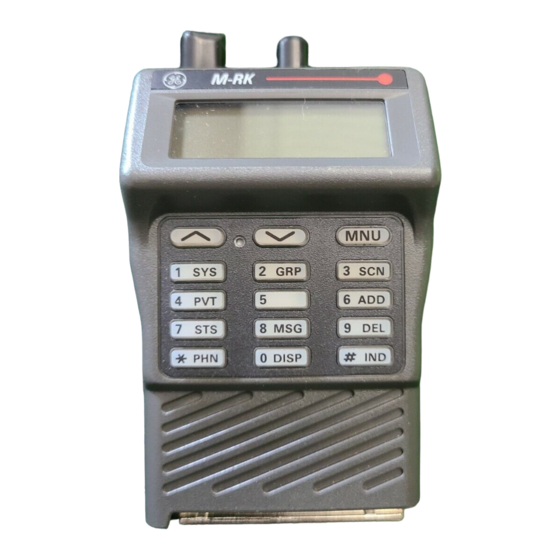
Figure 1-2 - M-RK II Controls and Accessories ....... . -
Page 4: Specifications
LBI-38734 SPECIFICATIONS (Continued) Dimensions (HxWxD)(M-RKII) (with 1200 mAH battery) 176.8x68x40.6 mm (7x2.7x1.6 inches) Weight (M-RKII) 20.3 ounces (with 1200 mAH battery) Operable Temperature Range -30º to +60ºC (-22º to +140ºF) TRANSMIT RF Power Output 0.5 to 6 watts Spurious Emissions -75dBc ±5 KHz Maximum Deviation... -
Page 5: Description
A group consists of several users with a common group identification (ID). A radio may have several groups, but the (M-RK II) may be programmed on or off per group. selected group determines who the unit can call at any spe- The side-tone beep, related to the operation of the cific time. -
Page 6: Radio Assembly
The transmitter is modulated at both rotary switch, AF volume with switch. the VCO and the VCTCXO. d. A battery pack that fits the M-RK main unit. b. VCTCXO Module -- The VCTCXO is a voltage controlled, temperature compensated crystal oscilla- e. - Page 7 LBI-38734 Figure 1-1 - M-RK I Controls and Accessories...
-
Page 8: Figure 1-2 - M-Rk Ii Controls And Accessories
LBI-38734 Figure 1-2 - M-RK II Controls and Accessories... -
Page 9: System Analysis
Receive Circuit SYSTEM ANALYSIS The M-RK receive circuit, as shown in Figure 2, con- Refer to Figures 2 and 3. The M-RK radio consists of sists of the following circuits: three major printed wire boards as follows: • RF Amplifier/Mixer •... - Page 10 LBI-38734...
- Page 11 LBI-38734...
- Page 12 LBI-38734...
-
Page 13: Figure 4 - Power Amplifier (Pa) Vhf
LBI-38734 Figure 4 - Power Amplifier (PA) VHF Figure 5 - LPF. DC. T/R SW. Module (U8) VHF/UHF Figure 6 - RF Amplifier/Mixer... -
Page 14: Second If Amplifier/Discriminator (U11)
LBI-38734 Figure 7 - First IF Amplifier Second IF Amplifier/Discriminator (UII) Phase-Lock-Loop Module (U2) The Second IF Amplifier/Discriminator circuit (Figure The PLL module U2 contains a reference frequency, di- 8) contains FM IF IC UII (TA31132F) and 455 KHz ce- vider, phase detector, and a programmable divider. -
Page 15: Logic Circuit
Physically, this circuit consists of two circuit board as • Custom CMOS DSP Chip (U3) follows: • Control Board Assy. • Custom CMOS ASP Chip (U7) • LED Flex Assy. (M-RK I) • CMOS Inverters (U12) • LCD/KB Flex Assy. (M-RK II) • CMOS OR gates (UIS) -
Page 16: Microcomputer
Voltage Regulator (U9, UIO) • Controlling the LED display (M-RK I) Voltage regulator U9, UIO, QI generate 5 VDC for Con- • Loading data to the LCD display processor (M-RK II) trol Board and LCD/KB Flex Board. • Controlling the audio circuit (processor) Audio Amplifier (UII) •... -
Page 17: Led Flex Assy. (M-Rk I)
There are 15 button of key switches (keypads) on the Transmit Circuit Alignment System model of M-RK II. The keypads consist of flexible cable and rubber contacts, and each connect through cable to the microcompurter. The transmit circuit is factory turned and should not re- quire any readjustment. -
Page 18: Synthesizer Circuit
The M-RK radio is designed to meet MIL-810-D speci- tion. They should be repeated after the first month of opera- fication for Blowing Rain. All access to the M-RK radio are tion, then again one time each year. protected from water entry by suitable gaskets and seals.
Need help?
Do you have a question about the M-RK and is the answer not in the manual?
Questions and answers