Table of Contents
Advertisement
Quick Links
LBI-38736
Mobile Communications
M-RK
806 - 869 MHz
PERSONAL TWO-WAY FM
RADIO COMBINATION
TABLE OF CONTENTS
Service Assemblies . . . . . . . . . . . . . . . . . . . . . . . . LBI-38746
Service Section . . . . . . . . . . . . . . . . . . . . . . . . . . LBI-38749
Disassembly and Assembly . . . . . . . . . . . . . . . . . . . . LBI-38741
Maintenance Manual
Advertisement
Table of Contents

Subscribe to Our Youtube Channel
Related Manuals for Ericsson M-RK


Summary of Contents for Ericsson M-RK
- Page 1 LBI-38736 Mobile Communications M-RK 806 - 869 MHz PERSONAL TWO-WAY FM RADIO COMBINATION TABLE OF CONTENTS Service Assemblies ......LBI-38746 Service Section .
-
Page 2: Table Of Contents
Synthesizer Circuit ......... . . Copyright © December 1992, Ericsson GE Mobile Communications Inc. - Page 3 Figure 1 - M-RK I Controls and Accessories ....... . .
-
Page 4: Specifications
LBI-38736 SPECIFICATIONS (Continued) Dimensions (HxWxD)(M-RKII) 176.8x68x40.6 mm (7x2.7x1.6 inches) (with mAH battery) Weight (M-RKII) 20.3 ounces (with mAH batery) Operable Temperature Range -30º to +60ºC (-22º to +140ºF) TRANSMIT RF Power Output 0.5 to 3 watts Spurious Emissions -55dBc ±4 KHz Maximum Deviation FM Hum &... -
Page 5: Description
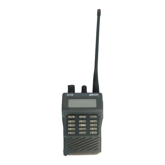
• 16 Character Dot Matrix Alphanumeric Crystal The M-RK Personal Radio is designed to operate in a Display -- This display is used to exhibit the M-RK Digital Trunking System or as a conventional radio condition of the radio. - Page 6 LBI-38736 Figure 1 - M-RK I Controls and Accessories...
-
Page 7: Figure 2 - M-Rk Ii Controls And Accessories
LBI-38736 Figure 2 - M-RK II Controls and Accessories... -
Page 8: Radio Assembly
LBI-38736 Physically an M-RK radio consists of three main printed Second IF (455 KHz) -- Consists of one IC and wire board assemblies and a battery pack as follows : three BPF containing the second mixer, the second IF amplifier, and the FM detector. The second IF... -
Page 9: System Analysis
LBI-38736 Circuit illustrations shown are simplified representatives SYSTEM ANALYSIS of actual circuits. Refer to Figures 3 and 4. The M-RK radio consists of They are intended only to illustrate basic circuit func- three printed wire boards as follows : tions. -
Page 10: Figure 4 - Logic Block Diagram
LBI-38736 Figure 4 - Logic Block Diagram... -
Page 11: Power Amplifier Module (U7)
Power Amplifier Module (U7) Receive Circuit Power Amplifier (PA) U7 is a five-stage, wideband am- The M-RK receive circuit, as shown in Figure 3, con- plifier module with an input and an output impedance of 50 sists of the following circuits : ohms (Figure 5). -
Page 12: First If Amplifier
LBI-38736 First IF Amplifier ter to the IF amplifier and FM detector circuits. The recov- ered audio from the FM IF IC is connected to J1-3B. The first IF amplifier contains a amplifier circuit and two crystal filters of two poles, respectively (refer to Figure Synthesizer Circuit 8). -
Page 13: Voltage-Controlled Oscillator (U5)
LBI-38736 • 5 volt Regulator (U9,10) Serial data from the microcomputer is shifted into the PLL to set the division parameter which establishes the fre- quency. A clock signal is provided on another input and the Microcomputer data is latched with the enable input. The main microcomputer circuit in this radio consists of Voltage-Controlled Oscillator (U5) microprocessor, HD6475328FI10 (U2), 2 Kx8E2PROM... -
Page 14: Digital Signal Processor (Dsp)(U3)
There are 15 button of key switches (keypads) on the The Audio processor consists of a one-chip IC accom- System model of M-RK II. The keypads consist of flexible modating almost all the audio functions. The audio func- cable and rubber contacts, and each connect through cable tions are under control of the microcomputer in compliance to the microcompurter. -
Page 15: Maintenance
INITIAL ADJUSTMENT when necessary. Refer to the applicable alignment proce- dure and troubleshooting sheet (found in the Service Sec- The M-RK radio personality is programmed using an tion) for typical voltage readings. IBM compatible personal computer and programming soft- ware. The procedure is described in the applicable program- Frequency Check ming manual. -
Page 16: Replacement
Service Sec- The M-RK radio is designed to meet MIL-810-D speci- tion. fication for Blowing Rain. All access to the M-RK radio are protected from water entry by suitable gaskets and seals. However, degradation due to use or disassembly during re- pairs, may affect the integrity of the seals as provided by factory assembly.
Need help?
Do you have a question about the M-RK and is the answer not in the manual?
Questions and answers