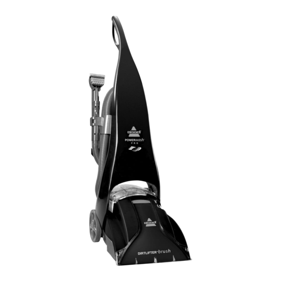
Table of Contents
Advertisement
BISSELL
Service Guide
Model 1697/1698 Power Steamer Pro Series
Contents:
Section
Troubleshooting .........................................................
1
Exploded View Drawing ...............................................
2
Parts List ..................................................................
3
Wiring Diagram .........................................................
4
Identification
of Date Code and Model Number ....................
5
Functional
Test ..........................................................
6
•
Pump ..................................................................
7
•
Motor .................................................................
8
•
Switch ................................................................
9
•
Heater ................................................................
10
•
Power Cord ..........................................................
11
•
Wiring Harness ......................................................
12
•
Detent Lever .........................................................
13
•
Wheels ...............................................................
14
•
Hose ..................................................................
15
•
Brush Roll ............................................................
16
17
Photograph
- Tubing Routing in the Base ..........................
Advertisement
Table of Contents

Summary of Contents for Bissell 1697
-
Page 1: Table Of Contents
BISSELL Service Guide Model 1697/1698 Power Steamer Pro Series Contents: Section Troubleshooting ............Exploded View Drawing ..........Parts List ..............Wiring Diagram ............Identification of Date Code and Model Number ....Functional Test ............Repair Guide • Pump ..............•... -
Page 2: Troubleshooting
1. Troubleshooting Guide No Spray 1) with unit off, fill both tanks with water, remove and replace each tank, turn on and pull trigger 2) check pump belt for damage or wear 3) check flow indicator filter, tighten cap securely 4) hold tank over sink, manually activate valve on the bottom of each tank and check for flow, check for gaskets on the exit port of each tank 5) check for debris in the receivers for each tank... - Page 3 Heater light doesn't come on 1) check actuation of the switch 2) unplug unit, remove lower front handle cover and check for loose wires 3) replace light assembly hot water 1) check that heater switch is on, let the heater warm-up for about 2 minutes and check the temperature of the water coming out the spray tips compared to the temperature in the tank (note: upholstery tool does not spray heated water) 2) unplug unit, remove lower handle cover and check for loose wires...
-
Page 4: Parts List
3. Parts List PARTNO. P.fiBzl_ 0109201 UPH TOOL 4" 0139754 WHEEL 6030961 WINOOW FOR 4" TOOL O13O44O BASE BRUSH FOR 4" TOOL 6O3O966 0100105 AUTOMIX ASSY 0159155 TUFF STAIN TOOL 3" WIDE 0139131 BARE FLOOR A'rrACHMERT 0149155 BRUSH FOR 3" TOOL 0130050 PIVOT ARM-RIGHT WINDOW FOR 3"... -
Page 6: Wiring Diagram
4. Wiring Diagram 9LACK 0105601 LIGHTED LIGHT ASST. SWITCH 2 NOEN 120 V TIO862t t NEAT NON-LIGHTEDI SWITCNI POWER SWITCH OLACK 01049_ JUMPER BLACK POWER CORD WHITE 0102811 1813 SVT ITOH 1698A) WHITE 1813 SVT (FOR 1608) 0104451 GREEN GREEN HARNESS IIEATFH GREEN... -
Page 7: Repair Guide
Identification of Date Code/Model Number • Underside of the foot of the unit is a motor rating label that contains the model number and the date of manufacture. Initial Functional Test • Plug unit into a HI-POT tester to detect dielectric failures. •... -
Page 8: Motor
8. Motor • Remove six screws from the main housing • Remove window, flow indicator cap and belt access door • Unsnap main housing from front of base • Remove main housing assembly • Remove smooth belt • Remove four screws surrounding the motor cover •... -
Page 9: Power Cord
Remove leads and tubing from heater Remove heater assembly Install new heater assembly and reassemble (Note: One or more of the insulator caps on the heater may come off when opening the cover. These must be put back in place prior to closing the handle.) Power Cord Remove two screws from the front of upper handle •... -
Page 10: Wheels
every repaired unit. Also, tubing and ducts should be routed per Photograph #1, section 17) Wheels • Remove six screws from the main housing • Remove window, flow indicator cap and belt access door • Unsnap main housing from front of base •...


Need help?
Do you have a question about the 1697 and is the answer not in the manual?
Questions and answers