Epson FX-870 Service Manual
Hide thumbs
Also See for FX-870:
- User manual (184 pages) ,
- Service manual (138 pages) ,
- Product support bulletin (20 pages)
Table of Contents
Advertisement
Quick Links
Advertisement
Chapters
Table of Contents

Related Manuals for Epson FX-870


Summary of Contents for Epson FX-870
-
Page 1: Service Manual
FX-870/1170 SERVICE MANUAL Revision Level ® EPSON Printed on Recycled Paper. -
Page 2: Fcc Compliance Statement
If this equipment has more than one interface connector, do not leave the cables connected to unused interfaces. Changes or modifications not expressly approved by the manufacturer could void the user’s authority to operate the equipment. Epson f%87W1170... -
Page 3: Copyright Notice
America, Inc., assumes no responsibility for errors and omissions. Neither Epson America, Inc., nor its affiliates shall be liable to the purchaser of this product or third parties for damages, losses, costs, or expenses incurred by purchaser or third parties as a result of: accident, misuse, or abuse of this product or unauthorized modifications, repairs, or alterations to this product. - Page 4 CAUTION 1. Repairs on Epson products should be performed only by an Epson certi- fied repair technician. 2. Make certain that the source voltage is the same as the rated voltage listed on the serial number/rating plate.
-
Page 5: How To Use This Manual
You can use the set of troubleshooting tables and flowcharts to isolate the problem as far as possible. If you encounter problems using software, the !Z’roubZeshooting section lists supported Epson ESC/P control codes and symbol sets. There are tips for graphics handling and an explanation of how to read hex dump printouts. Epson FX-87W1170... -
Page 6: Principles Of Operation
4 Disassembly/Assembly This chapter lists the tools you need and gives the recommended procedure for removing and replacing components. 5 Adjustments, Maintenance, and Lubrication This chapter provides instructions for performing the platen gap adjustment and the bidirectional adjustment procedure. There is also a description of the lubricants required and an illustration of the points at which the printer needs to be lubricated after repair of the mechanism. - Page 7 (506) 34-6666 Phone: (541) 394-2439 Fax: (506) 25-5709 Fax: (541) 322-4637 Epson Mexico S.A. De C.V. Epson Venezuela S.A. Av. Ejercito NacionaI No. 904 Edif. Epson - La Urbina 6 Piso Col. PaIamas Polanco Caracas, Venezuela Condigo Postal 11510, Mexico, D.F.
-
Page 8: Table Of Contents
Chapter 3 Test Points ....................Error Codes ....................Problem Isolation ..................3-18 Connector Locations ................3-19 Sensor Locations ..................Hex Quick Reference Table for ESC/P Commands ....... 3-21 Hex Quick Reference Table for IBM Commands ........3-23 Epson FX-870.0 170... - Page 9 Chapter 6 Principles of Operation Printer Mechanism Operation ..............6-19 Power Supply Operation ................ 6-22 Control Circuit Operation ..............Reference Materials Chapter 7 Connector Summary ................Circuit Diagrams ..................7-10 Circuit Board Component Layouts ............7-13 Outline Drawings ................... Epson FX-870/1170...
- Page 10 Auto Tear-off ................... 1-24 Buffer-full Printing ................. 1-24 Thermal Protection ................. 1-24 High-Duty Printing ................1-24 Sheet Loading and Sheet Ejection ............1-25 Adjust Lever Operation ................1-26 Printer Initialization ................1-27 Buzzer ..................... 1-28 Main Components ................... Epson FX-870/1170...
- Page 11 Environmental Conditions ..........Table 1-9. 1-12 Table 1-10. Character Size and Pitch ..........1-12 Table 1-11. Printable Columns ............1-13 Table 1-12. Print Speed ..............Table 1-13. Connector Pin Assignments and Signal Functions..1-14 Epson FX-870/1170 1 - i i...
- Page 12 Table 1-17. Group 2 Features (ESC/P Mode) ........1-21 Table 1-18. Group 2 Features (IBM Mode) ........1-22 Table 1-19. Group 3 Features (Power-on Settings) ......1-22 Table 1-20. Lever Positions ..............1-25 Table 1-21. Buzzer Functions ............. 1-27 1 -iii Epson FX-870/1170...
-
Page 13: Printer Features 1
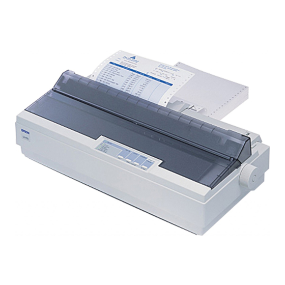
Printer Features The FX-870/1170 combines advanced firmware, reliability, and affordability in a single light-weight unit. The major features of this printer are: Upward compatibility with the FX-850/1050 and the FX-86e/286e 380 cps (high-speed draft for both 80- and 136-column models) 285 cps (draft pica), 342 cps (draft elite) Advanced paper handling Continuous paper... - Page 14 Printer Features 80-column model 136-column model Figure 1-1. External View of the FX-870/1170 Epson FX-870/1170...
-
Page 15: Options
Roll paper holder (only for 80-column model) #8310 Hardware Specifications Printing Method Impact dot Printing method: matrix (diameter 0.29 mm) Pin configuration: 9 wires wire #’ & 2+--- 0.35 mm (l/72”) 3 ‘----___ Figure 1-2. Pin Configuration Epson M-870/1 170... -
Page 16: Paper Handling
Fanfold paper 55 (3.0) 45 (3.7) Single sheet (manual) 48 (3.5) 55 (3.0) Cut sheet (CSF) Thin paper is less than or equal to 0.007 inches (0.18 mm). Thin: Thick: Thick paper is more than 0.007 inches (0.18 mm). Epson FX-8700170... -
Page 17: Precautions For Paper Handling
Remove any slack in the paper between the platen and the pu11 tractor. Precisely adjust the horizontal position of the pull tractor and push tractor. Multi-part paper must be carbonless. Do not perform reverse feeds greater than l/6”. Do not perform reverse feeds after the paper end has been detected. Epson FX-870/1170... -
Page 18: Paper Specifications
Up to 11.7” (297 mm) 80-column Up to 14.3” (364 mm) 136~column Quality Carbonless duplicating paper Thickness 0.0047-0.0086” (0.12-0.22 mm) Weight 12-15 lb (34-50 kg) (40-58 g/m*) - each Copies 4 sheets (1 original + 3 copies) maximum Epson FX-870/1170... -
Page 19: Table 1-6. Specifications For Labels
3. Labels should be used with the pull tractor (front, bottom) or the front push tractor. 4. Do not perform reverse feeds at any time (including by hand). 5. Remove labels from the paper path when not in use. 6. Label printing is possible only at normal temperature and humidity levels. Epson FX-87011170... -
Page 20: Printable Area
3.0 mm (0.12”) or more (80-column). Note: Paper feed accuracy cannot be assured within 0.94” (24 mm) from the bottom edge of the paper (for top insertion) or from within 1.9” (48.5 mm) from the bottom edge of the paper (for front insertion). FX-8700170 Epson... -
Page 21: Figure 1-4. Printable Area For Continuous Paper
25 mm (1 ,O”) or more when the paper width is lo” (254 mm) (80 columns). 13 mm (0.51”) or more when the paper width is 4” to 14.87” (101 mm to 377.8 mm). 25 mm or more when the paper width is 15” to 16” (381 mm to 406 mm) (136 columns). FX-870/1170 Epson... -
Page 22: Ribbon Cartridge
Printer Features Roll paper (80-column model only) 216 2 3 mm (8.5 2 0.12”) top insertion Printable Area WXYZ WXYZ Figure Printable Area for Roll Paper 1-5. *I 0.12” (3.0 mm) or more Note: Paper feed accuracy cannot be assured within 24 mm (0.94”) from the bottom edge of the paper (top insertion only). -
Page 23: Electrical Specifications
MCBF (MCBF: Mean Cycles Between Failures) MTBF (expected value) 4000 power on hours (duty cycle 25%) (80~column) 6000 power on hours (duty cycle 25%) (136-column) (MTBF: Mean Time Between Failures) 100 million characters (14 dots/character) Printhead Life 1-11 Epson FX-870/1170... -
Page 24: Firmware Specifications
2.54 (10 cpi) cpi) 1.48 (17 Condensed 1.05 Elite 2.11‘ (12 cpi) Condensed elite 0.85 1.27 (20 cpi) Table l-11. Printable Columns Type of letters Printable columns [cpi] 80-column model 136-column model Pica Condensed Elite Condensed elite 1-12 Epson FX-8700170... -
Page 25: Interfaces
Controlled by external STROBE pulse. Handshaking Controlled by ACKNLG and BUSY signals. Logic level TTL-compatible Connector plug 57-30360 (Amphenol) or equivalent It is recommended that the interface cable be as short as possible ( 10 feet or 3 meters, maximum). Epson FX-870/1170 1-13... -
Page 26: Figure 1-6. Data Transmission Timing
BUSY A HIGH signal indicates that the printer cannot receive more data. The signal becomes HIGH in the following cases: 1. During data entry 2. During input buffer full 3. During printer error status Epson FX-870/1170 1-14... - Page 27 2. Return means twisted pair return and is to be connected at signal ground level. 3. Be sure to use a twisted-pair cable for each signal, and always complete the connection on the return side. To prevent noise effectively, these cables 1-15 Epson FX-870/1170...
-
Page 28: Optional Interfaces
Table 1-14. Optional Interfaces Catalog W Interface C823051 Serial I/F card (Type B) C823071 32KB intelligent serial I/F card (Type B) C823101 32KB intelligent parallel I/F card (Type B) C823141 Coax interface (Type B) C823151 Twinax interface (Type B) 1-16 FX-870/1170 Epson... -
Page 29: Control Panel
1 second advances the paper to the next top-of-form (TOF) position. When there is no paper in the paper path: Loads continuous paper inserted in the push tractor or cut sheets in the CSF after the printer has detected the paper out. 1-17 Epson FX-870/1170... -
Page 30: Micro Feed Function
The adjustedloading and tear-off positions are stored in non-volatile memory (except for the position of cut sheets loadedby manual insertion). You can endmicro feedmode by pressing the FONT button again. The printer exits this mode automatically when any data arrives from the host computer. 1-18 Epson FX-870/1170... -
Page 31: Bin Selection For The Cut Sheet Feeder
All indicators Error Blinking simultaneously Fatal error Blinking simultaneously very quickly Incorrect RAM Blinking sequentially in the clockwise direction High voltage error All on Low vottage error Blinking in the counter-clockwise direction Head thermistor open circuit error Epson FX-870/1170 1-19... -
Page 32: Default Settings
BLINKS FAST BLINKS No skip Skip over perforation Skip 1 inch BLINKS Zero face BLINKS Auto tear-off BLINKS BLINKS Auto LF with CR Note: The factory setting is that the READY LED is OFF for all features. 1-20 Epson FX-870/1170... -
Page 33: Table 1-17. Group 2 Features (Esc/P Mode)
BRASCI I BLINK Abicomp Note: When the character table PCxxx is selected, that is assigned as the table selected by the,ESC tl command. Then ESC tl and ESC 6 are set as defaults. (Codes 80-9FH are printable characters.) Epson FX-870/1170 1-21... -
Page 34: Self-Test
Press PAPER FEED while turning on the printer to put it in self-test mode. To stop the self-test, turn off the printer. (The control panel is still operational in self-test mode for paper handling and font selection.) When pages are printed the cut- from 1-22 Epson FX-870/1170... -
Page 35: Hexadecimal Dump
If a received code is not a printable ASCII character, the printer prints a period (.) in the ASCII column. See Tables 3-10 and 3- 11 for a hex listing of the commands acceptable to this printer. Figure Hexadecimal Dump Printout 1-9. 1-23 Epson FX-870/1170... -
Page 36: Paper-Out Detection
. Automatic cut-sheet loading and ejection with the cut-sheet feeder Move the release lever to the FRICTION position, and load a stack of paper into the cut-sheet feeder hopper. Pressing PAPER FEED loads the sheet to the top-of-form 1-24 Epson FX-870/1170... -
Page 37: Adjust Lever Operation
0.0072 - 0.01 inches (0.18 - 0.25 mm) 3 (5th step) 0.0104 - 0.0128 inches (0.26 - 0.32 mm) Note: If printing density is light, set the platen gap adjust lever position one step closer. Position 1 (3rd step) Lever Figure l-10. Lever Positions Epson FX-870/1170 1-25... -
Page 38: Printer Initialization
Receipt of a reset (ESC Q) software command . Receipt of a page length command (ESC C) Note: The CMREQ signal goes LOW when the command request is sent from the optional card to the system. main Epson FX-87CY1170 1-26... -
Page 39: Buzzer
The adjusted value set with micro feed Micro feed is the same as the factory setting value (loading position or tear-off position). - . . . (continuously until button is released) The micro feed value has reached its upper or lower limit. 1-27 Epson FX-870/1170... -
Page 40: Main Components
C076 PSB board assembly Printer mechanism Housing assembly The following figure shows the main components of the FX-870/1170. Platen Gap Adjust Lever Release Lever B Board Assembly IN Board Assembly Pril iter Mechanism Figure 1-11. Main Components Epson FX-870/1170 1-28... - Page 41 PSRAM, a MASK ROM, motor drivers, and head drive transistors. PF MOTOR DRIVER TM,p,), CTRr”.“’ ,,DAld-lfil-l CR MOTOR E2PROM 1” o”-+q / I; ; M HEAD DRIVE GAiE ARRAY E05A66YA TRANSISTORS Figure 1-12. CO94 MAIN Board Assembly (Main Control Circuit Board) 1-29 Epson FX-870/1170...
-
Page 42: C094 Pnl Board Assembly (Control Panel Circuit Board)
CO76 PSB Board Assembly (Power Supply Circuit Board) This board is composed of an input filter circuit, a transforming circuit, a switching regulator circuit, a rectifying circuit, a smoothing circuit, and various protecting circuits. Figure PSB Board Assembly 1-14. CO76 (Power Supply Circuit Board) Epson FX-87011170 1-30... -
Page 43: Printer Mechanism
The printer mechanism consists of a g-pin impact dot head, a carriage mechanism, a carriage motor, a paper feed mechanism, a paper feed motor, a ribbon feed mechanism, and various sensors. 136-column model 80-column model Figure l-16. Printer Mechanism 1-31 Epson FX-870/1170... -
Page 44: Housing Assembly
Printer Feature8 Housing Assembly The printer mechanism and all the boards are contained in a housing assembly that consists of the upper case and the lower case. Figure 1-16. Housing Assembly 1-32 Epson FX-870/1170... -
Page 45: Commonly Asked Questions And Answers
If the program I am running does not list the FX-870 or FX-1170 as a printer selection, what other printer can I select in my software? Acceptable driver selections for Epson mode are listed below in order of preference: FX-850 FX- 1050 . - Page 46 The FX-870 and FX-1170 have the most commonly used interface port: Centronics parallel The printer also has an additional slot for an Epson Type B interface. 10. Q. is the size of the input buffer for the built-in parallel interface?
- Page 47 A. No. AI1 default settings are made from the control panel and stored to the E2PROM. (For more information on setting the defaults, see page l-20.) 21. Q. What is the decibel level for the FX-870/1170? A. 55 dB(A). 1-35 Epson FX-870/1170...
- Page 48 25-Pin Computer Connector ..........Epson FX-870/1170...
-
Page 49: Site Requirements
Moves the carriage back and forth until it finds the home position. Lights control panel LEDs. If the printer cannot complete this sequence successfully, refer to Chapter 3, Troubleshooting. Otherwise, turn the printer off, and perform the self-test. Epson FX-870/1170... -
Page 50: Running The Self-Test
25-pin to Spin Serlal Cable Printer Computer side Sick 3 RXD 3 TXD +5 SGND *6 CTS 7 SGND. ,8 DCD 20 DTR Figure 2-1. Serial Cable Configuration to a O-Pin Computer Connector Epson FX-870/1170... -
Page 51: Checking The Printer With The Computer
In this command, n represents the port you are sending data through (typically LPTl or LPTB) and P specifies unlimited retries for time-out errors. The computer will respond with the message: Resident portion of MODE loaded Infinite retry on parallel printer time-out Epson FX-870/1170... -
Page 52: Tips To Increase Printer Life
Although the printhead has a built-in thermistor to protect it, if the printer overheats repeatedly, it can result in printer failure. Use only ribbons recommended by Epson for this printer, and do not re-ink ribbons. The ink in the Epson-recommended ribbons for this product is especially formulated with a lubricant that printhead last longer. - Page 53 Error Codes ................Table 3-7. Symptoms and Flowchart References ......... 3-6 Table 3-8. Identifying Serial Communications Errors ....... 3-7 Table 3-9. Table 3-10. Hex Codes for ESC/P Commands ........3-21 Table 3-11. Hex Codes for IBM Commands ......... 3-23 Epson FX-870/1170...
-
Page 54: Test Points
Troubleshooting 3 The information in this section can help you identify causes of printer problems and test the printer to isolate the part that needs to be replaced. The chapter also contains illustrations showing connector locations and sensor locations. Once you have read this chapter to determine what tests you need to run on the printer, see Chapter 4 for instructions on how to disassemble the printer. - Page 55 Troubleshooting Table 3-2. Sensor Test Points Test Method Sensor Connector (Set Meter to Ohms. Check with Printer Power Off.) Meter Reading Number Release Lever Place one lead on each pin. Change the release Meter should toggle between open and short. lever position.
- Page 56 Troubleshooting [ T E R M I N A L A S S I G N M E N T ] #8 0 #I 7 0 #6 0 #I 5 0. Note: #4 0 The printhead is #3 0 upside down in #2 0 this illustration.
- Page 57 Emitter and base are marked on board. Check from base to collector, from base to * 20%. Not open and not shorted between emitter, and from emitter to collector. base and collector and base and emitter. Reverse leads and test again. Epson FX-870/1170...
-
Page 58: Error Codes
The power supply voltage is abnormal. Use All indicators are on. Low-voltage error flowchart 1 in this chapter to isolate the problem. Note: In the table above, each represents one beep. See Table 1-21 for information on non-error buzzer functions. FX-870/1170 Epson... -
Page 59: Problem Isolation
Troubleshooting Problem Isolation Most printer problems can be corrected by replacing the defective unit. First, identify the problem from the symptoms you observe using the table below. Then, follow the instructions in the corresponding flowchartto correct the problem. Table 3-8. Symptoms and Flowchart References Flowchart or Solution Symptom... -
Page 60: Serial Communications Errors
MODE command at the MS-DOS prompt to match these settings. For instance, if the serial interface card’s switches are in the factory setting, type: MODE=COMn:9600,N,8,1 ,P (“n” is the number of the COM port you are using.) Epson FX-87011170... - Page 61 MODE command from the MS-DOS prompt. For instance, if the serial interface card’s switches are in the factory setting, type: MODE=COMn:9600,N,8,1 ,P (“n” is the number of the COM port you are using.) Epson FX-870/1170...
- Page 62 Troubleshooting Chart 1. Printer Dead at Power On START Use correct AC v o l t a g e . (No fluctuation from AC range shown a t l e f t i s permitted. board. Dower on, does the new Measure the VP I (+35 V) at oin 10 I (+35 V) at pin 10...
- Page 63 ? board. Check motors and printhead. (If shorted, use Tables 3-5 and 3-6 to check drivers on C994 MAIN board, and if bad, replace main board at same time. 1 ” board. 3-10 Epson FX-870/1170...
- Page 64 Troubleshooting Chart 2. Carriage Does Not Move or Moves Abnormally kcuro t h r on the CO94 U&IN connmtors. Manually wow the Check the gears. timing belt. and belt pulley for war, brmkagr, and Coralgn objects. Replace parts and lubrlcatr as nerdad. (km Chapter 5.1 Rapl8ca the Cg94 MAIN board.
-
Page 65: Troubleshooting
Troubleshooting Chart 3. Paper Does Not Feed or Feeds Abnormally START / \No TY*s No / roslstanca o f tha PF motor. l /- 3 I s I t 63 Replace P F motor. I f my coil Is shortrd. use Table 3-6 to Cast PF drlvors on the CW4 WIN board. - Page 66 I f a n y prlnthmd pin I s shortrd. use Tablo 3-5 t o chack drlwrs QZ - Q13 o n tha uln bawd, and I f shorted. raplace at t h e sm tlm 8s the printhead. 3-13 Epson FX-870/1170...
- Page 67 See Figure 6-21 (page 6-18). does ribbon Check gearing for broken or wore gears or foreign objects stuck In the gears. Repface eny gears necessmy. Lubricate as necessary. (See Chapter 5.1 And make sure gears are turning smoothly. 3-14 Epson FX-87011170...
- Page 68 Troubleshooting Chart 6. Data fhm Host is Printed Incorrectly Run self-tart. (Turn on prlntor *hIlo holding down the PAPER FEED button. 1 I f self-tart I s g8rbl.d. t h 8 problr I s with the RDN or C194 RAIN bo8rd. Chrck daf8UltS shown i n t h e s e l f - t e s t .
- Page 69 Troubleshooting Chart 7. Page Length/Margins Incorrect Run self-test and chSck t h e p r i n t e r ’ s drf8ult s e t t i n g s 8gainst the settings In your 8pplic8- t l o n SOftW8rS. p r i n t e r .
- Page 70 Iabolod. P u t a piace o f tape over p i n 14 to block thr sIgnal f r a the p r i n t e r . 3-17 Epson FX-870/i 170...
-
Page 71: Connector Locations
Troubleshooting Connector Locations The layout diagram below shows the positions of connectors on the C094 MAIN board. ‘R\\ / II’ PE Rear’ Figure 3-2. Connector Locations Epson FX-870/1170 3-18... -
Page 72: Sensor Locations
Troubleshooting Sensor Locations The illustrations below show the locations of sensors in the printer mechanism. Figure 3-3. Release Sensor Figure 3-4. Home Position Sensor E p s o n FX-870/1170 3-19... -
Page 73: Figure 1-15. Printer Mechanism
Troubleshooting Printer Mechanism Figure 3-5. Platen Gap Sensor Rear Paper Guide Assembly Figure 3-6. Front and Rear PE Sensors 3-20 Epson FX-870/1170... -
Page 74: Hex Quick Reference Table For Esc/P Commands
Troubleshooting Hex Quick Reference Table for ESC/P Commands Use the table below as an aid to read printer hex dumps. This table is for quick reference only. The user’s guide contains a detailed description of the control codes. Table 3-10. Hex. Codes for ESC/P Commands Command ASCII Hex. - Page 75 ESC I n Set left margin E S C 1 1 0 Turn proportional mode on/off Turn half-speed mode on/off ESC s l/O ESCtn Select character table ESCwl/O Turn double-height mode on/off ESCxllO Select NLQldraft Delete character Epson FX-87011170 3-22...
-
Page 76: Hex Quick Reference Table For Ibm Commands
ESC F Select double-strike mode ESC G Cancel double-strike mode ESC H Select font ESCln ESCJn Perform line feed of n/216 inch Select single-density graphics mode ESC K nl n2 ESC L nl n2 Select double-density graphics mode Epson FX-87011170 3-23... - Page 77 Troubleshooting Table 3-11. Hex. Codes for IBM Commands (Continued) Command Hex. Dec. ASCII Set skip over perforation ESCNn ESC 0 Cancel skip over perforation Turn proportional mode on/off ESC P l/O Deselect printer ESCQn ESC R Reset all tabs ESC S l/O Select subscript/superscript mode Cancel subscript/superscript mode ESC T...
- Page 78 Figure 4-7. Removing the Printer Mechanism ........4-9 Figure 4-8. Removing the Platen Assembly ........4-10 Figure 4-9. Removing the Rear Frame Assembly ......4-11 Figure 4-10. Removing the CR Motor Assembly ......... 4-12 Figure 4-11. Positioning the CR Motor Assembly ....... 4-12 Epson FX-870/1170...
- Page 79 Table 4-1. Recommended Tools ............Equipment Required for Maintenance ......4-1 Table 4-2. Inspection Checklist for Repaired Printer ......4-2 Table 4-3. Abbreviations Used for Screws ......... 4-3 Table 4-4. Screw Types and Abbreviations ........4-3 Table 4-5. Epson FX-870/1170 4-ii...
-
Page 80: Precautions
Disassembly and Assembly 4 This section provides information you need to know to disassemble or assemble the printer. Precautions Read the precautions below before you disassemble or assemble the printer. WARNING Before disassembling, assembling, or adjusting the printer, disconnect the power supply cable from the AC power outlet. -
Page 81: Service Checks After Repair
Disassembly and Assembly Service Checks After Repair Before you send the printer back to the customer, fill in the checklist in Table 4-3 note the current state of the components. This checklist facilitates servicing and shipping. Table 4-3. Inspection Checklist for Repaired Printer Component QmwY items to Check... -
Page 82: Screw Specifications
Washer (assembled) Side .Cross-recessed head 1. Bind 1 ._Plain washer 1 .tjormal o~ooE 2. S-tight !.Slotted head (with Notch) 2.Qutside toothed /- \ lock washer 2._Pan --.. __ :’ oT=d 3.cup 4. Iapping 3.Spring washer OQ$+ 4. Iruss Epson FX-870/1170... -
Page 83: Notes For Unit Removal And Installation
Tractor Unit PAGE 4-19 PAGE 4-15 PAGE 4-20 Removing the Disassembling the Removing the Removing tfk FRONT AND REAR PF GEAR TRAIN RD ASSEMBLY CARRIAGE GUIDE RELEASE PE SENSORS SENSOR ASSEMBLY Figure 4-1. Flowchart for Disassembling the Printer Epson FX-870/1170... -
Page 84: Items To Remove Before Disassembling The Printer
Figure 4-2. Removing the Paper Guide Assembly paper eject cover and the tractor unit by pushing and releasing the hooks Note: Remove the at both sides. When remounting them, be sure to snap these hooks on the projecting parts. Epson FX-870/i 170... -
Page 85: Removing The Panel Unit
Figure 4-3. Removing the Panel Unit Assembly Note The FFC cable must be connected properly, as shown below. Plain Face FFC Cable Face with exposed terminals at the end of the cable. Figure 4-4. Connecting the FFC Cable to the Panel Unit Epson FX-870/1170... -
Page 86: Removing The Printhead
and Assembly Disassembly Removing the Printhead Remove the paper guide assembly, ribbon, top cover, front cover, paper eject cover, and tractor unit. (See page 4-5.) Remove the two CBS (M3x8) screws from the printhead, lift the printhead up, and remove the FFC cable. -
Page 87: Removing The Upper Housing Assembly
Disassembly and Assembly Removing the Upper Housing Assembly Remove the paper guide assembly, ribbon, top cover, front cover, paper eject cover, and tractor unit. (See page 4-5.) Remove the panel unit. (See page 4-6.) Remove the four CBC (M4x15) screws securing the upper housing assembly. (There are only three screws in the 80-column printer.) Use a small screwdriver to push the two hooks through the cutouts, located on the front cover, to disengage the hooks from the plates. -
Page 88: Removing The Printer Mechanism
Disassembly and Assembly Removing the Printer Mechanism Remove the paper guide assembly, ribbon, top cover, front cover, paper eject cover, and tractor unit. (See page 4-5.) Remove the panel unit. (See page 4-6.) Remove the upper housing assembly. (See page 4-8.) Remove the four CBB (M4x12) screws securing the printer mechanism. -
Page 89: Removing The Platen Assembly
Remove the platen knob. Remove the ribbon mask by pushing the two clips. Slide the platen assembly and remove it. CBS (M3X8) Platen Knob Platen Cover Platen Shaft Holder Figure 4-8. Removing the Platen Assembly Epson FX-870/1170 4-10... -
Page 90: Removing The Rear Frame Assembly
Push the clip on the back of the rear frame assembly. Slide out the rear frame. Hexagon Nut frfd??iA ” Outside Toothed Lock Washer CBS (M3X8) Parallelism Adjustment Bushing Rear Paper Guide Assembly Figure 4-9. Removing the Rear Frame Assembly 4-11 Epson FX-870/1170... -
Page 91: Removing The Cr Motor Assembly
/ LCBN W3X8) Figure 4-10. Removing the CR Motor Assembly Assembly Note Position the CR motor assembly on the belt tension plate correctly as shown below. Cable CR Motor Figure 4-11. Positioning the CR Motor Assembly 4-12 Epson FX-870/1170... -
Page 92: Removing The Pf Motor Assembly
Disassembly and Assembty Removing the PF Motor Assembly Remove the paper guide assembly, ribbon, top cover, front cover, paper eject cover, and tractor unit. (See page 4-5.) Remove the panel unit. (See page 4-6.) Remove the upper housing assembly. (See page 4-8.) the printer mechanism. -
Page 93: Disassembling The Pf Gear Train
Disassembly and Assembly Disassembling the PF Gear Train the paper guide assembly, top cover, front cover, paper eject cover, and tractor unit. Remove (See page 4-5.) Remove the panel unit. (See page 4-6.) Remove the upper housing assembly. (See page 48.) Remove the printer mechanism. - Page 94 Disassembly and Assembly Removing the Carriage Assembly Remove the paper guide assembly, ribbon, top cover, front cover, paper eject cover, and tractor unit, (See page 4-5.) Remove the panel unit. (See page 4-6.) Remove the printhead. (See page 4-7.) Remove the upper housing assembly. (See page 4-8.) Remove the printer mechanism.
- Page 95 When attaching the timing belt to the carriage assembly, secure the timing belt using the 1eR and right clips of the carriage assembly as shown below. Make sure there is no slack in the timing belt. Clip Timing Figure 4-16. Attaching the Timing Belt Epson FX-870/1170 4-16...
-
Page 96: Removing The Carriage Guide Assembly
Disengage the timing belt from the CR motor assembly. (See page 4-12.) Remove the carriage guide assembly. (See page 4-15.) Remove the CBC (M3x8) screw and the CBB (M3x8) screw securing the RD assembly. Remove the RD assembly. CBC (M3X8) RD Assembly Figure 4-17. Removing the RD Assembly Epson FX-870/1170 4-17... -
Page 97: Removing The Home Position (Hp) Sensor
Remove the printer mechanism. (See page 4-9.) the two clips of the PG sensor attached to the left frame of the printer mechanism. Remove Remove the sensor. Disconnect the PG lead from the PG sensor. Printer Mechanism Figure 4-19. Removing the PG Sensor Epson FX-870/1170 4-18... -
Page 98: Removing The Front And Rear Paper End (Pe) Sensors
Remove the rear frame assembly. (See page 4-11.) the clip for each PE sensor mounted on the rear paper guide assembly. Remove the Remove front PE sensor and rear PE sensor. Remove the lead from each PE sensor. Figure 4-20. Removing the PE Sensors m-am1 Epson 4-19... -
Page 99: Removing The Release Sensor
Remove the rear frame assembly. (See page 4-11.) Remove the two clips for the release sensor mounted on the rear paper guide assembly. Remove the release sensor. Disconnect the release lead from the sensor. Release Sensor Figure 4-21. Removing the Release Sensor Epson FX-870/1170 4-20... -
Page 100: Arranging The Cables
Disassembly and Assembly Arranging the Cables When you assemble the printer, arrange the cables as shown in Figure 4-22. Printer Mechanism (Bottom) Figure 4-22. Arranging the Cables E p s o n F X - 8 7 0 0 1 7 0 4-21... -
Page 101: Disassembling The Tractor Unit
Tractor Guide Shaft Tractor Shaft Figure 4-23. Disassembling the Tractor Unit Assembly Note When reassembling the tractor unit, be sure to snap the clips for cog (17) onto the tractor shaft. Clips Figure 4-24. Position of the Cog 4-22 Epson FX-870/1170... -
Page 102: Removing The C094 Main Board Assembly
Disassembly and Assembly Removing the C094 MAIN Board Assembly Remove the paper guide assembly, ribbon, top cover, front cover, paper eject cover, and tractor unit. (See page 4-5.) panel unit. (See page 4-6.) Remove the the upper housing assembly. (See page 4-8.) Remove Remove the printer mechanism. -
Page 103: Removing The C076 Psb Board Assembly
Removing the C076 PSB Board Assembly NOTE To remove the C076 PSB board assembly for replacement, you must use a special extractor tool, available from Epson Parts Order Services. After obtaining the special tool shown, follow the procedure below. OneWai (Rivet Head) Screw Figure 4-26. - Page 104 Disassembly and Assembly CBC (M3X8) CBB (M3X12) Assembly C076 PSB Board Figure 4-27. Removing the C076 PSB Board Assembly 4-25 Epson FX-870/1170...
-
Page 105: Bidirectional Alignment Adjustment
Lubrication Points ............5-6 Table 5-2. Epson FX-870/1170... -
Page 106: Chapter 5 Adjustments, Maintenance, And Lubrication
Move the release lever back to the FRICTION setting. Move the carriage until the edge of the printhead is at the fifth column print position. Use a box driver (7 to rotate the parallelism adjustment bushing on the left frame of the printer mechanism. Epson FX-870/1170... - Page 107 0.40 mm gauge. If this is not the case, go back to step 8. 14. Remove the printhead, install the ribbon mask, replace the printhead, and install the printer mechanism back in the case. Epson FX-870/1170...
-
Page 108: Bidirectional Alignment Adjustment
Also, the correction value must be written to each E2PROM, and it must be rewritten after each adjustment. Bidirectional Alignment Adjustment Procedure The FX-870/1170 has a built-in bidirectional adjustment program. Follow the steps on the next page to adjust the bidirectional alignment. Epson FX-870/1170... -
Page 109: Lubrication
(See Figure 5-4.) If the vertical lines are well aligned, go to step 7. Otherwise, go to step 6. Follow the instructions in step 3. Turn off the printer’s power. //I/iiI/ii/I//ii//l///!i/il/liiliilliii/iiiiiiiiiiliiiiIiii/iii/li Figure 5-4. Bidirectional Alignment Adjustment (Draft Mode) Figure 5-5. Bidirectional Alignment Adjustment (NLQ mode) Epson FX-870/1170... -
Page 110: Preventive Maintenance
Disconnect the printer from the external AC power source before performing maintenance Lubrication Epson recommends that the printer be lubricated at the points shown in Figure 5-2. Table 5-2 lists each lubrication point and its recommended lubricant. All the lubricants have been tested extensively and found to comply with the requirements of this printer. - Page 111 The shaft end of the drive roller assembly G-26 The ribbon drive gear train G-26 The oil pad in the carriage assembly The cam surface of the tractor clutch cam G-26 The cam end of spur gear 34.5 G-26 Epson FX-870/1170...
- Page 113 Entrance ................Epson FX-870/1170...
- Page 114 Ribbon Advance Gear Linkage ......... 6-18 Table 6-2. Power Supply Input Voltage and Fuse Rating....6-19 Table 6-3. Power Supply Output Voltages and Applications .... 6-19 Table 6-4. Functions of Main Components of C094 MAIN ....6-24 Table 6-5. Epson FX-870/1170 6-ii...
- Page 115 Principles of Operation Table 6-6. Carriage Motor Drive Modes ..........6-27 Repairing the C076 PSB Board Assembly ......6-31 Table 6-7. Table 6-8. Repairing the C094 MAIN Board Assembly ..... 6-34 Epson FX-870/1170 6-iii...
-
Page 116: Printer Mechanism Operation
2. This induced force causes the plate to approach the coil rod, and the associated dot wire is rapidly ejected to impact on the platen. 3. The dot wire presses the ink ribbon up against the paper as it hits the platen, and in this way, prints a dot on the paper. Epson FX-870/1170... - Page 117 The CPU detects the voltage change and stops printing until the head temperature cools. The printhead is also used as a buzzer. Head driving coils move all the dot wires back and forth without impacting the platen, so that the wires vibrate. The vibrating dot wires sound like a buzzer. Epson FX-870/1170...
-
Page 118: Carriage Mechanism
The carriage (CR) motor, a stepping motor, drives the timing belt, which moves the carriage. The home position (HP) sensor detects the home position of the carriage. Timing Belt Pulley CR Motor Figure 6-2. Carriage Operation Epson FX-870/1170... -
Page 119: Platen Gap Adjustment
The platen gap (PG) sensor detects the position of the adjust lever. The correct platen gap is 0.38 mm f 0.02 mm with the adjust lever set to position 0. Platen Platen Gap Adjustment / I9 PO Sensor Figure 6-3. Platen Gap Adjust Lever Epson FX-870/1170... -
Page 120: Paper Handling Mechanisms
Table 6-1 lists which paper paths can be used with each paper feed method. Table 6-1. Paper Feed Methods and Paper Entrances Paper Entrance Paper Feed Method Rear Front Bottom Friction Push tractor Pull tractor Push-pull tractor Epson FX-870/I 170... -
Page 121: Paper Advance Mechanisms
You can release this pressure and free the paper by setting the release lever to the tractor feed position. Paper (Cut Sheet) /Tractor Reduction Gear PF Motor Pinion Gear Paper Advance Reduction Gear 6F Motor Figure 6-4. Friction Advance Operation Using the Top Paper Entrance Epson FX-870/I 170... - Page 122 Paper Tension Roller Push Tractor l \ Tractor Gear Tractor Reduction Gear , P F Motor Pinion Gear Paper Tension Roller Gear 6F Motor P/aper Advance Reduction Gear Figure 6-5. Push Tractor Operation Using the Rear Paper Entrance Epson FX-870/I 170...
- Page 123 Pthcipk of Operation Paper (Continuous) Paper Tension Roller Paper Tension Roller Gear Platen Gear PF Motor P&h Tractor ‘Push Tractor Gear Figure 6-6. Push Tractor Operation Using the Front Paper Entrance Epson FX-870/I 170...
- Page 124 Figure 6-7 illustrates pull tractor operation when the paper is fed through the bottom paper entrance. Paper (Continuous1 II Tractor Gear Reduction Gear Paper Drive PF Motor Paper Advance Reduction Gear Paper Drive Roller Gea Platen Gear Figure 6-7. Pull Tractor Operation Using the Bottom Paper Entrance Epson FX-870/I 170...
- Page 125 Paper (Continuous) Pull Tractor Push Tractor Push Tractor Gear Tractor Reduction Gear ,PF Motor Pinion Gear Pull Tractor Gear fiF Motor Paper Advance Reduction Gear Figure 6-8. Push-pull Tractor Operation Using the Rear Paper Entrance Epson FX-870/1170 ’ 6-10...
- Page 126 Paper Drive Roller ctor Reduction Gear Gear PF Motor Pinion PF Motor PaDer Advance Reduction Gear \’ Platen Gear Paper Drive Roller Gear ush Tractor Gear Push Tractor Figure 6-9. Push-pull Tractor Operation Using the Front Paper Entrance 6-11 Epson FX-870/1170...
-
Page 127: The Release Lever
Figure 6-11 shows the function of each release lever setting. Release Lever Paper Guide Rollers Right Frame Release Sensor Release Shaft Figure 6-10. Release Lever Front pkh-tractor Release Lever or Rear push-tractor Figure 6-11. Release Lever Setting Functions 6-12 Epson FX-870/1170... -
Page 128: Paper Paths
When the top entrance is used, the rear PE sensor senses when paper is out. Paper (Cut Sheet) Paper Tension Roller Printhead Paper Guide Rollers Figure 6-12. Paper Path for Friction Feeding Using the Top Entrance Epson FX-8700 170 6-13... - Page 129 Paper Tension Roller Prlnth Pap& Guide Rollers Figure 6-13. Paper Path for Push Tractor Feeding Using the Rear Entrance Paper (Continuous) Printhead Paper &ide Rollers Figure 6-14. Paper Path for Pull Tractor Feeding Using the Rear Entrance 6-14 Epson FX-870/1170...
- Page 130 When the bottom entrance is used, the front PE sensor senses when paper is out. Paper (Continuous) Tractor Paper Front PE Sensor Lower Paper Guide Roller Paper Figure 6-16. Path for Pull Tractor Feeding Using the Bottom Entrance Epson FX-870/1170 6-15...
- Page 131 Lower Paper Guide Roller Figure 6-17. Paper Path for Friction Feeding Using the Front Entrance Paper (Continuous), Paper Tension Roller Paper ower Paper Guide Roller Push Tractor Figure 6-18. Paper Path for Push Tractor Feeding Using the Front Entrance Epson FX-870/1170 6-16...
- Page 132 Lower Paper Guide Roller Figure 6-19. Paper Path for Pull Tractor Feeding Using the Front Entrance Paper Drive Roller Tower Paper Guide Roller Front PE Sensor Push Tractor Figure 6-20. Paper Path for Push-pull Tractor Feeding Using the Front Entrance Epson FX-870/1170 6-17...
-
Page 133: Ribbon Advance Mechanism
The ribbon mask prevents the ribbon from brushing against the paper. Ribbon Advance Roller, Ink Ribbon Ribbon Pressure I’ Mask .ake Gear (21, Ribbon Driving Gear Figure 6-21. Ribbon Advance Mechanism 6-18 Epson FX-870/1170... -
Page 134: Power Supply Operation
A +5 VDC voltage is generated by feeding the +35 VDC voltage through the +5 VDC power supply circuit, where the +35 VDC is stepped down to a stable +5 VDC voltage. The switching regulator IC containing the overcurrent/overvoltage control circuits performs this function. It controls the +5 VDC line output. Epson FX-87011170 6-19... - Page 135 AC power source. For this reason, you must disconnect the printer fi-om the external AC power source. Unplug the power cable from the AC power outlet before you perform any maintenance work. 6-20 Epson FX-870/1170...
- Page 136 +35 V Line _ P h o t o - + Detector Circuit coupler 2052 +35 V Line Voltage Overload Protection Circuit - Voltage Drop Protection Circuit Power - Switch Figure 6-22. Power Supply Circuit Block Diagram Epson FX-870/1170 6-21...
-
Page 137: Control Circuit Operation
6-23 shows the control circuits in block diagram form. ‘-1 pzG=L MASK E’PROM PSRAM 4K BIT 1M BIT -.* -.- CONTROL PANEL BUlTONS AND LEDS ~i%k%E +6VDC m Data +36VDC Address bus Figure! 6-23. Control Circuit Block Diagram Epson FX-87W1170 6-22... - Page 138 Figure 6-24 shows the data flow from the host computer to the printhead. Data sent the host fkom computer is converted to image data and transmitted to the printhead through the gate array. Host computer Input buffer Image data transfer Gate Array (EOSABGYA) Figure 6-24. Data Flow Epson FX-87W1170 6-23...
- Page 139 The RAM contains the CPU working area and the buffers. E2PROM (XI) The E*PROM is used to store information such as the top-of-form position. UPAl475H (ICl) Drive circuit for PF motor SLA7024M (iC5) Drive circuit for CR motor 6-24 Epson FX-87W1170...
-
Page 140: Reset Circuit
The reset signal is also issued when the INIT signal is sent from the host computer. Figure 6-25 shows the power on reset circuit. GA (IC4) +35VDC +5VDC DISC ROUT 156 l 5 5 I5 ZD2+ gR31 CPU ~IC2ClI I 15 Power On Reset Circuit Figure 6-25. Epson FX-870/1170 6-25... -
Page 141: Sensor Circuits
Figure 6-26 shows the sensor circuit block diagram. CPU (1C) CRHOME PE FRONT PE REAR RELEASE LEVER +35 Voltage Monitor +35 Voltage Monitor +35 v +35 v Head Temperature Head Temperature Vref Vref Vref Vref Figure 6-26. Sensor Circuit Block Diagram 6-26 Epson FX-8700 170... -
Page 142: Carriage Motor Drive Circuit
Table 6-6. Carriage Motor Drive Modes Speed Mode Excitation Phase Characters Printed 4468 Super draft 3840 Super draft copy 3357 Draft 10 cpi 2800 high 2240 duty 1680 5/l 2 1400 high duty 5124 5/12 high I -2 duty FX-870/1170 6-27 Epson... -
Page 143: Paper Feed Motor Drive Circuit
PF motor. Otherwise, a +6 V voltage is supplied through Dl to hold the motor. UPAl476H (ICl) PF MOTOR 4-phase, 48-p PM-type pulse motor 36 VDC i 10% 61 a * 3 fi (per phase) (at 77’ F, 26“ C) Figure 6-28. Paper Feed Motor Drive Circuit Epson 6-28 FX-87W1170... -
Page 144: Printhead Drive Circuit
Figure 6-30 shows the parallel interface circuit. E05A55YA (IC4) CPU (IC2Cl) Parallel I/F DO-7 DINO-7 DATAO-7 DO-7 - - - - - - - - q----------- STROBE ----,,,,A B U S Y + BUSY Figure 6-30. Parallel Interface Circuit Epson FX-870/1170 6-29... -
Page 145: E2Prom Control Circuit
Because the E2PROM is a serial I/O device, the gate array converts the parallel data (sent fiorn the host computer) into serial data. B5A66YA (IC4) CPU (IC2Cl) Data Bus Figure 6-31. EZPROM Control Circuit Epson FX-870/1170 6-30... -
Page 146: Component Repair Information (For Dealers Outside The U.s.)
Measure the resistance of the Tl transformer coils qeplace Tl . coils are open. at pins 3-2, 5-4, 1 O-l 1, and 11-9. Ql is bad. * Check the voltage waveforms at Ql. qeplace Ql . CH1=50V TIME=2ps Epson FX-870/1170... - Page 147 Check the voltage waveforms at Q3. Replace Q3, t35 V line is below PC2 or ZD51 is ICl, PCl, the specified value. bad. PC2 or zD51. Q2 is bad. Check the voltage waveforms at Q2. Replace Q2. Epson FX-870/1170 6-32...
- Page 148 Replace Check the oscillation waveform (IC51 pin 5) and the IC51 is bad. IC51. switching waveform (IC51 pin 8). Replace Q51 or Q52 is Check the switching waveform at Q52 emitter. Q51 or bad. Q52. 6-33 Epson FX-870/1170...
-
Page 149: Repairing The C094 Main Board Assembly
Replace The control Check HIGH/LOW alternation for the IC4. ROM is not signal (IC4 pin 4). selected. Either the Replace IC2 ROM or the or IC3. RAM is defective. Epson PX-870/1170 6-34... - Page 150 IC2Cl. Otherwise, replace CRl. Carriage Replace IC6. IC6 is Check the input signal (pin 5) and the output operation carriage defective. waveform (pin, 8). abnormal. does not operate at all. Epson FX-870/1170 6-35...
- Page 151 A particular at the base head driie the emitter of each transistor. printing dot fails to is normal, abnormal. transistors print. replace the is defective transistor. 4,5, Otherwise, 6, 8, 9, 10, replace IC4. 11, or 12). Epson PX-870/1170 6-36...
- Page 152 Either IC4 or Replace IC4 Incorrect Data is IC5 is or IC5. printing of corrupted defective. data sent when the from the p a r a l l e l host interface is computer. used. Epson FX-87011170 6-37...
-
Page 153: List Of Figures
CN9, Rear PE Sensor (C094 MAIN Board Assembly) ..7-4 Table 7-10. CN12, Control Panel (C094 MAIN Board Assembly)..7-4 Table 7-11. CN13, Carriage Motor (C094 MAIN Board Assembly) ..7-4 Table 7-12. CN14, Power Supply (C094 MAIN Board Assembly)..7-4 Epson FX-870/1170... -
Page 154: Connector Summary
AC IN CO94 MAIN BOARD ASSEMBLY 1 CN4 t 1 CN6 1 C Nl +iiq (CN2k 1 CN13 1 CO76 BOARD ASSEMBLY PF MOTOR ASSEMBLY PRINTER MECHANISM CO94 PNL BOARD ASSEMBLY I Figure 7-1. Cable Connections Epson FX-870/1170... - Page 155 2 ( B l a c k ) PF Motor Assembly Home Position (HP) Sensor 2 ( Y e l l o w ) Printhead Rear PE Sensor CN12 CO94 PNL Board Assembly CN13 CR Motor Assembly CN14 CO76 PSB Board Assembly Epson FX-870/1170...
- Page 156 Data Bus Bit 6 Data Bus Bit 5 Table 7-7. CN7, Home Position Sensor Data Bus Bit 4 (CO64 MAIN Hoard Assembly) Data Bus Bit 3 Data Bus Bit 2 Data Bus Bit 1 Data Bus Blt 0 Epson FX-870/1170...
- Page 157 (CO94 MAIN Board Assembly) IW. l/O Signal Name Function +5 VDC READY READY LED STAT STAT LED ( Not equipped) FONT FONT LED COND ‘CONDENSED LED PAUSE Button PAUSE FONT FONT Button PFEED PAPER FEED Button OPERA OPERATE Button Signal Ground Epson FX-870/1170...
-
Page 158: Circuit Diagrams
A /I/II/II III ,,,, I Il/IIl/II I I I I I I ’ Head /IIm O,‘” Conrrol - Pf Molar Control LE<ER G&P PEFRNT Pf Motor Ower PERAEFI Figure 7-2. C094 MAIN Board Assembly Circuit Diagram (Annotated) Epson FX-870/1170... - Page 159 Reference Materials Figure 73. C094 MAIN Board Assembly Circuit Diagram Epson FX-87CY1170...
- Page 160 Surge Current ProtectIon ct-42 Clrcult t5V DC Reourator ‘-9; FMP-G125 220Op/lKV +35V/O.?A LPZOl-2R5SO +SV/I.OA o.3gs PO. 7 A O.,u,‘AC250V +5V/l.OA tection O.Olu L7OOp/ IKV iV Over I 2.5A,125V X1 : HEAT SINK C076 PSB Power Supply Board C N I IOO-12OVAC...
- Page 161 T’ I P T - 0 ’ Bohm/25C 2200p/lKV 3’ lOK/ Cl2 - - L70pRKV AGOI 33ooun1 5 o v 0.1 u/ACZ%,V 33oou I t - 5 o v a_ C 5 6 (L2) - - 2 2 o o p 1 KV 22”dP ‘-T...
- Page 162 *PAPER FEED t&-----h “’ *SW3 * F O N T o6 ij-L rPAUSE/l-OFF LED3 CONDENSED 1/1 LED2 FONT STATUS LED1 Note: The STATUS LED is not implemented in this model. Figure 7-6. CO94 PNL Board Assembly Circuit Diagram Epson FX-870/1170...
-
Page 163: Circuit Board Component Layouts
PF Motor /CNl PG Sensor cN5\ C N 7 - PE Rear/ !z?Rm PE Front P r i n t h e a d P&iead zeyi EN3”” Drivers Figure 7-7. CO94 MAIN Board Assembly Component Layout 7-10 Epson FX-870/1170... - Page 164 Reference Materials EPS-I I MODEL 1 Figure 7-8. CO76 PSB Board Assembly Component Layout Epson FX-870/1170 7-11...
- Page 165 Sw2 A S S Y 2 0 0 6 1 6 0 0 0 I I CO94 PNL A , --4 CMK- 54x1 Am Note: The STATUS LED is not implemented in this model. Figure 7-9. CO94 PNL Board Assembly Component Layout 7-12 Epson F&870/1 170...
-
Page 166: Outline Drawings
Reference Mater& Outline Drawings ’ Figure 7-10. FX-870 Case Outline Drawing Epson FX-870/1170 7-13... - Page 167 Reference Materials z -- 0 1 - - r-r-=- Figure 7-11. F’X-1170 Case Outline Drawing 7-14 Epson FX-870/1170...
- Page 168 1-1 tear-off 1-20, 1-24 AUTOEXEC.BAT 2-4 base 3-4, 6-36 baud rate 3-8 beeps 1-20, 1-22, 1-27, 3-5 belt driven pulley 6-18 bidirectional adjustment 3-6, 5-3 bidirectional printing 1-12 bin 1-27 selection 1-19 image mode 1-12 rate 3-7 Epson FX-870/1170 Index-1...
- Page 169 1-1, 1-21, 1-22 checklist 4-2 circuit diagrams 7-5 through 7-9 cleaning 5-5 CMREQ 1-26 Coax interface 1-3 codes 3-21 through 3-24 coil 6-1, 6-27 collector 3-4 columns 1-12 COM port 3-7, 3-8 commands ESC/P 3-21,3-22 IBM 3-23,3-24 Index-2 Epson FX-870/1170...
- Page 170 1-35 default setting mode 1-1, 1-24, 3-7 settings 1-20, 1-23, 1-35,3-6 denatured alcohol 5-5 Denmark 1-21 density 1-25 dielectric strength 1-11 diodes 3-4 DIP switch l-l, 3-8 settings 3-7 direct current 6-19 disassembly 4-1 through 4-25 Epson FX-870/1170 Index-3...
- Page 171 1-4, 1-7 fatal error 1-19, 1-27, 3-5 feed 3-12 FET (Ql) 4-24, 6-31 FFC 4-6, 4-7, 4-9, 4-11, 4-13, 4-14 filter circuit 6-19 firmware specifications 1-12 version 1-23 flexible flat cable 4-6, 4-7, 4-9, 4-11, 4-13, 4-14 Index-4 Epson FX-870/1170...
- Page 172 Germany 1-21 graphics 3-8 grease 5-5 ground 2-2,3-1, 3-4 group 1 features 1-20 2 features 1-21 3 features 1-22 handling paper 1-5 handshaking 1-13, 3-8 head cable 3-6, 3-13 drive signal 6-26 drive transistors 3-4, 6-36 hot 1-19 Epson FX-870/1170 Index-5...
- Page 173 1-1, 1-13, 1-15, 1-17, 1-22, 1-24, 1-26,6-24 full 1-14 frequency 1-11 voltage 6-19 installation 4-4 interconnection 7-1 interface 1-3, 1-13, 1-34, 2-1, 3-6, 3-7, 3-8, 6-29,7-3 card l-3, 3-7, 3-8, 4-23 circuit 2-2, 6-29 configuration 2-4 interrupt signal 6-29 isolate 3-1 isolation 3-6 Index-8 Epson FX-87W1170...
- Page 174 3-7 feed 1-18, 1-27 microprocessor 6-22 MODE command 3-7, 3-8, 2-3, 2-4 motor 1-31,3-2, 3-4, 3-6,4-12, 4-13, 6-3, 6-19, 6-22, 6-24, 6-27,6-28, 7-4 drivers 3-4 MTBF 1-11 multi-part 1-5 paper 1-5 multimeter 3-2, 3-3, 3-4, 4-1 Epson FX-870/1170 Index-7...
- Page 175 1-31, 6-1 motor 1-31,3-4,3-6,4-13,6-7,6-19,6-24,6-26,6-28,7-3 drive circuit 6-28 drivers 3-4 guide assembly 4-5 rollers 6-6, 6-12 handling 1-4, 6-5 out 1-17, 1-24, 3-5 park 1-1, 1-19, 1-25 path 1-7, 1-17, 1-35, 6-5, 6-13, 6-14, 6-15, 6-16, 6-17 Index-8 Epson FX-870/1170...
- Page 176 1-24, 3-2, 4-11,5-1,6-4 adjustment 3-6,4-1, 5-1,5-3 sensor 3-20,4-18,6-4, 7-3 platen gear 6-6, 6-7 platen knob 4-10 platen shaft holder 4-10 PNL board 1-28, 1-30,6-22 circuit diagram 7-9 component layout 7-12 port 2-3, 2-4 power 3-1 cable 6-20 Epson FX-870/1170 Index-9...
- Page 177 Index consumption 1-11 on 1-22, 3-6, 3-7, 3-9, 3-10, 6-34 default settings 1-13, 1-22 hours 1-11 reset 6-25 sequence 2-1 outlet 2-1,6-31 supply 1-28, 1-30, 3-1, 3-4, 4-1, 4-4, 4-23, 4-24, 6-19, 6-31 through 6-33, 7-4 voltage 3-5, 3-6 precautions 4-1 preventive maintenance 5-5 primary circuit 3-1, 4-1, 4-4, 6-20, 6-31 print...
- Page 178 3-6, 4-10, 5-1, 5-2, 6-18 pressure roller 6-18 tension 6-18 right frame 4-11 sub frame 4-14 tractor frame 4-22 roll paper 1-3, 1-4, 1-10 rollers 5-5 ROM 3-6, 6-34 Roman 1-18, 1-19 RS-232C 2-2 safety approvals 1-12 Sans serif 1-18, 1-19 Epson FX-870/1170 Index-11...
- Page 179 5-6 stepping motor 6-3, 6-22, 6-28 stop bit 2-4 STROBE pulse 1-13 signal 6-29 sub frame 4-14 sunlight 2-1 supply 3-1 Sweden 1-21 switches 1-1, 3-7, 3-8 switching circuit 6-20 waveform 6-33 symptoms 3-6, 3-7 Index-12 Epson FX-87W1170...
- Page 180 3-4, 6-36 Twinax interface 1-3 twisted pair 1-15, 2-2 Type B 1-34, 2-1, 2-2 U.K. 1-21 unidirectional printing 1-12 unlimited retries 2-3, 2-4, 3-8 upper housing assembly 4-8 ventilation 2-1 vertical lines 5-3 tab 1-26 vibration 1-11, 2-1 Epson FX-8700170 Index-13...
- Page 181 WARNING 4-1, 4-4, 4-24, 3-1 washers 4-3 waveform 6-31, 6-32, 6-33, 6-34, 6-37 weight 1-6, 1-7, 1-8, 2-1, 6-4 width 1-6, 1-7, 1-9 wire 6-1 resetting spring 6-2 wires 1-3 word length 3-8 XON/XOFF 3-8 Zero face 1-20 Index-14 Epson FX-870/1170...
Need help?
Do you have a question about the FX-870 and is the answer not in the manual?
Questions and answers