Table of Contents
Advertisement
Advertisement
Table of Contents

Related Manuals for Asus P8P67 WS REVOLUTION


Summary of Contents for Asus P8P67 WS REVOLUTION
- Page 1 P8P67 WS Revolution...
- Page 2 Product warranty or service will not be extended if: (1) the product is repaired, modified or altered, unless such repair, modification of alteration is authorized in writing by ASUS; or (2) the serial number of the product is defaced or missing.
-
Page 3: Table Of Contents
Welcome! ..................1-1 Package contents ................. 1-1 Special features ................1-2 1.3.1 Product highlights ............1-2 1.3.2 ASUS Workstation Exclusive Features ......1-3 1.3.3 ASUS features ..............1-4 Chapter 2: Hardware information Before you proceed ..............2-1 Motherboard overview ..............2-2 2.2.1... - Page 4 ASUS Drive Xpert ............3-31 Exit menu ..................3-32 3.10 Updating BIOS ................3-33 3.10.1 ASUS Update utility ............3-34 3.10.2 ASUS EZ Flash Utility ........... 3-37 3.10.3 ASUS CrashFree BIOS 3 utility ........3-38 3.10.4 ASUS BIOS Updater ............. 3-39...
- Page 5 Contents Chapter 4: Software support Installing an operating system ........... 4-1 Support DVD information ............4-1 4.2.1 Running the support DVD ..........4-1 4.2.2 Obtaining the software manuals ........4-2 Software information ..............4-3 4.3.1 AI Suite II ................ 4-3 4.3.2 DIGI+ VRM ..............
- Page 6 Contents 5.2.2 Installing two SLI-ready graphics cards ......5-6 5.2.3 Installing three SLI-ready graphics cards ......5-7 5.2.4 Installing the device drivers ..........5-8 5.2.5 Enabling the NVIDIA SLI™ technology ......5-8 ® NVIDIA CUDA™ technology ............ 5-11 ® 5.3.1 Requirements ..............5-11 5.3.2 Installing CUDA-ready graphics cards ......5-11...
-
Page 7: Notices
Canadian Department of Communications. This class B digital apparatus complies with Canadian ICES-003. REACH Complying with the REACH (Registration, Evaluation, Authorization, and Restriction of Chemicals) regulatory framework, we published the chemical substances in our products at ASUS website at http://csr.asus.com/english/ REACH.htm. -
Page 8: Safety Information
Safety information Electrical safety • To prevent electrical shock hazard, disconnect the power cable from the electrical outlet before relocating the system. • When adding or removing devices to or from the system, ensure that the power cables for the devices are unplugged before the signal cables are connected. If possible, disconnect all power cables from the existing system before you add a device. -
Page 9: About This Guide
Refer to the following sources for additional information and for product and software updates. ASUS websites The ASUS website provides updated information on ASUS hardware and software products. Refer to the ASUS contact information. Optional documentation Your product package may include optional documentation, such as warranty flyers, that may have been added by your dealer. -
Page 10: Conventions Used In This Guide
Conventions used in this guide To ensure that you perform certain tasks properly, take note of the following symbols used throughout this manual. DANGER/WARNING: Information to prevent injury to yourself when trying to complete a task. CAUTION: Information to prevent damage to the components when trying to complete a task. -
Page 11: P8P67 Ws Revolutionspecifications Summary
** Due to CPU behavior, DDR3 2000/1800 MHz memory module will run at DDR3 1866/1600 MHz frequency as default. ** Refer to www.asus.com or this user manual for the Memory QVL(Qualified Vendors Lidts). Expansion Slots 2 x PCIe 2.0 x16 (@ x16 or x8) 2 x PCIe 2.0 x16 (@ x8 ) - Page 12 ASUS WS Diag. LED ASUS WS Heartbeat BIOS Features 32 Mb Flash ROM, EFI AMI BIOS, PnP, DMI2.0, WfM2.0, SM BIOS 2.6, ACPI 2.0a, Multi-language BIOS, ASUS EZ Flash Utility, ASUS CrashFree BIOS 3 Back Panel I/O Ports PS/2 KB/MS port S/PDIF Out (Optical and Coxial) 8 x USB 2.0/1.1 ports...
- Page 13 P8P67 WS Revolution specifications summary Internal I/O Connectors 24-pin ATX Power connector 8-pin ATX +12V Power connector 4pin EZ_PLUG Power connector CPU fan with PWM control Chassis fan1 with Q-fan control Chassis fan2 with Q-fan control Chassis fan3 with Q-fan control...
-
Page 15: Chapter 1: Product Introduction
This chapter describes the motherboard features and the new technologies it supports. Chapter 1: Product introduction... - Page 16 Chapter summary Welcome! ..................1-1 Package contents ................. 1-1 Special features ................1-2 ASUS P8P67 WS Revolution...
-
Page 17: Welcome
Welcome! Thank you for buying an ASUS P8P67 WS Revolution motherboard! The motherboard delivers a host of new features and latest technologies, making it another standout in the long line of ASUS quality motherboards! Before you start installing the motherboard, and hardware devices on it, check the items in your package with the list below. -
Page 18: Special Features
Green ASUS This motherboard and its packaging comply with the European Union’s Restriction on the use of Hazardous Substances (RoHS). This is in line with the ASUS vision of creating environment-friendly and recyclable products/packagings to safeguard consumers’ health while minimizing the impact on the environment. -
Page 19: Asus Workstation Exclusive Features
ASUS Workstation Exclusive Features Platinum Level Power efficiency The P8P67 WS Revolution delivers 92% power efficiency at CPU working loads of 30% to 90%. It reduces total power consumption and helps achieve lower power bills. The longer you use the P8P67 WS Revolution, the more you save. -
Page 20: Asus Features
ASUS Heartbeat Bright and vivid LEDs highlight the ASUS name on the motherboard after every successful boot up. With deep blue lighting keeping a regular, cool sequence, ASUS Heartbeat brings the motherboard to life. -
Page 21: Asus Quiet Thermal Solution
Fan Xpert Active Quiet & Cool ASUS Fan Xpert intelligently allows users to adjust both the CPU and chassis fan speed according to different ambient temperature, which is caused by different climate conditions in different geographic regions and system loading. - Page 22 BIOS only in a few clicks without preparing an additional floppy diskette or using an OS-based flash utility. ASUS CrashFree BIOS 3 The ASUS CrashFree BIOS 3 allows users to restore corrupted BIOS data from a USB flash disk containing the BIOS file. IEEE 1394a interface...
-
Page 23: Asus Crystal Sound
In addition to virtual surround, “Bass enhancement” provides stronger low frequency bass sound, and “Voice clarification” provides clear human dialogue even with loud background sound. With these technologies, you may experience a better home-theater audio with ease. ASUS P8P67 WS Revolution... - Page 24 Chapter 1: Product Introduction...
-
Page 25: Chapter 2: Hardware Information
This chapter lists the hardware setup procedures that you have to perform when installing system components. It Chapter 2: Hardware includes description of the jumpers and connectors on the motherboard. information... - Page 26 Chapter summary Before you proceed ..............2-1 Motherboard overview ..............2-2 Building your computer system ..........2-29 Starting up for the first time ............2-45 Turning off the computer ............2-46 ASUS P8P67 WS Revolution...
-
Page 27: Before You Proceed
Before you install or remove any component, ensure that the ATX power supply is switched off or the power cord is detached from the power supply. Failure to do so may cause severe damage to the motherboard, peripherals, or components. ASUS P8P67 WS Revolution... -
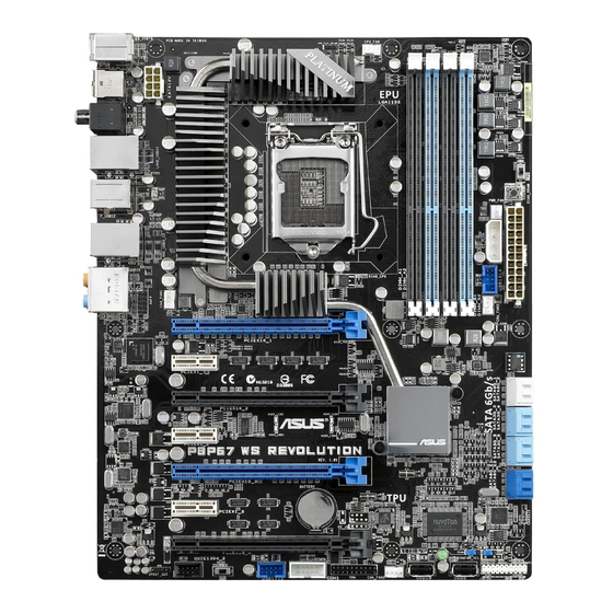
Page 28: Motherboard Overview
Motherboard overview 2.2.1 Motherboard layout Refer to 2.8 Connectors for more information about rear panel connectors and internal connectors. Chapter 2: Hardware information... -
Page 29: Layout Contents
TPM connector (20-1 pin TPM) 2-24 Serial port connector (10-1 pin COM1) 2-23 EPU Switch 2-11 IEEE 1394a port connector (10-1 pin IE1394_2) 2-21 Digital audio connector (4-1 pin SPDIF_OUT) 2-21 Front panel audio connector (10-1 pin AAFP) 2-23 ASUS P8P67 WS Revolution... -
Page 30: Central Processing Unit (Cpu)
ASUS will shoulder the cost of repair only if the damage is shipment/transit-related. • Keep the cap after installing the motherboard. ASUS will process Return Merchandise Authorization (RMA) requests only if the motherboard comes with the cap on the LGA1155 socket. -
Page 31: System Memory
The motherboard comes with four Double Data Rate 3 (DDR3) Dual Inline Memory Modules (DIMM) slots. A DDR3 module is notched differently from a DDR or DDR2 module. DO NOT install a DDR or DDR2 memory module to the DDR3 slot. Recommended memory configurations ASUS P8P67 WS Revolution... -
Page 32: Memory Configurations
• According to Intel spec definition, DDR3-1600 is supported for one DIMM per channel only. ASUS exclusively provides two DDR3-1600 DIMM support for each memory channel. • According to Intel CPU spec, DIMM voltage below 1.65V is recommended to protect the CPU. - Page 33 P8P67 WS Revolution Motherboard Qualified Vendors Lists (QVL) DDR���6��M��� capability 3-1600MHz capability -1600MHz capability Vendor Part No. Size SS/DS Timing Voltage DIMM socket support 2DIMM 4DIMM CORSAIR CMX6GX3M3A1600C9(XMP) 6GB ( 3x 2GB ) 9-9-9-24 1.65 CORSAIR CMD8GX3M4A1600C8(XMP) 8GB(4 x 2GB) 8-8-8-24 1.65...
-
Page 34: Memory Configuration
G.SKILL F3-10666CL9D-8GBRL 8GB 9-9-9-24 ( 2x 4GB ) GEIL GG34GB1333C9DC GEIL GL1L128M88BA115FW 9-9-9-24 ( 2x 2GB ) GEIL GG34GB1333C9DC 4GB(2 GEIL GL1L128M88BA12N 9-9-9-24 x 2GB) Hynix HMT112U6TFR8A-H9 Hynix H5TC1G83TFR Hynix HMT325U6BFR8C-H9 Hynix H5TQ2G83BFR Hynix HMT125U6BFR8C-H9 Hynix H5TQ1G83BFRH9C Hynix HMT125U6TFR8A-H9 Hynix H5TC1G83TFR Hynix HMT351U6BFR8C-H9... -
Page 35: Expansion Slots
PCIe 2.0 x1_1 slot PCIe 2.0 x16_2 slot (x8 mode) PCIe 2.0 x1_2 slot PCIe 2.0 x16_3 slot (single at x16 or dual at x8/x8 mode) PCIe 2.0 x1_3 slot PCIe 2.0 x16_4 slot (x8 mode) ASUS P8P67 WS Revolution... -
Page 36: Standard Interrupt Assignments
Standard Interrupt assignments Priority Standard function System Timer Keyboard Controller Programmable Interrupt Communications Port (COM1)* IRQ Holder for PCI Steering* Reserved Reserved System CMOS/Real Time Clock IRQ Holder for PCI Steering* IRQ Holder for PCI Steering* IRQ Holder for PCI Steering* Reserved Numeric Data Processor Primary IDE Channel... -
Page 37: Onboard Switches
Turning this switch to Enable will automatically detect the current PC loadings and intelligently moderate the power consumption. For ensuring the system performance, turn the switch setting to Enable when the system is powered off. ASUS P8P67 WS Revolution 2-11... - Page 38 DRAM_LED lights continuously. Replace the DIMMs with ones recommended in the Memory QVL (Qualified Vendors Lists) in this user manual or on the ASUS website at www.asus.com. • If you turn off the computer and replace DIMMs during the tuning process, the system continues memory tuning after turning on the computer.
-
Page 39: Onboard Leds
You may disable the POST State LEDs in BIOS. Refer to section 3.7.2 Boot Setting Configuration for details. TPU LED The TPU LED lights when the TPU switch is turned to Enable. ASUS P8P67 WS Revolution 2-13... - Page 40 EPU LED The EPU LED lights when the EPU switch is turned to Enable. Standby power LED The motherboard comes with a standby power LED that lights up to indicate that the system is ON, in sleep mode, or in soft-off mode. This is a reminder that you should shut down the system and unplug the power cable before removing or plugging in any motherboard component.
-
Page 41: Jumper
• Due to the chipset behavior, AC power off is required to enable C.P.R. function. You must turn off and on the power supply or unplug and plug the power cord before rebooting the system. ASUS P8P67 WS Revolution 2-15... - Page 42 Chassis Fan control setting (3-pin CHAFAN_SEL) These jumpers allow you to switch for fan pin selection. The CHAFAN_SEL jumper is for the front fans and rear fans control. Set to pins 1–2 when using 3-pin fans or pins 2–3 when using 4-pin fans. •...
-
Page 43: Internal Connectors
You must install Windows XP Service Pack 3 or later versions before using ® Serial ATA hard disk drives. The Serial ATA RAID feature is available only if you are using Windows XP SP3 or later versions. ® ASUS P8P67 WS Revolution 2-17... - Page 44 Intel P67 Serial ATA 3.0 Gb/s connectors ® (7-pin SATA3G_3–6 [blue]) These connectors connect to Serial ATA 3.0 Gb/s hard disk drives and optical disc drives via Serial ATA 3.0 Gb/s signal cables. If you installed Serial ATA hard disk drives, you can create a RAID 0, 1, 5, and 10 configuration with the Intel Rapid Storage Technology through the ®...
- Page 45 • the manual bundled in the motherboard support DVD. • When using hot-plug and NCQ, set the Marvell Controller item in the BIOS to [AHCI Mode]. Refer to section �.5.6 Onboard Devices Configuration for details. ASUS P8P67 WS Revolution 2-19...
- Page 46 Never connect a 1394 cable to the USB connectors. Doing so will damage the motherboard! You can connect the front panel USB cable to the ASUS Q-Connector (USB, blue) first, and then install the Q-Connector (USB) to the USB connector onboard if your chassis supports front panel USB ports.
- Page 47 This connector is for an additional Sony/Philips Digital Interface (S/PDIF) port(s). Connect the S/PDIF Out module cable to this connector, then install the module to a slot opening at the back of the system chassis. The S/PDIF module is purchased separately. ASUS P8P67 WS Revolution 2-21...
- Page 48 CPU, chassis, and power fan connectors (4-pin CPU_FAN; 4-pin CHA_FAN1/2/3; 3-pin PWR_FAN) Connect the fan cables to the fan connectors on the motherboard, ensuring that the black wire of each cable matches the ground pin of the connector. Do not forget to connect the fan cables to the fan connectors. Insufficient air flow inside the system may damage the motherboard components.
- Page 49 This connector is for a serial (COM) port. Connect the serial port module cable to this connector, then install the module to a slot opening at the back of the system chassis. The COM module is purchased separately. ASUS P8P67 WS Revolution 2-23...
- Page 50 10. TPM connector (20-1 pin TPM) This connector supports a Trusted Platform Module (TPM) system, which can securely store keys, digital certificates, passwords, and data. A TPM system also helps enhance network security, protects digital identities, and ensures platform integrity. This connector can also serve for G.P. Diagnosis card installtion.
- Page 51 Leave BIOS and pass control detection and sizing to OS Early CPU initiation Wake up AP Detect PS2 mouse/keyboard Initiate VGA BIOS 9A-9D USB initiation Resume from S1 Detect IDE Resume from S3 Initiate option ROM Resume from S4 ASUS P8P67 WS Revolution 2-25...
-
Page 52: Atx Power Connectors
• If you are uncertain about the minimum power supply requirement for your system, refer to the Recommended Power Supply Wattage Calculator at http://support.asus.com/PowerSupplyCalculator/PSCalculator. aspx?SLanguage=en-us for details. • If you want to use two or more high-end PCI Express x16 cards, use a PSU with 1000W power or above to ensure the system stability. -
Page 53: System Panel Connector
BIOS settings. Pressing the power switch for more than four seconds while the system is ON turns the system OFF. • Reset button (2-pin RESET) This 2-pin connector is for the chassis-mounted reset button for system reboot without turning off the system power. ASUS P8P67 WS Revolution 2-27... -
Page 54: Building Your Computer System
Building your computer system 2.3.1 Additional tools and components to build a PC system 1 bag of screws Philips (cross) screwdriver PC chassis Power supply unit Intel LGA 1155 CPU Intel LGA 1155 compatible CPU Fan DIMM SATA hard disk drive SATA optical disc drive (optional) Graphics card (optional) The tools and components in the table above are not included in the... -
Page 55: Cpu Installation
2.3.2 CPU installation ASUS P8P67 WS Revolution 2-29... - Page 56 2-30 Chapter 2: Hardware information...
-
Page 57: Cpu Heatsink And Fan Assembly Installation
2.3.3 CPU heatsink and fan assembly installation Apply the Thermal Interface Material to the CPU heatsink and CPU before you install the heatsink and fan if necessary. To install the CPU heatsink and fan assembly ASUS P8P67 WS Revolution 2-31... - Page 58 To uninstall the CPU heatsink and fan assembly 2-32 Chapter 2: Hardware information...
-
Page 59: Dimm Installation
2.3.4 DIMM installation To remove a DIMM ASUS P8P67 WS Revolution 2-33... -
Page 60: Motherboard Installation
2.3.5 Motherboard installation The diagrams in this section are for reference only. The motherboard layout may vary with models, but the installation steps remain the same. 2-34 Chapter 2: Hardware information... - Page 61 DO NOT overtighten the screws! Doing so can damage the motherboard. ASUS P8P67 WS Revolution 2-35...
-
Page 62: Atx Power Connection
2.3.6 ATX Power connection 2-36 Chapter 2: Hardware information... -
Page 63: Sata Device Connection
2.3.7 SATA device connection ASUS P8P67 WS Revolution 2-37... -
Page 64: Front I/O Connector
2.3.8 Front I/O Connector To install ASUS Q-Connector To install USB Connector To install front panel audio connector AAFP The actual location may vary with motherboards. 2-38 Chapter 2: Hardware information... -
Page 65: Expension Card Installation
2.3.9 Expension Card installation To install PCIe x16 cards To install PCIe x1 cards To install PCI cards ASUS P8P67 WS Revolution 2-39... -
Page 66: Rear Panel Connection
2.3.10 Rear panel connection Rear panel connectors 1. PS/2 mouse and keyboard port 7. USB 2.0 ports 5 and 6 2. Coaxial S/PDIF Out port 8. Optical S/PDIF Out port 3. LAN (RJ-45) port 2* 9. USB 2.0 ports 3 and 4 4. -
Page 67: Audio I/O Connections
Orange – – Center/Subwoofer Center/Subwoofer Black – Rear Speaker Out Rear Speaker Out Rear Speaker Out Gray – – – Side Speaker Out 2.3.11 Audio I/O connections Audio I/O ports Connect to Headphone and Mic ASUS P8P67 WS Revolution 2-41... - Page 68 Connect to Stereo Speakers Connect to 2.1 channel Speakers Connect to 4.1 channel Speakers 2-42 Chapter 2: Hardware information...
- Page 69 Connect to 5.1 channel Speakers Connect to 7.1 channel Speakers ASUS P8P67 WS Revolution 2-43...
-
Page 70: Starting Up For The First Time
Starting up for the first time After making all the connections, replace the system case cover. Be sure that all switches are off. Connect the power cord to the power connector at the back of the system chassis. Connect the power cord to a power outlet that is equipped with a surge protector. -
Page 71: Turning Off The Computer
BIOS setting. Pressing the power switch for more than four seconds lets the system enter the soft-off mode regardless of the BIOS setting. Refer to section 3.7 Power Menu for details. ASUS P8P67 WS Revolution 2-45... - Page 72 2-46 Chapter 2: Hardware information...
-
Page 73: Chapter 3: Bios Setup
This chapter tells how to change the system settings through the BIOS Setup menus. Detailed descriptions of the BIOS parameters are also provided. BIOS setup... - Page 74 BIOS setup program ..............3-7 Main menu .................. 3-10 Ai Tweaker menu Ai Tweaker menu menu ................ 3-15 Advanced menu ................. 3-22 Power menu ................3-29 Boot menu .................. 3-34 Tools menu ................. 3-38 Exit menu ..................3-42 ASUS P8P67 WS Revolution...
-
Page 75: Knowing Bios
USB mouse. The BIOS setup program can be used under two modes: EZ Mode and Advanced Mode. You can change modes from the Exit menu or from the Exit/Advanced Mode button in the EZ Mode/Advanced Mode screen. ASUS P8P67 WS Revolution... -
Page 76: Ez Mode
CPU/chassis/power fan speed the system, or enters the Advanced Mode EFI BIOS Utility - EZ Mode Exit/Advanced Mode P8P67 WS REVOLUTION English BIOS Version : 0602 Build Date : 11/04/2010 CPU Type : Intel(R) Core(TM) i5-2300 CPU 0 @ 2.80GHz... -
Page 77: Advanced Mode
The Advanced Mode provides advanced options for experienced end-users to configure the BIOS settings. The figure below shows an example of the Advanced Mode. Refer to the following sections for the detailed configurations. To access the EZ Mode, click Exit, then select ASUS EZ Mode. Menu Configuration... -
Page 78: Menu Items
Menu items The highlighted item on the menu bar displays the specific items for that menu. For example, selecting Main shows the Main menu items. The other items (Ai Tweaker, Advanced, Monitor, Boot, Tool, and Exit) on the menu bar have their respective menu items. Back button This button appears when entering a submenu. -
Page 79: Main Menu
Clock (RTC) RAM to clear the BIOS password. See section 2.2.7 Jumper for information on how to erase the RTC RAM. The Administrator or User Password items on top of the screen show • the default Not Installed. After you set a password, these items show Installed. ASUS P8P67 WS Revolution... -
Page 80: Administrator Password
Administrator Password If you have set an administrator password, we recommend that you enter the administrator password for accessing the system. Otherwise, you might be able to see or change only selected fields in the BIOS setup program. To set an administrator password: Select the Administrator Password item and press <Enter>. -
Page 81: User Password
To clear the user password, follow the same steps as in changing a user password, but press <Enter> when prompted to create/confirm the password. After you clear the password, the User Password item on top of the screen shows Not Installed. ASUS P8P67 WS Revolution... -
Page 82: Ai Tweaker Menu
Ai Tweaker menu The Ai Tweaker menu items allow you to configure overclocking-related items. Be cautious when changing the settings of the Ai Tweaker menu items. Incorrect field values can cause the system to malfunction. The configuration options for this section vary depending on the CPU and DIMM model you installed on the motherboard. - Page 83 Allows you to set the memory operating frequency. The configuration options vary with the BCLK/PEG Frequency item settings. Selecting a very high memory frequency may cause the system to become unstable! If this happens, revert to the default setting. ASUS P8P67 WS Revolution...
-
Page 84: Dram Timing Control
EPU Power Saving Mode [Disabled] Allows you to enable or disable the EPU power saving function. Configuration options: [Disabled] [Enabled] EPU Setting [AUTO] This item appears only when you set the EPU Power Saving Mode item to [Enabled.] and allows you to select the EPU power saving mode. Configuration options: [AUTO] [Light Power Saving Mode] [Medium Power Saving Mode] [Max Power Saving Mode] OC Tuner... - Page 85 This item appears only when you set the VRM Frequency item to [Manual] and allows you to set a fixed VRM frequency. Use the <+> and <-> keys to adjust the value. The values range from 300KHz to 500KHz with a 10KHz interval. ASUS P8P67 WS Revolution 3-11...
- Page 86 Reducing phase number under light system loading to increase VRM efficiency [Standard] Proceeds phase control depending on the CPU loading. [Optimized] Loads the ASUS optimized phase tuning profile. [Extreme] Proceeds the full phase mode. [Manual Adjustment] Allows manual adjustment. Manual Adjustment [Medium] This item appears only when you set the Phase Control item to [Manual Adjustment].
- Page 87 Voltage, VCCSA Voltage, VCCIO Voltage, CPU PLL Voltage, and PCH Voltage items are labelled in different color, indicating the risk levels of high voltage settings. • The system may need better cooling system to work stably under high voltage settings. ASUS P8P67 WS Revolution 3-13...
- Page 88 DRAM DATA REF Voltage on CHA/B [Auto] Allows you to set the DRAM DATA Reference Voltage on Channel A/B. The values range from 0.395x to 0.630x with a 0.005x interval. Different ratio might enhance DRAM overclocking ability. DRAM CTRL REF Voltage on CHA/B [Auto] Allows you to set the DRAM Control Reference Voltage on Channel A/B.
-
Page 89: Advanced Menu
Trusted Computing > TPM Configuration Enables or Disables TPM support. TPM SUPPORT Disabled O.S. will not show TPM. Reset of platform is required. This item appears only when you install TPM module to the motherboard. ASUS P8P67 WS Revolution 3-15... -
Page 90: Cpu Configuration
�.5.2 CPU Configuration The items in this menu show the CPU-related information that the BIOS automatically detects. The items shown in this screen may be different due to the CPU you installed. EFI BIOS Utility - Advanced Mode Exit Ai Tweaker Main Advanced Monitor... - Page 91 Enhanced Halt State. CPU C3 Report [Enabled] Allows you to disable or enable the CPU C3 report to OS. CPU C6 Report [Enabled] Allows you to disable or enable the CPU C6 report to OS. ASUS P8P67 WS Revolution 3-17...
-
Page 92: Pch Configuration
S.M.A.R.T. Status Check Enabled SATA6G_1 (Gray) Not Present Hot Plug Disabled SATA6G_2 (Gray) Not Present Hot Plug Disabled SATA3G_3 (Blue) ASUS CB-521 ATAPI Hot Plug Disabled SATA3G_4 (Blue) Not Present Hot Plug Disabled SATA3G_5 (Blue) Not Present Hot Plug Disabled... - Page 93 When read/write of your hard disk errors occur, this feature allows the hard disk to report warning messages during the POST. Configuration options: [Enabled] [Disabled] Hot Plug [Enabled] Allows you to enable or disable the hot plug support of the SATA ports. Configuration options: [Disabled] [Enabled] ASUS P8P67 WS Revolution 3-19...
-
Page 94: Usb Configuration
�.5.5 USB Configuration The items in this menu allow you to change the USB-related features. EFI BIOS Utility - Advanced Mode Exit Main Ai Tweaker Advanced Monitor Boot Tool Back Advanced\ USB Configuration > USB Configuration Enables Legacy USB support. AUTO option disables legacy support if no USB Devices: USB devices are connected. -
Page 95: Onboard Devices Configuration
[HD] Sets the front panel audio connector (AAFP) mode to high definition audio. [AC97] Sets the front panel audio connector (AAFP) mode to legacy AC’97. ASUS P8P67 WS Revolution 3-21... - Page 96 SPDIF Out Type [SPDIF] [SPDIF] Sets to [SPDIF] for SPDIF audio output. [HDMI] Sets to [HDMI] for HDMI audio output. Renesas USB 3.0 Controller [Enabled] [Enabled] Enables the USB 3.0 controller. [Disabled] Disables the controller. VIA 1394 Controller [Enabled] [Enabled] Enables the onboard IEEE 1394a controller.
-
Page 97: Apm
Sets the Ctrl+Esc key on the PS/2 keyboard to turn on the system. [Power Key] Sets Power key on the PS/2 keyboard to turn on the system. This feature requires an ATX power supply that provides at least 1A on the +5VSB lead. ASUS P8P67 WS Revolution 3-23... - Page 98 Power On By PS/2 Mouse [Disabled] [Disabled] Disables the Power On by a PS/2 mouse. [Enabled] Enables the Power On by a PS/2 mouse. This feature requires an ATX power supply that provides at least 1A on the +5VSB lead. Power On By Lan1(82579) Device [Disabled] [Disabled] Disables the PME to wake up from S5 by PCI devices.
-
Page 99: Monitor Menu
(RPM). If the fan is not fan speed in rotations per minute (RPM). If the fan is not connected to the motherboard, the field shows N/A. Select Ignore if you do not wish to display the detected speed. ASUS P8P67 WS Revolution 3-25... - Page 100 CPU Q-Fan Control [Enabled] [Disabled] Disables the CPU Q-Fan control feature. [Enabled] Enables the CPU Q-Fan control feature. CPU Fan Speed Low Limit [600 RPM] This item appears only when you enable the CPU Q-Fan Control feature and allows you to disable or set the CPU fan warning speed. Configuration options: [Ignore] [200 RPM] [300 RPM] [400 RPM] [500 RPM] [600 RPM] CPU Fan Profile [Standard]...
- Page 101 Select Ignore if you do not want to detect this item. Anti Surge Support [Enabled] This item allows you to enable or disable the Anti Surge function. Configuration options: [Disabled] [Enabled] ASUS P8P67 WS Revolution 3-27...
-
Page 102: Boot Menu
Enables the full screen logo display feature. [Disabled] Disables the full screen logo display feature. Set this item to [Enabled] to use the ASUS MyLogo 2™ feature. Option ROM Messages [Force BIOS] [Force BIOS] The third-party ROM messages will be forced to display during the boot sequence. -
Page 103: Tool Menu
> ASUS Drive Xpert 3.8.1 ASUS EZ Flash Utility Allows you to run ASUS EZ Flash Utility. When you press <Enter> to start the application. For more details, refer to section 3.10.2 ASUS EZ Flash Utility. ASUS P8P67 WS Revolution... -
Page 104: Asus O.c. Profile
Exit Main Ai Tweaker Advanced Monitor Boot Tool Back Tool\ ASUS O.C. Profile > O.C. Profile Configuration Save BIOS settings to Profile ========================================================== Setup Profile1 Status : Not Installed Setup Profile2 Status : Not Installed Setup Profile3 Status : Not Installed... -
Page 105: Asus Drive Xpert
Drive Xpert Device(s) List: SATA 6G E1 (Navy Blue) / SATA 6G E2 (Navy Blue) Press <Enter> to display the information of the hard disks which are connected to the SATA6G_E1 and SATA6G_E2 connectors on the motherboard. ASUS P8P67 WS Revolution 3-31... -
Page 106: Exit Menu
Exit Load Optimized Defaults Save Changes & Reset Discard Changes & Exit ASUS EZ Mode Launch EFI Shell from filesystem device Load Optimized Defaults This option allows you to load the default values for each of the parameters on the Setup menus. -
Page 107: 3.10 Updating Bios
Carefully follow the instructions of this chapter to update your BIOS if necessary. Visit the ASUS website (www.asus.com) to download the latest BIOS file for this motherboard. The following utilities allow you to manage and update the motherboard BIOS setup program. -
Page 108: Asus Update Utility
3.10.1 ASUS Update utility The ASUS Update is a utility that allows you to manage, save, and update the motherboard BIOS in Windows environment. The ASUS Update utility allows you ® • Update the BIOS directly from the Internet •... - Page 109 Select the ASUS FTP site nearest you to avoid network traffic. If you want to enable the BIOS downgradable function and auto BIOS backup function, check the checkboxs before the two items on the screen. Select the BIOS version that you want to download.
- Page 110 The screenshots in this section are for reference only. The actual BIOS information vary by models. • Refer to the software manual in the support DVD or visit the ASUS website at www.asus.com for detailed software configuration. 3-36 Chapter 3: BIOS setup...
-
Page 111: Asus Ez Flash Utility
3.10.2 ASUS EZ Flash Utility The ASUS EZ Flash Utility feature allows you to update the BIOS without having to use a bootable floppy disk or an OS-based utility. Before you start using this utility, download the latest BIOS from the ASUS website at www.asus.com. -
Page 112: Asus Crashfree Bios 3 Utility
3.10.3 ASUS CrashFree BIOS 3 utility The ASUS CrashFree BIOS 3 utility is an auto recovery tool that allows you to restore the BIOS file when it fails or gets corrupted during the updating process. You can restore a corrupted BIOS file using the motherboard support DVD or a USB flash drive that contains the BIOS file. -
Page 113: Asus Bios Updater
3.10.4 ASUS BIOS Updater The ASUS BIOS Updater allows you to update BIOS in DOS environment. This utility also allows you to copy the current BIOS file that you can use as a backup when the BIOS fails or gets corrupted during the updating process. -
Page 114: Backing Up The Current Bios
Backing up the current BIOS To backup the current BIOS file using the BIOS Updater Ensure that the USB flash drive is not write-protected and has enough free space to save the file. At the FreeDOS prompt, type bupdater /o[filename] and press <Enter>. D:\>bupdater /oOLDBIOS1.rom Filename Extension The [filename] is any user-assigned filename with no more than eight... -
Page 115: Updating The Bios File
Select the Load Optimized Defaults item under the Exit BIOS menu. See Chaper 3 of your motherboard user manual for details. • Ensure to connect all SATA hard disk drives after updating the BIOS file if you have disconnected them. ASUS P8P67 WS Revolution 3-41... - Page 116 3-42 Chapter 3: BIOS setup...
-
Page 117: Chapter 4: Software Support
This chapter describes the contents of the support DVD that comes with the motherboard package and the software. Software support... - Page 118 Chapter summary Installing an operating system ........... 4-1 Support DVD information ............4-1 Software information ..............4-3 RAID configurations ..............4-16 Creating a RAID driver disk ............4-25 ASUS P8P67 WS Revolution...
-
Page 119: Installing An Operating System
The contents of the support DVD are subject to change at any time without notice. Visit the ASUS website at www.asus.com for updates. 4.2.1 Running the support DVD Place the support DVD into the optical drive. -
Page 120: Obtaining The Software Manuals
Acrobat Reader from the Utilities menu before opening the files. ® ® Click the Manual tab. Click ASUS Motherboard Utility Guide from the manual list on the left. The Manual folder of the support DVD appears. Double- click the folder of your selected software. -
Page 121: Software Information
4.3.1 AI Suite II AI Suite II is an all-in-one interface that integrates several ASUS utilities and allows users to launch and operate these utilities simultaneously. Installing AI Suite II To install AI Suite II on your computer Place the support DVD to the optical drive. -
Page 122: Digi+ Vrm
4.3.2 DIGI+ VRM ASUS DIGI+ VRM allows you to adjust VRM voltage and frequency modulation to enhance reliability and stability. It also provides the highest power efficiency, generating less heat to longer component lifespan and minimize power loss. After installing AI Suite II from the motherboard support DVD, launch DIGI+ VRM by clicking Tool >... - Page 123 The actual performance boost may vary depending on your CPU specification. • Do not remove the thermal module. The thermal conditions should be monitored. Refer to the software manual in the support DVD or visit the ASUS website at www.asus.com for detailed software configuration. ASUS P8P67 WS Revolution...
-
Page 124: Turbov Evo
II from the motherboard support DVD, launch TurboV EVO by clicking Tool > TurboV EVO on the AI Suite II main menu bar. Refer to the software manual in the support DVD or visit the ASUS website at www.asus.com for detailed software configuration. - Page 125 You will requested to restart the system. Click Yes to make the change take effect. CPU Ratio Click to activate the CPU Ratio Applies all changes Click to restore immediately all start-up Undoes all changes settings without applying ASUS P8P67 WS Revolution...
-
Page 126: Auto Tuning
The CPU Ratio bars show the status of the CPU cores, which vary with your CPU model. Auto Tuning ASUS TurboV EVO includes two auto tuning modes, providing the most flexible auto-tuning options. • The overclocking result varies with the CPU model and the system configuration. - Page 127 Read through the warning messages and click OK to start auto-overclocking. TurboV automatically overclocks the CPU and memory and restarts the system. After re-entering Windows, a message appears indicating the current overclocking result. To keep the result, click Stop. ASUS P8P67 WS Revolution...
- Page 128 If you did not click Stop in the previous step, TurboV automatically starts further system overclocking and stability test. An animation appears indicating the overclocking process. Click Stop if you want to cancel the Overclocking process. TurboV automatically adjusts and saves BIOS settings and restarts the system.
-
Page 129: Epu
Select From the Last Reset to show the total CO2 that has been reduced *• since you click the Clear button • Refer to the software manual in the support DVD or visit the ASUS website at www.asus.com for detailed software configuration. ASUS P8P67 WS Revolution 4-11... -
Page 130: Fan Xpert
70°C. User: Allows you to configure the CPU fan profile under certain limitations. • Refer to the software manual in the support DVD or visit the ASUS website at www.asus.com for detailed software configuration. 4-12 Chapter 4: Software support... -
Page 131: Probe Ii
Loads Applies your Loads the your saved changes default threshold configuration values for each sensor Refer to the software manual in the support DVD or visit the ASUS website at www.asus.com for detailed software configuration. ASUS P8P67 WS Revolution 4-13... -
Page 132: Audio Configurations
4.�.7 Audio configurations The Realtek audio CODEC provides 8-channel audio capability to deliver the ® ultimate audio experience on your computer. The software provides Jack-Detection function, S/PDIF Out support, and interrupt capability. The CODEC also includes the Realtek proprietary UAJ (Universal Audio Jack) technology for all audio ports, ®... - Page 133 Realtek HD Audio Manager for Windows XP Exit Configuration button options Minimize Control settings button window Information button Refer to the software manual in the support DVD or visit the ASUS website at www.asus.com for detailed software configuration. ASUS P8P67 WS Revolution 4-15...
-
Page 134: Raid Configurations
RAID configurations The motherboard supports the following SATA RAID solutions: Intel Rapid Storage Technology with RAID 0, RAID 1, RAID 10 and RAID ® • 5 support. Mavell RAID utility with RAID 0 and RAID 1 support. ® • • You must install Windows XP Service Pack 3 or later versions before using ®... -
Page 135: Installing Serial Ata Hard Disks
Turn on the system. During POST, press <Ctrl> + <I> to display the utility main menu. Intel(R) Rapid Storage Technology - Option ROM - v10.0.0.1032 Copyright(C) 2003-10 Intel Corporation. All Rights Reserved. [ MAIN MENU ] 1. Create RAID Volume 3. Reset Disks to Non-RAID 2. Delete RAID Volume 4. Recovery Volume Options 5. Exit [ DISK/VOLUME INFORMATION ] RAID Volumes: None defined. Physical Devices: Port Device Model Serial # Size Type/Status(Vol ID) 0 ST3160812AS 9LS0HJA4 149.0GB Non-RAID Disk 1 ST3160812AS 9LS0F4HL 149.0GB Non-RAID Disk 2 ST3160812AS 3LS0JYL8 149.0GB Non-RAID Disk 3 ST3160812AS 9LS0BJ5H 149.0GB Non-RAID Disk [↑↓]-Select [ESC]-Exit [ENTER]-Select Menu ASUS P8P67 WS Revolution 4-17... -
Page 136: Creating A Raid Set
The navigation keys at the bottom of the screen allow you to move through the menus and select the menu options. The RAID BIOS setup screens shown in this section are for reference only and may not exactly match the items on your screen. The utility supports maximum four hard disk drives for RAID configuration. - Page 137 When the Create Volume item is selected, press <Enter>. The following warning message appears: WARNING: ALL DATA ON SELECTED DISKS WILL BE LOST. Are you sure you want to create this volume? (Y/N): Press <Y> to create the RAID volume and return to the main menu, or <N> to go back to the CREATE VOLUME menu. ASUS P8P67 WS Revolution 4-19...
-
Page 138: Deleting A Raid Set
Deleting a RAID set Take caution when deleting a RAID set. You will lose all data on the hard disk drives when you delete a RAID set. To delete a RAID set: From the utility main menu, select 2. Delete RAID Volume and press <Enter>. -
Page 139: Marvell Raid Utility
Press <Space> to select the hard drives to be included in the RAID array. An asterisk (*) appears in front of the selected hard drive. After selecting all the drives needed for the RAID array, press <Enter> to continue. ASUS P8P67 WS Revolution 4-21... - Page 140 Marvell BIOS Setup (c) 2009 Marvell Technology Group Ltd. Configure->Select free disksCreate Virtual Disk HBA 0: Marvell 0 RAID Level : RAID 0 ├ Virtual Disks Max Size(MB) : 305253 └ Free Physical Disks Stripe Size : 64KB * ├ PD 0: ST3160812AS Gigabyte Rounding : 1G * └ PD 8: ST3160812AS Quick Init : Yes Name : Default Threshold(%) : 90 Next ▶ ▶ Help Virtual disk configurations. ENTER: Select F10: Exit/Save ESC: Return Use the up or down arrow key to move the selection bar and press <Enter> to configure further RAID settings.
-
Page 141: Delete An Existing Raid Array
Select the RAID array to delete and press <Enter>. Select Delete and press <Enter>. Marvell BIOS Setup (c) 2009 Marvell Technology Group Ltd. Topology Information HBA 0: Marvell 0 ID : 0 ├ Virtual Disks Name : New_VD │ └ VD 0: New_VD Status : Functional │ ├ PD 0: ST3160812AS [Delete] Stripte Size : 64K │ └ PD 8: ST3160812AS RAID Mode : RAID0 Size : 304128MB └ Free Physical Disks BGA Status : N/A Number of PDs : 2 Members : 0 8 ▶ ▶ Help Delete the selected virtual disk. ENTER: Operation F10: Exit/Save ESC: Return ASUS P8P67 WS Revolution 4-23... - Page 142 The following warning message appears: Delete Virtual Disk Do you want to delete this virtual disk ? Yes No Press <Y> to delete the selected RAID array. The following warning message appears: Delete MBR Do you want to delete MBR from this virtual disk ? Yes No Press <Y> to delete the Master Boot Record (MBR) from the selected RAID array. Press <F10>. The following warning message appears: Exit Do you want to exit from Marvell BIOS Setup? Yes No...
-
Page 143: Creating A Raid Driver Disk
Go to the Make Disk menu, and then click Intel AHCI/RAID Driver Disk to create a RAID driver disk. Select USB floppy disk drive as the destination disk. Follow the succeeding screen instructions to complete the process. Write-protect the floppy disk to avoid a computer virus infection. ASUS P8P67 WS Revolution 4-25... -
Page 144: Installing The Raid Driver During Windows ® Os Installation
4.5.3 Installing the RAID driver during Windows ® installation To install the RAID driver in Windows ® During the OS installation, the system prompts you to press the F6 key to install third-party SCSI or RAID driver. Press <F6>, and then insert the floppy disk with RAID driver into the USB floppy disk drive. -
Page 145: Using A Usb Floppy Disk Drive
(VID) and Product ID (PID) are displayed. Browse the contents of the RAID driver disk to locate the file txtsetup.oem. Double-click the file. A window appears, allowing you to select the program for opening the oem file. ASUS P8P67 WS Revolution 4-27... - Page 146 Use Notepad to open the file. Find the [HardwareIds.scsi.iaAHCI_DesktopWorkstationServer] and [HardwareIds.scsi.iaStor_DesktopWorkstationServer] sections in the txtsetup.oem file. Type the following line to the bottom of the two sections: id = “USB\VID_xxxx&PID_xxxx”, “usbstor” [HardwareIds.scsi.iaAHCI_DesktopWorkstationServer] id= “PCI\VEN_8086&DEV_1C02&CC_0106”,”iaStor” id= “USB\VID_03EE&PID_6901”, “usbstor” [HardwareIds.scsi.iaStor_DesktopWorkstationServer] id= “PCI\VEN_8086&DEV_2822&CC_0104”,”iaStor” id= “USB\VID_03EE&PID_6901”, “usbstor” Add the same line to both sections. The VID and PID vary with different vendors.
-
Page 147: Chapter 5: Multiple Gpu Technology Support
This chapter describes how to install and configure multiple ATI CrossFireX™ and ® NVIDIA SLI™ graphics cards. ® Multiple GPU technology support... -
Page 148: Chapter Summary
Chapter summary CrossFireX™ technology ............ 5-1 ® NVIDIA SLI™ technology ............5-5 ® NVIDIA CUDA™ technology ............ 5-11 ® ASUS P8P67 WS Revolution... -
Page 149: Ati ® Crossfirex™ Technology
For Windows XP, go to Control Panel > Add/Remove Programs. For Windows Vista, go to Control Panel > Programs and Features. Select your current graphics card driver/s. For Windows XP, select Add/Remove. For Windows Vista, select Uninstall. Turn off your computer. ASUS P8P67 WS Revolution... -
Page 150: Installing Crossfirex Graphics Cards
5.1.3 Installing CrossFireX graphics cards The following pictures are for reference only. The graphics cards and the motherboard layout may vary with models, but the installation steps remain the same. Prepare two CrossFireX-ready graphics cards. Insert the two graphics card into the PCIEX16 slots. -
Page 151: Installing The Device Drivers
Windows notification area and select Cayalist Control Center. The Catalyst Control Center Setup Assistant appears when the system detects the existance of multi- graphics cards. Click Go to continue to the Catalyst Control Center Advanced View window. ASUS P8P67 WS Revolution... - Page 152 Enabling Dual CrossFireX settings In the Catalyst Control Center window, click Graphics Settings > CrossFireX > Configure. From the Graphics Adapter list, select the graphics card to act as the display GPU. Select Enable CrossFireX. Click Apply, and then click OK to exit the window.
-
Page 153: Nvidia ® Sli™ Technology
We recommend that you install additional chassis fans for better thermal environment. • The NVIDIA Triple SLI technology is supported by Windows Vista™ ® operating system only. • Visit the NVIDIA zone website at http://www.nzone.com for the latest certified graphics card and supported 3D application list. ASUS P8P67 WS Revolution... -
Page 154: Installing Two Sli-Ready Graphics Cards
5.2.2 Installing two SLI-ready graphics cards The following pictures are for reference only. The graphics cards and the motherboard layout may vary with models, but the installation steps remain the same. Prepare two SLI-ready graphics cards. Insert the two graphics card into the PCIEX16 slots. -
Page 155: Installing Three Sli-Ready Graphics Cards
Connect three independent auxiliary power sources from the power supply to the three graphics cards separately. Connect a VGA or a DVI cable to the graphics card. 3-Way SLI bridge ASUS P8P67 WS Revolution... -
Page 156: Installing The Device Drivers
5.2.4 Installing the device drivers Refer to the documentation that came with your graphics card package to install the device drivers. • Ensure that your PCI Express graphics card driver supports the ® NVIDIA SLI™ technology. Download the latest driver from the NVIDIA website at www.nvidia.com. - Page 157 B2. From the Personalization window, select Display Settings. B3. From the Display Settings dialog box, click Advanced Settings. B4. Select the NVIDIA GeForce tab, and then click Start the NVIDIA Control Panel. ASUS P8P67 WS Revolution...
- Page 158 B5. The NVIDIA Control Panel window appears. Enabling Dual SLI settings From the NVIDIA Control Panel window, select Set SLI Configuration. Click Enable SLI and set the display for viewing SLI rendered content. When done, click Apply. Enabling Triple SLI settings From the NVIDIA Control Panel window, select Set SLI Configuration, and then click Enable 3-way NVIDIA...
-
Page 159: Nvidia ® Cuda™ Technology
Prepare one NVIDIA Quadro graphics card and up to three NVIDIA Tesla computing processor cards. Insert the Quadro graphics card into the PCIe x16_1 slot. Ensure that the card is properly seated on the slot. ASUS P8P67 WS Revolution 5-11... - Page 160 Insert the Tesla computing processor card(s) into the PCIe x16_2, PCIe x16_3 or PCIe x16_4 slot. Ensure that the cards are properly seated on the slot. Connect either one 8-pin power connector or two 6-pin power connectors from the power supply to the Quadro graphics card and Tesla computing processor card(s).
Need help?
Do you have a question about the P8P67 WS REVOLUTION and is the answer not in the manual?
Questions and answers