Asus P8P67 LX User Manual
User manual
Hide thumbs
Also See for P8P67 LX:
- User manual (134 pages) ,
- User manual (136 pages) ,
- Quick start manual (12 pages)
Table of Contents
Advertisement
Quick Links
Advertisement
Table of Contents

Subscribe to Our Youtube Channel
Related Manuals for Asus P8P67 LX


Summary of Contents for Asus P8P67 LX
- Page 1 P8P67 LX...
- Page 2 Product warranty or service will not be extended if: (1) the product is repaired, modified or altered, unless such repair, modification of alteration is authorized in writing by ASUS; or (2) the serial number of the product is defaced or missing.
-
Page 3: Table Of Contents
Contents Notices ......................vi Safety information ..................vii About this guide ..................vii P8P67 LX specifications summary ............ix Chapter 1 Product introduction Welcome! ..................1-1 Package contents ................. 1-1 Special features ................1-1 1.3.1 Product highlights ............1-1 1.3.2 Innovative ASUS features .......... - Page 4 Managing and updating your BIOS ..........2-1 2.1.1 ASUS Update utility ............2-1 2.1.2 ASUS EZ Flash 2 ............2-2 2.1.3 ASUS CrashFree BIOS 3 utility ........2-3 2.1.4 ASUS BIOS Updater ............2-4 BIOS setup program ..............2-7 Main menu .................. 2-11 2.3.1 System Language [English] ...........2-11...
- Page 5 Option ROM Messages [Force BIOS] ......2-26 2.7.4 Setup Mode [EZ Mode] ..........2-26 Tools menu ................. 2-27 2.8.1 ASUS EZ Flash 2 ............2-27 2.8.2 ASUS SPD Information ..........2-27 2.8.3 ASUS O.C. Profile ............2-27 Exit menu ..................2-28...
-
Page 6: Notices
Complying with the REACH (Registration, Evaluation, Authorisation, and Restriction of Chemicals) regulatory framework, we published the chemical substances in our products at ASUS REACH website at http://csr.asus.com/english/REACH.htm. DO NOT throw the motherboard in municipal waste. This product has been designed to enable proper reuse of parts and recycling. -
Page 7: Safety Information
Safety information Electrical safety • To prevent electric shock hazard, disconnect the power cable from the electric outlet before relocating the system. • When adding or removing devices to or from the system, ensure that the power cables for the devices are unplugged before the signal cables are connected. If possible, disconnect all power cables from the existing system before you add a device. -
Page 8: Conventions Used In This Guide
Refer to the following sources for additional information and for product and software updates. ASUS websites The ASUS website provides updated information on ASUS hardware and software products. Refer to the ASUS contact information. Optional documentation Your product package may include optional documentation, such as warranty flyers, that may have been added by your dealer. -
Page 9: P8P67 Lx Specifications Summary
Extreme Memory Profile (XMP) ® The maximum 32GB memory capacity can be supported with 8GB or above DIMMs. ASUS will update the memory QVL once the DIMMs are available in the market. ** Hyper DIMM support is subject to the physical characteristics of individual CPUs. - Page 10 Auto Tuning ASUS Hybrid Switches - MemOK! - Turbo Key II ASUS Quiet Thermal Solutions - ASUS Fanless Design: Stylish Heatsink Solution - ASUS Fan Xpert ASUS EZ DIY - UEFI BIOS - ASUS AI Suite II - ASUS CrashFree BIOS 3 - ASUS EZ Flash 2 - ASUS MyLogo 2™...
- Page 11 P8P67 LX specifications summary Other features 100% All High-quality Conductive Polymer Capacitors Rear panel ports 1 x PS/2 Mouse port (green) 1 x PS/2 Keyboard port (purple) 1 x Optical S/PDIF output 1 x LAN (RJ-45) port 6 x USB 2.0/1.1 ports 2 x USB 3.0 ports (blue)
-
Page 12: Chapter 1 Product Introduction
® The motherboard delivers a host of new features and latest technologies, making it another standout in the long line of ASUS quality motherboards! Before you start installing the motherboard, and hardware devices on it, check the items in your package with the list below. - Page 13 This motherboard provides convenient connectivity to external home theater audio systems via the optical S/PDIF (SONY-PHILIPS Digital Interface) out connecor at the back I/O. The S/PDIF transfers digital audio without converting it to analog format and keeps the best signal quality. ASUS P8P67 LX...
-
Page 14: Innovative Asus Features
Innovative ASUS features ASUS UEFI BIOS (EZ Mode) The new ASUS UEFI BIOS is an Unified Extensible Firmware Interface that offers a user-friendly interface that goes beyond traditional keyboard- only BIOS control to enable more flexible and convenient mouse input. -
Page 15: Asus Turbov
ASUS TurboV Feel the adrenaline rush of real-time OC-now a reality with the ASUS TurboV. This easy OC tool allows you to overclock without exiting or rebooting the OS; and its user-friendly interface makes overclock with just a few clicks away. Moreover, the ASUS OC profiles in TurboV provides the best O.C. - Page 16 BIOS file using the bundled support DVD or USB flash disk that contains the latest BIOS file. ASUS EZ Flash 2 ASUS EZ Flash 2 is a utility that allows you to update the BIOS without using an OS-based utility. C.P.R. (CPU Parameter Recall) The BIOS C.P.R.
-
Page 17: Before You Proceed
• Before you install or remove any component, ensure that the ATX power supply is switched off or the power cord is detached from the power supply. Failure to do so may cause severe damage to the motherboard, peripherals, or components. ASUS P8P67 LX... -
Page 18: Motherboard Overview
Place six screws into the holes indicated by circles to secure the motherboard to the chassis. Do not overtighten the screws! Doing so can damage the motherboard. Place this side towards the rear of the chassis P8P67 LX Chapter 1: Product introduction... -
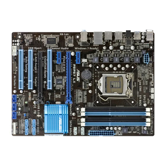
Page 19: Motherboard Layout
15. USB connectors (10-1 pin USB78, USB910, USB1112) 1-32 ® 7. DDR3 DIMM slots 1-14 16. Digital audio connector (4-1 pin SPDIF_OUT) 1-28 8. MemOK! switch 1-33 17. Serial port connector (10-1 pin COM1) 1-27 9. DRAM LED 1-34 ASUS P8P67 LX... -
Page 20: Central Processing Unit (Cpu)
Contact your retailer immediately if the PnP cap is missing, or if you see any damage to the PnP cap/socket contacts/motherboard components. ASUS will shoulder the cost of repair only if the damage is shipment/transit-related. • Keep the cap after installing the motherboard. ASUS will process Return Merchandise Authorization (RMA) requests only if the motherboard comes with the cap on the LGA1155 socket. - Page 21 CPU notches. The CPU fits in only one correct orientation. DO NOT force the CPU into the socket to prevent bending Gold the connectors on the socket and triangle damaging the CPU! mark Alignment keys ASUS P8P67 LX 1-10...
- Page 22 Apply some Thermal Interface Material to the exposed area of the CPU that the heatsink will be in contact with, ensuring that it is spread in an even thin layer. Some heatsinks come with pre- applied thermal paste. If so, skip this step.
-
Page 23: Installing The Cpu Heatsink And Fan
The type of CPU heatsink and fan assembly may differ, but the installation steps and functions should remain the same. The illustration above is for reference only. ASUS P8P67 LX 1-12... -
Page 24: Uninstalling The Cpu Heatsink And Fan
Connect the CPU fan cable to the connector on the motherboard labeled CPU_FAN. CPU_FAN P8P67 LX P8P67 LX CPU fan connector Do not forget to connect the CPU fan connector! Hardware monitoring errors can occur if you fail to plug this connector. -
Page 25: System Memory
The figure illustrates the location of the DDR3 DIMM sockets: Channel Sockets Channel A DIMM_A1 and DIMM_A2 P8P67 LX Channel B DIMM_B1 and DIMM_B2 P8P67 LX 240-pin DDR3 DIMM sockets ASUS P8P67 LX 1-14... -
Page 26: Memory Configurations
• The maximum 32GB memory capacity can be supported with 8GB or above DIMMs. ASUS will update the memory QVL once the DIMMs are available in the market. • The default memory operation frequency is dependent on its Serial Presence Detect (SPD), which is the standard way of accessing information from a memory module. - Page 27 P8P67 LX Motherboard Qualified Vendors Lists (QVL) DDR3-2133(O.C.) MHz capability DIMM socket support (Optional) Chip Chip Vendors Part No. Size Timing Voltage Brand GEIL GU34GB2133C9DC(XMP) 4GB(2 x 2GB) DS - 9-9-9-28 1.65V • KINGSTON KHX2133C9AD3T1K2/4GX(XMP) 4GB(2x 2GB) DS - 1.65V •...
- Page 28 DDR3-1600(O.C.) MHz capability DIMM socket Chip support (Optional) Vendors Part No. Size Chip NO. Timing Voltage Brand 1.65V- A-Data AD31600E001GM(O)U3K 3GB(3 x 1GB) SS - 8-8-8-24 • • • 1.85V A-Data AD31600X002GMU(XMP) 4GB(2 x 2GB) DS - 7-7-7-20 1.75-1.85V • •...
- Page 29 7-7-7-20 1.75V • • • OCZ3G1333LV6GK 6GB(3 x 2GB) DS 9-9-9-20 1.65V • • OCZ3P1333LV6GK 6GB(3 x 2GB) DS 7-7-7-20 1.65V • OCZ3X1333LV6GK(XMP) 6GB(3 x 2GB) DS 8-8-8-20 1.60V • • • (continued on the next page) ASUS P8P67 LX 1-18...
- Page 30 DDR3-1333 MHz capability DIMM socket Chip support (Optional) Vendors Part No. Size Chip NO. Timing Voltage Brand OCZ3G1333LV8GK 8GB(2x 4GB) 9-9-9-20 1.65V • • OCZ3RPR1333C9LV8GK 8GB(2x 4GB) 9-9-9-20 1.65V • • • AL7F8G73D-DG1 A3P1GF3DGF928M9B05 8-8-8-24 1.5V • • • AL8F8G73D-DG1 A3P1GF3DGF928M9B05 8-8-8-24 1.5V •...
- Page 31 • C*: Supports two pairs of modules inserted into both the blue slots and the black slots as two pairs of dual-channel memory configuration. Visit the ASUS website at www.asus.com for the latest QVL. ASUS P8P67 LX 1-20...
-
Page 32: Installing A Dimm
1.7.3 Installing a DIMM Unplug the power supply before adding or removing DIMMs or other system components. Failure to do so can cause severe damage to both the motherboard and the components. Press the retaining clips outward to DIMM notch unlock a DIMM socket. -
Page 33: Expansion Slots
PCI Express specifications. 1.8.5 PCI Express 2.0 x16 slots This motherboard has two PCI Express 2.0 x16 slots that support PCI Express 2.0 x16 graphic cards complying with the PCI Express specifications. ASUS P8P67 LX 1-22... - Page 34 PCI Express operating mode VGA configuration PCIe x16_1 PCIe x16_2 Single VGA/PCIe card x16 (Recommended for single VGA card) Dual VGA/PCIe card • In single VGA card mode, use the PCIe 2.0 x16_1 slot (blue) for a PCI Express x16 graphics card to get better performance.
-
Page 35: Jumpers
Normal Clear RTC (Default) P8P67 LX Clear RTC RAM To erase the RTC RAM: 1. Turn OFF the computer and unplug the power cord. 2. Move the jumper cap from pins 1-2 (default) to pins 2-3. Keep the cap on pins 2-3 for about 5-10 seconds, then move the cap back to pins 1-2. -
Page 36: Connectors
1.10 Connectors 1.10.1 Rear panel connectors PS/2 Mouse port (green). This port is for a PS/2 mouse. LAN (RJ-45) port. This port allows Gigabit connection to a Local Area Network (LAN) through a network hub. Refer to the table below for the LAN port LED indications. LAN port LED indications Speed Activity Link... -
Page 37: Internal Connectors
Legacy AC’97 pin definition compliant definition P8P67 LX Front panel audio connector • We recommend that you connect a high-definition front panel audio module to this connector to avail of the motherboard’s high-definition audio capability. • If you want to connect a high-definition front panel audio module to this connector, set the Front Panel Type item in the BIOS setup to [HD]. - Page 38 • If you are uncertain about the minimum power supply requirement for your system, refer to the Recommended Power Supply Wattage Calculator at http://support.asus. com/PowerSupplyCalculator/PSCalculator.aspx?SLanguage=en-us for details. Serial port connector (10-1 pin COM1) This connector is for a serial (COM) port.
- Page 39 • The CPU_FAN connector supports a CPU fan of maximum 2A (24 W) fan power. • CPU_FAN, CHA_FAN1 and CHA_FAN2 connectors support the ASUS Fan Xpert feature. • If you install two VGA cards, we recommend that you plug the rear chassis fan cable to the motherboard connector labeled CHA_FAN1 or CHA_FAN 2 for better thermal environment.
- Page 40 SATA6G_2 P8P67 LX P8P67 LX SATA 6.0Gb/s connectors • These connectors are set to [AHCI Mode] by default. If you intend to create a Serial ATA RAID set using these connectors, set the SATA Mode item in the BIOS to [RAID Mode].
- Page 41 SATA3G_2 SATA3G_1 P8P67 LX SATA 3.0Gb/s connectors • These connectors are set to [AHCI Mode] by default. If you intend to create a Serial ATA RAID set using these connectors, set the SATA Mode item in the BIOS to [RAID Mode].
-
Page 42: System Panel Connector
IDE_LED PWRSW RESET * Requires an ATX power supply P8P67 LX System panel connector • System power LED (2-pin PLED) This 2-pin connector is for the system power LED. Connect the chassis power LED cable to this connector. The system power LED lights up when you turn on the system power, and blinks when the system is in sleep mode. -
Page 43: Onboard Switches
This is ideal for overclockers and gamers who continually change settings to enhance system performance. Turbo Key II switch This switch allows you to enable or disable the Turbo Key II function. P8P67 LX P8P67 LX Turbo Key II switch ASUS P8P67 LX 1-32... -
Page 44: Memok! Switch
If the installed DIMMs still fail to boot after the whole tuning process, the DRAM_LED lights continuously. Replace the DIMMs with ones recommended in the Memory QVL (Qualified Vendors Lists) in this user manual or on the ASUS website at www.asus.com. -
Page 45: Onboard Leds
DRAM LED P8P67 LX P8P67 LX DRAM LED Turbo Key II LED The Turbo Key II LED lights when the Turbo Key II switch is turned to Enable. O2LED2 P8P67 LX P8P67 LX Turbo Key II LED ASUS P8P67 LX 1-34... -
Page 46: Software Support
The contents of the Support DVD are subject to change at any time without notice. Visit the ASUS website at www.asus.com for updates. To run the Support DVD Place the Support DVD to the optical drive. - Page 47 ASUS P8P67 LX 1-36...
-
Page 48: Chapter 2 Bios Information
BIOS in the future. Copy the original motherboard BIOS using the ASUS Update utility. 2.1.1 ASUS Update utility The ASUS Update is a utility that allows you to manage, save, and update the motherboard BIOS in Windows environment. ®... -
Page 49: Asus Ez Flash 2
Follow the onscreen instructions to complete the updating process. 2.1.2 ASUS EZ Flash 2 The ASUS EZ Flash 2 feature allows you to update the BIOS without using an OS-based utility. • Before using this utility, rename the BIOS file in the USB flash drive into P8P67LX.ROM. -
Page 50: Asus Crashfree Bios 3 Utility
2.1.3 ASUS CrashFree BIOS 3 utility The ASUS CrashFree BIOS 3 is an auto recovery tool that allows you to restore the BIOS file when it fails or gets corrupted during the updating process. You can restore a corrupted BIOS file using the motherboard support DVD or a USB flash drive that contains the updated BIOS file. -
Page 51: Asus Bios Updater
2.1.4 ASUS BIOS Updater The ASUS BIOS Updater allows you to update BIOS in DOS environment. This utility also allows you to copy the current BIOS file that you can use as a backup when the BIOS fails or gets corrupted during the updating process. - Page 52 The BIOS Updater backup screen appears indicating the BIOS backup process. When BIOS backup is done, press any key to return to the DOS prompt. ASUSTek BIOS Updater for DOS V1.18 Current ROM Update ROM BOARD: P8P67 LX BOARD: Unknown VER: 0303 VER:...
-
Page 53: Updating The Bios File
Select the Load Optimized Defaults item under the Exit menu. Refer to section 2.9 Exit menu for details. • Ensure to connect all SATA hard disk drives after updating the BIOS file if you have disconnected them. ASUS P8P67 LX... -
Page 54: Bios Setup Program
• The BIOS setup screens shown in this section are for reference purposes only, and may not exactly match what you see on your screen. • Visit the ASUS website at www.asus.com to download the latest BIOS file for this motherboard. -
Page 55: Bios Menu Screen
Selects the boot device priority • The boot device options vary depending on the devices you installed to the system. • The Boot Menu(F8) button is available only when the boot device is installed to the system. ASUS P8P67 LX... -
Page 56: Advanced Mode
The Advanced Mode provides advanced options for experienced end-users to configure the BIOS settings. The figure below shows an example of the Advanced Mode. Refer to the following sections for the detailed configurations. To access the EZ Mode, click Exit, then select ASUS EZ Mode. Back button Menu bar... -
Page 57: Menu Items
You cannot select an item that is not user-configurable. A configurable field is highlighted when selected. To change the value of a field, select it and press <Enter> to display a list of options. 2-10 ASUS P8P67 LX... -
Page 58: Main Menu
Main menu The Main menu screen appears when you enter the Advanced Mode of the BIOS Setup program. The Main menu provides you an overview of the basic system information, and allows you to set the system date, time, language, and security settings. EFI BIOS Utility - Advanced Mode Exit Main... -
Page 59: Administrator Password
To clear the user password, follow the same steps as in changing a user password, but press <Enter> when prompted to create/confirm the password. After you clear the password, the User Password item on top of the screen shows Not Installed. 2-12 ASUS P8P67 LX... -
Page 60: Ai Tweaker Menu
Ai Tweaker menu The Ai Tweaker menu items allow you to configure overclocking-related items. Be cautious when changing the settings of the Ai Tweaker menu items. Incorrect field values can cause the system to malfunction. The configuration options for this section vary depending on the CPU and DIMM model you installed on the motherboard. -
Page 61: Ai Overclock Tuner [Manual]
This item appears only when you set the EPU Power Saving MODE item to [Enabled] and allows you to select the EPU power saving mode. Configuration options: [AUTO] [Light Power Saving Mode] [Medium Power Saving Mode] [Max Power Saving Mode] 2-14 ASUS P8P67 LX... -
Page 62: Oc Tuner
2.4.6 OC Tuner OC Tuner automatically overclocks the frequency and voltage of CPU and DRAM for enhancing the system performance. Press <Enter> and select OK to start automatic overclocking. 2.4.7 DRAM Timing Control The sub-items in this menu allow you to set the DRAM timing control features. Use the <+> and <->... -
Page 63: Offset Mode Sign [+]
This item allows you to set this function for better system performance. Configuration options: [Auto] [Disabled] [Enabled] The actual performance boost may vary depending on your CPU specification. 2.4.14 CPU Spread Spectrum [Auto] [Auto] Automatic configuration. [Disabled] Enhances the BCLK overclocking ability. [Enabled] Sets to [Enabled] for EMI control. 2-16 ASUS P8P67 LX... -
Page 64: Advanced Menu
Advanced menu The Advanced menu items allow you to change the settings for the CPU and other system devices. Be cautious when changing the settings of the Advanced menu items. Incorrect field values can cause the system to malfunction. EFI BIOS Utility - Advanced Mode Exit Ai Tweaker Main... -
Page 65: System Agent Configuration
Allows you to disable or enable the CPU C6 report to the operating system. Configuration options: [Auto] [Enabled] [Disabled] 2.5.2 System Agent Configuration Initiate Graphic Adapter [PEG/PCI] Allows you to decide which graphics controller to use as the primary boot device. Configuration options: [PCI/PEG] [PEG/PCI] 2-18 ASUS P8P67 LX... -
Page 66: Pch Configuration
2.5.3 PCH Configuration High Precision Timer [Enabled] Allows you to enable or disable the High Precision Event Timer. Configuration options: [Enabled] [Disabled] 2.5.4 SATA Configuration While entering Setup, the BIOS automatically detects the presence of SATA devices. The SATA Port items show Not Present if no SATA device is installed to the corresponding SATA port. -
Page 67: Usb Configuration
Sets the front panel audio connector (AAFP) mode to high definition audio. [AC97] Sets the front panel audio connector (AAFP) mode to legacy AC’97. SPDIF Out Type [SPDIF] [SPDIF] Sets to [SPDIF] for SPDIF audio output. [HDMI] Sets to [HDMI] for HDMI audio output. 2-20 ASUS P8P67 LX... -
Page 68: Serial Port Configuration
PCI Express x16_2 slot (Black) bandwidth [2, 0, 1, 1 x2 Mode] [Auto] The PCIe x16_2 slot runs at x4/x2 mode for system resource optimization. [4,0,0,0 x4 Mode] The PCIe x16_2 slot runs at x4 mode for high performance support. (PCIe X1_2 slot will be disabled.) [2,0,1,1 x2 Mode] The PCIe x16_2 slot runs at x2 mode with all slots enabled. -
Page 69: Apm
Enables Ring to generate a wake event. Power On By RTC [Disabled] [Disabled] Disables RTC to generate a wake event. [Enabled] When set to [Enabled], the items RTC Alarm Date (Days) and Hour/ Minute/Second will become user-configurable with set values. 2-22 ASUS P8P67 LX... -
Page 70: Monitor Menu
Monitor menu The Monitor menu displays the system temperature/power status, and allows you to change the fan settings. EFI BIOS Utility - Advanced Mode Exit Main Ai Tweaker Advanced Monitor Boot Tool CPU Temperature +45ºC / +113ºF MB Temperature +34ºC / +93ºF CPU Fan Speed 4299 RPM Chassis Fan 1 Speed... -
Page 71: Cpu Q-Fan Control [Enabled]
This item appears only when you enable the Chassis Q-Fan Control feature and allows you to disable or set the chassis fan warning speed. Configuration options: [Ignore] [200 RPM] [300 RPM] [400 RPM] [500 RPM] [600 RPM] 2-24 ASUS P8P67 LX... -
Page 72: Cpu Voltage, 3.3V Voltage, 5V Voltage, 12V Voltage
Chassis Fan Profile [Standard] This item appears only when you enable the Chassis Q-Fan Control feature and allows you to set the appropriate performance level of the chassis fan. [Standard] Sets to [Standard] to make the chassis fan automatically adjust depending on the chassis temperature. -
Page 73: Boot Menu
[Enabled] Enables the full screen logo display feature. [Disabled] Disables the full screen logo display feature. Set this item to [Enabled] to use the ASUS MyLogo 2™ feature. 2.7.3 Option ROM Messages [Force BIOS] [Force BIOS] The third-party ROM messages will be forced to display during the boot sequence. -
Page 74: Tools Menu
> ASUS O.C. Profile 2.8.1 ASUS EZ Flash 2 Allows you to run ASUS EZ Flash 2. When you press <Enter>, a confirmation message appears. Use the left/right arrow key to select between [Yes] or [No], then press <Enter> to confirm your choice. -
Page 75: Exit Menu
This option allows you to enter the EZ Mode screen. Launch EFI Shell from filesystem device This option allows you to attempt to launch the EFI Shell application (shellx64.efi) from one of the available filesystem devices. 2-28 ASUS P8P67 LX... -
Page 76: Asus Contact Information
+1-510-739-3777 +1-510-608-4555 Web site usa.asus.com Technical Support Telephone +1-812-282-2787 Support fax +1-812-284-0883 Online support support.asus.com ASUS COMPUTER GmbH (Germany and Austria) Address Harkort Str. 21-23, D-40880 Ratingen, Germany +49-2102-959911 Web site www.asus.de Online contact www.asus.de/sales Technical Support Telephone (Component) +49-1805-010923*...
Need help?
Do you have a question about the P8P67 LX and is the answer not in the manual?
Questions and answers