Table of Contents
Advertisement
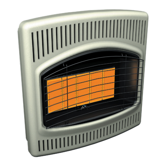
UNVENTED (VENT-FREE) INFRARED GAS HEATER
SAFETY INFORMATION AND INSTALLATION MANUAL
CRP26, CRP26T, CRT26PT, CRN30, CRN30T, CRT30NT
WARNING: If the information in this manual is not fol-
lowed exactly, a fire or explosion may result causing
property damage, personal injury or loss of life.
— Do not store or use gasoline or other flammable
vapors and liquids in the vicinity of this or any other
appliance.
— WHAT TO DO IF YOU SMELL GAS
• Do not try to light any appliance.
• Do not touch any electrical switch; do not use any
phone in your building.
• Immediately call your gas supplier from a neighbor's
phone. Follow the gas supplier's instructions.
• If you cannot reach your gas supplier, call the fire
department.
— Installation and service must be performed by a quali-
fied installer, service agency or the gas supplier.
For more information, visit www.desatech.com
Model CRN30 Shown
CRP16, CRP16T, CRN18, CRN18T
Save this manual for future reference.
Advertisement
Table of Contents

Related Manuals for Comfort Glow CRP16, CRP16T, CRN18, CRN18T CRP26


Summary of Contents for Comfort Glow CRP16, CRP16T, CRN18, CRN18T CRP26
- Page 1 UNVENTED (VENT-FREE) INFRARED GAS HEATER SAFETY INFORMATION AND INSTALLATION MANUAL Model CRN30 Shown CRP16, CRP16T, CRN18, CRN18T CRP26, CRP26T, CRT26PT, CRN30, CRN30T, CRT30NT WARNING: If the information in this manual is not fol- lowed exactly, a fire or explosion may result causing property damage, personal injury or loss of life.
-
Page 2: Table Of Contents
WARNING: Improper installation, adjustment, altera- tion, service or maintenance can cause injury or prop- erty damage. Refer to this manual for correct installation and operational procedures. For assistance or addi- tional information consult a qualified installer, service agency or the gas supplier. WARNING: This is an unvented gas-fired heater. -
Page 3: Safety Information
SAFETY INFORMATION Due to high temperatures, the appliance should be located out WARNING: This product con- of traffic and away from furniture tains and/or generates chemicals and draperies. known to the State of California to cause cancer or birth defects Do not place clothing or other or other reproductive harm. -
Page 4: Product Identification
SAFETY INFORMATION Continued 5. Always run heater with plaque control knob Control Knob & Ignitor Button Heater at the 1, 2, 3 or 4 locked positions. Never (not seen from this view) Cabinet set control knob between locked positions. Poor combustion and higher levels of carbon monoxide may result. -
Page 5: Air For Combustion And Ventilation
AIR FOR COMBUSTION Unusually tight construction is defined as construction where: AND VENTILATION a. walls and ceilings exposed to the out- side atmosphere have a continuous WARNING: This heater shall water vapor retarder with a rating of not be installed in a confined one perm (6 x 10 kg per pa-sec-m ) or... -
Page 6: Air For Combustion
AIR FOR COMBUSTION C. Install a lower Btu/Hr heater, if lower Btu/Hr size makes room unconfined. AND VENTILATION If the actual Btu/Hr used is less than the maximum Continued Btu/Hr the space can support, the space is an un- confined space. You will need no additional fresh Determine the volume of the space (length x air ventilation. -
Page 7: Installation
AIR FOR COMBUSTION CHECK GAS TYPE Use only the correct type of gas (natural or pro- AND VENTILATION pane/LP). If your gas supply is not the correct gas Continued type, do not install heater. Call dealer where you Ventilation Air From Outdoors bought heater for proper type heater. - Page 8 INSTALLATION An optional fan kit is available from your dealer. See Accessories, page 23. If planning to use fan, Continued locate heater near an electrical outlet. You can locate heater on the floor, away from a wall. A wall mounting bracket and floor base stand THERMOSTAT SENSING BULB are included with this heater.
- Page 9 INSTALLATION 16" 14" Min. Continued Methods For Attaching Mounting Bracket To Wall Only Insert Mounting " Only use last hole on each end of mounting bracket Screws Through Last Min. to attach bracket to wall. These two holes are 14 Hole On Each End inches apart from their centers.
- Page 10 INSTALLATION Continued 3. Insert wall anchor (wings first) into hole. Tap anchor flush to wall. 4. For thin walls (1/2" or less), insert red key into wall anchor. Push red key to “pop” open anchor wings. IMPORTANT: Do not hammer key! For thick walls (over 1/2"...
- Page 11 INSTALLATION CONNECTING TO GAS SUPPLY Continued WARNING: This appliance MOUNTING HEATER TO FLOOR requires a 3/8" NPT (National Mounting Base Feet to Heater Pipe Thread) inlet connection to 1. Lay heater cabinet on its back on a table with the pressure regulator. the heater bottom overhanging the table edge.
- Page 12 INSTALLATION Pressure Regulator Continued CAUTION: Use only new, black iron or steel pipe. Inter- Heater Cabinet nally-tinned copper tubing may be used in certain areas. Check Tee Joint Equipment your local codes. Use pipe of Reducer Shutoff large enough diameter to allow Bushing to Valve * proper gas volume to heater.
- Page 13 INSTALLATION 4. Check all joints from equipment shutoff valve to thermostat gas valve (see Figure 17 or 18). Continued Apply a noncorrosive leak detection fluid to PRESSURE TESTING GAS SUPPLY all joints. Bubbles forming show a leak. PIPING SYSTEM 5. Correct all leaks at once. Test Pressures In Excess Of 1/2 PSIG 6.
-
Page 14: Operating Heater
5. Turn control knob to PILOT/IGN and press in. Note: You may be running this heater for the first time after hooking up to gas supply. If so, you may need to press in control knob for 30 seconds or more. This will allow air to bleed from the gas system. - Page 15 MANUAL LIGHTING OPERATING HEATER PROCEDURE Continued 1. Remove front panel (see Figure 7, page 8). TO SELECT 2. Follow steps 1 through 5 under Lighting HEATING LEVEL Instructions, page 14. 3. With control knob pressed in, strike match. WARNING: When running Hold match to pilot until pilot lights.
- Page 16 OPERATING HEATER 8. Turn thermostat control knob counter- clockwise to the desired heating level. Continued The main burner should light. Set control LIGHTING knob to any heat level between 1 and 5 (see INSTRUCTIONS Figure 24). 1. STOP! Read the safety information, page 15, column 2.
-
Page 17: Inspecting Heater
OPERATING HEATER Note: The pilot flame on natural gas units will have a slight curve, but flame should be blue and Continued have no yellow or orange color. THERMOSTAT Blue Flame OPERATION The thermostatic control used on these models Pilot Burner Thermocouple differs from standard thermostats. -
Page 18: Cleaning And Maintenance
CLEANING AND 4. Never insert objects into the pilot tube. Clean the pilot assembly also. A yellow tip on the MAINTENANCE pilot flame indicates dust and dirt in the pilot as- sembly. There is a small pilot air inlet about two WARNING: Turn off heater inches from where the pilot flame comes out of and let cool before cleaning. -
Page 19: Troubleshooting
TROUBLESHOOTING WARNING: Turn off and unplug heater and let cool before servicing. Only a qualified service person should service and repair heater. CAUTION: Never use a wire, needle or similar object to clean ODS/pilot. This can damage ODS/pilot unit. Note: All troubleshooting items are listed in order of operation. OBSERVED PROBLEM POSSIBLE CAUSE REMEDY... - Page 20 TROUBLESHOOTING Continued OBSERVED PROBLEM POSSIBLE CAUSE REMEDY ODS/pilot lights but flame 1. Control knob not fully pressed in 1. Press in control knob fully goes out when control knob is 2. Control knob not pressed in 2. After ODS/pilot lights, keep con- released long enough trol knob pressed in 30 seconds...
- Page 21 TROUBLESHOOTING Continued WARNING: If you smell gas • Shut off gas supply. • Do not try to light any appliance. • Do not touch any electrical switch; do not use any phone in your building. • Immediately call your gas supplier from a neighbor’s phone. Fol- low the gas supplier’s instructions.
-
Page 22: Specifications
SPECIFICATIONS CRN18, CRN18T CRN30, CRN30T CRT30NT Btu (Variable) 6,600/12,000/18,000 6,600/18,000/30,000 6,600/18,000/30,000 Type Gas Natural Only Natural Only Natural Only Ignition Piezo Piezo Electronic Pressure Regulator Setting 6" W.C. 6"W.C. 6" W.C. Inlet Gas Pressure* (in. of water) Maximum 10.5" 10.5" 10.5"... -
Page 23: Accessories
ACCESSORIES REPLACEMENT PARTS Purchase these heater accessories from your local Note: Use only original replacement parts. This dealer. If they can not supply these accessories, either will protect your warranty coverage for parts contact your nearest Parts Central (see page 31) or replaced under warranty. -
Page 24: Illustrated Parts Breakdown And Parts List
ILLUSTRATED PARTS BREAKDOWN CABINET BODY MODELS CRP16, CRN18, CRP16T, CRN18T, CRP26, CRN30, CRP26T and CRN30T Thermostat Manual models only models only See Pages 28 through 31 www.desatech.com 107883-01H... -
Page 25: Parts List
PARTS LIST This list contains replaceable parts used in your heater. When ordering parts, follow the instructions listed under Replacement Parts on page 23 of this manual. PART NUMBER KEY CRP16 CRP16T CRP26 CRP26T CRN18 CRN18T CRN30 CRN30T DESCRIPTION 107954-01 107954-01 107955-01 107955-01 Front Panel 107879-02 107879-02 107879-01 107879-01 Grill Guard ____ ____... - Page 26 ILLUSTRATED PARTS BREAKDOWN CABINET BODY MODELS CRT26PT AND CRT30NT See Pages See Pages 26 and 27 30 and 31 Install Battery According To This Illustration (Determine which ignitor your heater uses) Battery Positive Battery Negative www.desatech.com 107883-01H...
- Page 27 PARTS LIST This list contains replaceable parts used in your heater. When ordering parts, follow the instructions listed under Replacement Parts on page 23 of this manual. PART NUMBER CRT26PT CRT30NT DESCRIPTION QTY. 107955-03CV 107955-03CV Front Panel 107879-01 107879-01 Grill Guard 102394-02 102394-02 Thermostat Valve Mounting Bracket...
- Page 28 ILLUSTRATED PARTS BREAKDOWN BURNER ASSEMBLY MODELS CRP16, CRN18, CRP26 AND CRN30 ODS/Pilot Burner Assembly CRP16 and CRN18 Burner Assembly CRP26 and CRN30 www.desatech.com 107883-01H...
- Page 29 PARTS LIST This list contains replaceable parts used in your heater. When ordering parts, follow the instructions listed under Replacement Parts on page 23 of this manual. PART NUMBER CRP16 CRN18 CRP26 CRN30 DESCRIPTION QTY. 110803-02* 110803-03* 110803-02* 110803-03* ODS/Pilot 110186-01 110186-01 110186-01...
- Page 30 ILLUSTRATED PARTS BREAKDOWN BURNER ASSEMBLY MODELS CRP16T, CRN18T, CRP26T, CRT26PT, CRN30T AND CRT30NT ODS/Pilot Burner Assembly CRP16T and CRN18T Burner Assembly CRP26T, CRT26PT, CRN30T and CRT30NT www.desatech.com 107883-01H...
-
Page 31: Parts Central
PARTS LIST This list contains replaceable parts used in your heater. When ordering parts, follow the instructions listed under Replacement Parts on page 23 of this manual. PART NUMBER CRP26T CRN30T CRP16T CRN18T CRT26PT CRT30NT DESCRIPTION QTY. 110803-02* 110803-03* 110803-02* 110803-03* ODS/Pilot 110186-01 110186-01 110186-01 110186-01 Thermocouple Kit 099387-11 099387-11 099387-03 099387-03 Pilot Tubing 104818-03 104818-03 104818-04 104818-04 Outlet Tubing... -
Page 32: Warranty Information
WARRANTY INFORMATION KEEP THIS WARRANTY Model Serial No. Date Purchased Always specify model and serial numbers when communicating with the factory. We reserve the right to amend these specifications at any time without notice. The only warranty applicable is our standard written warranty.
Need help?
Do you have a question about the CRP16, CRP16T, CRN18, CRN18T CRP26 and is the answer not in the manual?
Questions and answers