Table of Contents
Advertisement
D
L
E
S
I
G
N
E
D
T
O
E
A
D
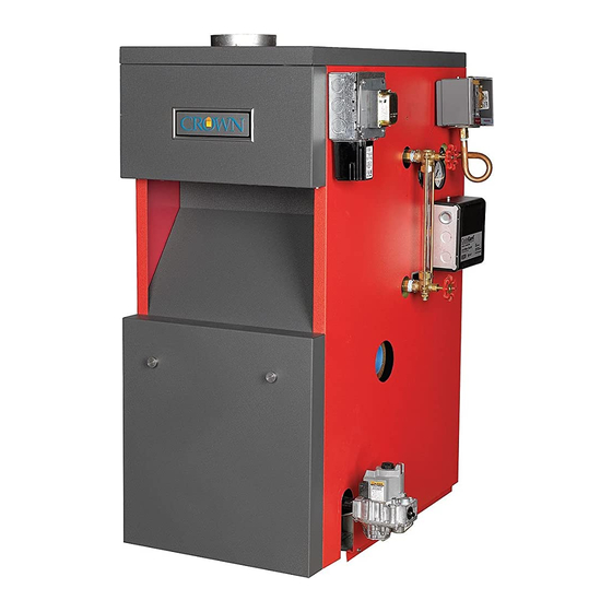
Series 32
Gas-Fired Natural Draft Steam or Water Boilers
INSTALLATION AND OPERATING INSTRUCTIONS
These instructions must be affixed on or adjacent to the boiler.
WARNING: Improper installation,
adjustment, alteration, service or
maintenance can cause property
damage, injury, or loss of life. For
assistance or additional information,
consult a qualified installer, service
agency or the gas supplier. Read
these instructions carefully before
installing.
Manufacturer of Hydronic Heating Products
P.O. Box 14818 3633 I. Street
Philadelphia, PA 19134
Tel: (215) 535-8900 • Fax: (215) 535-9736 • www.crownboiler.com
1
Advertisement
Table of Contents

Related Manuals for Crown Boiler 32 Series


Summary of Contents for Crown Boiler 32 Series
-
Page 1: Installation And Operating Instructions
Series 32 Gas-Fired Natural Draft Steam or Water Boilers INSTALLATION AND OPERATING INSTRUCTIONS These instructions must be affixed on or adjacent to the boiler. WARNING: Improper installation, adjustment, alteration, service or maintenance can cause property damage, injury, or loss of life. For assistance or additional information, consult a qualified installer, service agency or the gas supplier. -
Page 3: Table Of Contents
Table of Contents Product Description Specifications III. Before Installing Locating the Boiler Knockdown Boiler Assembly Instructions 10 Air for Combustion & Ventilation VII. Venting VIII. Steam Boiler Piping & Trim Installation A. Heating System Piping B. Indirect Water Heater Piping Water Boiler Piping A. -
Page 4: Specifications
II Specifications... - Page 6 NAT URAL GAS ONLY WAT ER WAT ER NUMBER I=B=R NET RAT ING BASIC BOILER HEAT ING VOL. VOL. INPUT Combustion MODEL CAPACIT Y OUT PUT Steam Water SECT IONS Effy. % (MBH) (MBH) (Sq. ft) (MBH) (MBH) (Gal) (Gal) 32-475W(S)N 1188 80-1/2...
-
Page 9: Before Installing
III Before Installing 1) Safe, reliable operation of this boiler depends upon installation by a professional heating contractor in strict accordance with this manual and the requirements of the authority having jurisdiction. • In the absence of an authority having jurisdiction, installation must be in accordance with this manual and the latest edition of the National Fuel Gas Code, ANSI Z223.1. - Page 10 Ove r All M inim um Ove r All Ove r All Height Boiler Boile r Room Length Depth Floor To Volum e Model Volum e Jacke t Jacke t Top Of (Ft3) (Ft3) Jacke t 32-475 36 3/4 32 1/4 46 5/8 32.0 511.7...
- Page 11 Minimum Clearance - Jacket Clearances Required For Removal Of Tankless Heater Service Clearance To Non- To Combustible Or Non- Combustible Construction Combustible Construction Left Side 24" 18" (Controls) 27" 32" 42" Right Side 24" 18" (Controls) 27" 32" 42" Front 24"...
-
Page 12: Knockdown Boiler Assembly Instructions
V Knockdown Boiler Assembly Instructions A. Prior To Assembly 1) Thoroughly inspect the cast iron heat exchanger sections for any shipping damage, i.e. cracks in the castings, broken lugs or punctures due to mishandling. 2) Do not use a damaged heat exchanger section. Replace it with an undamaged heat exchanger section. 3) Keep the base in the shipping carton until it is time to perform the assembly. - Page 14 C. Section Assembly 1) Clean the boiler sections inside and out to remove dirt due to shipping and handling. 2) Clean all nipples and nipple ports with kerosene immediately prior to section assembly. 3) Set the left end section on the base so that the locating lugs on the bottom of the section go inside the front and rear base panels.
- Page 15 Figure 5: Use Of Nipple Gauge Figure 6: Assembly Of Sections...
- Page 16 14) Install the tankless coil/s and/or cover plates using the gaskets and 3/8 x 7/8 bolts and washers provided (see Figure 7). 15) Test assembled block for leaks. Unless local codes have other requirements, use the following procedure: a) Run a hose from the water service to one of the lower tappings. Install a ball or gate valve in one of the tappings on the top of the block and connect the other end of this valve to a drain.
- Page 17 NOTE Installation of the draft hoods will be easier if one person supports the rear of the hood while another installs the carriage bolts, nuts and washers. 6) Hang a rear tie rod channel bracket on the 4" stud installed in the left end section (Figure 12a). 7) Facing the rear of the boiler, find the square mounting holes underneath the draft hood.
- Page 18 Figure 11: Front Attachment Of Draft Hood Figure 12a: Mounting Rear Tie Rod Channel Bracket Figure 12b: Rear Attachment Of Draft Hood...
- Page 19 D. Jacket Assembly Instructions NOTE Before installing the jacket, make sure to plug any tappings which are not going to be used. Also make sure that no tappings are plugged which will be needed later for piping the boiler. See Sections VIII and IX for piping and trim installation.
-
Page 21: Air For Combustion & Ventilation
VI Air For Combustion and Ventilation Sufficient fresh air must be supplied for combustion, ventilation and flue gas dilution. Provisions for combustion, ventilation and flue gas dilution air for gas utilization equipment vented by natural draft must be made in accordance with local building codes or, in absence of such codes, in accordance with the National Fuel Gas Code, NFPA 54/ANSI Z223.1. - Page 22 Figure 15: Boiler Installed In Confined Space, All Air From Inside • If providing openings into adjacent rooms is undesirable, combustion and ventilation air can be brought into the boiler room from outdoors. See the instructions under “For Buildings of Unusually Tight Construction”. B.
- Page 23 Figure 16: All Air From Outdoors, Ventilated Crawl Space & Attic Figure 17: All Air From Outdoors, Via Ventilated Attic Figure 18: All Air From Outdoors, Using Openings Into Boiler Room...
- Page 24 Figure 19: All Air From Outdoors, Using Horizontal Ducts Into The Boiler Room...
-
Page 25: Venting
VII Venting Vent installation must be in accordance with local building codes, or the authority having jurisdiction, or the National Fuel Gas Code, NFPA 54/ANSI Z223.1. Typical vent installations are shown in Figures 20 and 21. The vent system shown in Figure 20 uses a common vent for all boiler modules. - Page 26 6) Lateral venting should slope upwards towards the chimney not less than one inch in four feet. No portion of vent pipe should run downward or have sags. Vent pipe must be securely supported. 7) The connector rise coming off the boiler should be as tall as possible, while still maintaining the proper clearance from the horizontal vent connector to combustibles and the proper pitch called for in (6) above.
- Page 27 Figure 20: Typical Series 32 Venting (Common Module Venting) Figure 21: Series 32 Venting (Each Module Individually Vented)
- Page 28 Removing An Existing Boiler From A Common Chimney In some cases, when an existing boiler is removed from a common chimney, the common venting system may be too large for the remaining appliances. At the time of removal of an existing boiler, the following steps shall be followed with each appliance remaining connected to the common venting system placed in operation, while the other appliances remaining connected to the common venting system are not in operation.
-
Page 29: Steam Boiler Piping & Trim Installation
VIII Steam Boiler Piping & Trim Installation CAUTION • INSTALL BOILER SO THAT THE GAS IGNITION SYSTEM COMPONENTS ARE PROTECTED FROM WATER (DRIPPING, SPRAYING, RAIN, ETC.) DURING APPLIANCE OPERATION AND SERVICE (CIRCULATOR REPLACEMENT, ETC.). • OPERATION OF THIS BOILER IN A SYSTEM HAVING SIGNIFICANT AMOUNTS OF DISSOLVED OXYGEN CAN CAUSE SEVERE HEAT EXCHANGER CORROSION DAMAGE. - Page 30 Hydrolevel CG450 – This is a probe type LWCO and is installed in tapping “G”. On the CSD-1 control package, and other boilers with redundant low water cut-offs, the CG450 is the operating low water cut-off and should be used to control a feeder (if used). The CG450 supplied with the Series 32 uses a special probe which does not have a mounting flange.
- Page 31 Figure 22: Steam Boiler Tapping Locations Tapping Uses Chart For Steam Boilers Component Description Tapping Tapping Standard CSD-1 Location Size (in) Equipment Package Supply Piping Return Piping Safety Relief Valves 1-1/2 (With Inlet Opening Up To & Including 1-1/2" NPT Inlet) Safety Relief Valves Riser (See Figure 27c)
- Page 32 Boiler Drain Valve - Install with a 3” x ¾” bushing into one of the two return tappings “B”. The drain valve may also be installed in the return piping, but it must be installed in the leg of a tee so that it is directly opposite and as close as possible to the return tapping.
- Page 33 Figure 25: Common Near-Boiler Piping Mistakes Steam Steam Return Condensate Equalizer Boiler Header Riser Pipe Header Return Pipe Pipe Model Size (in) Quantity Size (in) Size (in) Quantity Size (in) Quantity Size (in) 32-380 1 1/2 1 1/2 32-475 1 1/2 1 1/2 32-570 1 1/2...
-
Page 38: Indirect Water Heater Piping
B. Indirect Water Heating Piping (Steam Boilers) The steam version of the Series 32 boiler is equipped with tappings to permit the connection of a Crown Mega-Stor, or other indirect water heater. In this type of system, hot boiler water is drawn from below the water line and passed through the heat exchanger in the indirect water heater. -
Page 39: Water Boiler Piping
IX Water Boiler Piping CAUTION • INSTALL BOILER SO THAT THE GAS IGNITION SYSTEM COMPONENTS ARE PROTECTED FROM WATER (DRIPPING, SPRAYING, RAIN, ETC.) DURING APPLIANCE OPERATION AND SERVICE (CIRCULATOR REPLACEMENT, ETC.). • OPERATION OF THIS BOILER WITH CONTINUOUS RETURN TEMPERATURES BELOW 120°F CAN CAUSE SEVERE HEAT EXCHANGER CORROSION DAMAGE. - Page 40 DANGER • CONFIRM RELIEF VALVE HAS THE CORRECT PRESSURE SETTING AND CAPACITY FOR THE BOILER. • PIPE THE PRESSURE RELIEF VALVE DISCHARGE TO A SAFE LOCATION. • DO NOT INSTALL A VALVE IN THE RELIEF VALVE DISCHARGE LINE. • DO NOT PLUG RELIEF VALVE DISCHARGE. 3) In addition to the boiler trim, the following system components are required: a.
- Page 41 Figure 29: Water Boiler Tapping Locations Tapping Uses Chart For Water Boilers Component Description Tapping Tapping Standard CSD-1 Location Size (in) E quipment Package Supply Piping Return Piping Pressure Relief V alves 1-1/2 Combination Pressure / Temperature / A ltitude Gauge Hydrolevel #750 Probe Low W ater Cut-Off Supply Riser Honeywell L4006A Pressure Limit Control...
- Page 43 Supply Supply Water Return Return Water Boiler Header Riser Connections Header Connections Model Size (in) Quantity Size (in) Size (in) Quantity Size (in) 32-475 32-570 32-665 2 1/2 2 1/2 2 1/2 2 1/2 32-760 2 1/2 2 1/2 2 1/2 2 1/2 32-855 2 1/2...
-
Page 44: Tankless Heater Piping
B. TANKLESS HEATER PIPING If the Series 32 water boiler is installed with an optional tankless heater, pipe the heater as shown in Figure 32. The components in this system and their functions are as follows: 1) Mixing Valve (Required) - During the heating season, the water exiting the tankless heater may be 180 degrees or more. - Page 45 8) Multiple Tankless Heaters - If two tankless heaters are installed in the boiler, it is recommended that each heater be installed in parallel with its own mixing valve, relief valve, flow restrictor, etc.. This will permit either heater to be removed from service for maintenance while still providing some domestic water to the building.
-
Page 46: Gas Piping
X Gas Piping 1) Gas piping to the boiler must be sized to deliver an adequate supply of gas for the boiler to fire at the nameplate input with the inlet pressure at the gas valves between the minimum and maximum valves shown on the rating plate. -
Page 47: Control System Wiring
XI Control System Wiring WARNING All wiring and grounding must be done in accordance with the authority having jurisdiction or, in the absence of such requirements, with the National Electrical Code (ANSI/NFPA 70). 1) Provide the boiler with a dedicated branch circuit with a fused disconnect. The minimum rating of this circuit must be 15A. -
Page 48: Csd-1 Steam / Water
6) Once the ignition module detects the presence of a pilot flame, voltage is applied across the main valve, opening the valve and establishing main flame. 7) The way in which the ignition module handles failure to establish pilot or the loss of an already established pilot depends upon the exact ignition module supplied with the boiler. - Page 49 Figure 35: Series 32 Standard Boiler Wiring...
- Page 50 Figure 36: Series 32 - CSD-1 Boiler Wiring...
- Page 51 Safety Control Operation Temperature Limit Control (Water Boilers) – The temperature limit control interrupts burner operation when the supply water temperature exceeds the set point. Maximum allowable water temperature in a water boiler is 250F. The L4006A will reset itself when the water temperature drops below the set point less the differential (typically 15F). Manual reset water limit controls, such as the Honeywell L4006E, must be manually reset.
-
Page 52: Start-Up & Checkout
XII Start-up and Checkout NOTE SAFE LIGHTING AND OTHER PERFORMANCE CRITERIA WERE MET WITH THE GAS MANIFOLD AND CONTROL ASSEMBLY PROVIDED ON THE BOILER WHEN THE BOILER UNDERWENT THE TESTS SPECIFIED IN Z21.13. Use the following procedure for initial start-up of the boiler: 1) Make sure that the boiler is filled with water. - Page 53 WARNING FAILURE TO FOLLOW THE FOLLOWING PROCEDURE EXACTLY COULD RESULT IN OVER-FIRING OF THE BOILER AND A CARBON MONOXIDE HAZARD. 13) Check the manifold pressure and adjust if necessary. To do this, use the following procedure: Connect a manometer to the inlet pressure tap on the gas valve (see Figures 39 - 41). b.
- Page 54 16) (Steam Boilers) - Verify low water cutoff operation while the boiler is running. Slowly open drain valve and drain boiler until the water level drops below low water cutoff line. Water still should be visible in the gauge glass when the low water cutoff shuts down the main burners.
- Page 55 Figure 39: Gas Valve Detail - Honeywell VR8304 Figure 40: Gas Valve Detail - Robertshaw 7000DERHC Figure 41: CSD-1 Gas Train...
-
Page 56: Operating Instructions
LIGHTING INSTRUCTIONS FOR BASE MODULES EQUIPPED WITH HONEYWELL VR8304 SERIES GAS VALVES FOR YOUR SAFETY READ BEFORE LIGHTING WARNING: If you do not follow these instructions exactly, a fire or explosion may result causing property damage, personal injury or loss of life. A. - Page 57 LIGHTING INSTRUCTIONS FOR BASE MODULES EQUIPPED WITH ROBERTSHAW 7000DERHC SERIES GAS VALVES FOR YOUR SAFETY READ BEFORE LIGHTING WARNING: If you do not follow these instructions exactly, a fire or explosion may result causing property damage, personal injury or loss of life. A.
-
Page 58: Service & Maintenance
XIII Service and Maintenance The following routine maintenance should be performed: On a continuous basis: 1) Keep the area around the boiler free and clear from combustible materials, gasoline, and other flammable vapors and liquids. 2) Keep the area around the boiler and boiler room ventilation openings clear of objects which might obstruct the flow of combustion and ventilation air. - Page 59 12) Place the boiler back in operation using the procedure outlined in “Start-up”. Check the pilot line and any other gas piping disturbed during the inspection process for leaks. Heat Exchanger Cleaning Procedure 1) Turn off electrical power and gas supply to the boiler 2) Disconnect the vent connectors from the boiler.
-
Page 60: Parts & Cartons Contents
XIV PARTS The following parts may be obtained from any Crown distributor. To find the closest Crown distributor, consult the area Crown representative or the factory at: Crown Boiler Co. Customer Service P.O. Box 14818 Philadelphia PA. 19134 (215) 535-8900 www.crownboiler.com... - Page 61 STEAM) (STD CARTON BOILER WATER) (STD CARTON BOILER CARTON TRIM STEAM CARTON TRIM WATER CARTON PANEL SIDE JACKET CARTON PANEL SIDE BASE BOILERS) (STEAM INTERMEDIATE TAPPED BOILERS) (STEAM INTERMEDIATE BOILERS) (WATER INTERMEDIATE BOILERS) (ALL LEFT BOILERS) (ALL RIGHT...
- Page 62 TANKLESS COILS PARTS PART # MODEL 310020 310021 310022 BASE CARTON QUANTITY DESCRIPTION PART # 285 BASE ASSEMBLY (STD) 310114 380 BASE ASSEMBLY (STD) 310115 475 BASE ASSEMBLY (STD) 310116 285 BASE ASSEMBLY (CSD-1) 3101145 380 BASE ASSEMBLY (CSD-1) 3101155 475 BASE ASSEMBLY (CSD-1) 3101165 REAR TIE ROD CHANNEL BRACKET...
- Page 63 SECTION JOINER CARTON QUANTITY DESCRIPTION PART # "A" "B" "C" "D" "E" 7" PUSHNIPPLE 310005 3" PUSHNIPPLE 310006 5/8 X 9 3/4 TIE ROD 900310 5/8 HEX NUT 900311 5/8 FLAT WASHER 900312 LOCTITE # 592, 50 ml TUBE 900350 LOCTITE # 592, 250 ml TUBE 900355 "SECTION SEAL", 1 QUART CAN...
- Page 64 BASE PARTS QTY PER BASE MODULE DESCRIPTION PART # BASE FRONT PANEL (285) 310604 BASE FRONT PANEL (380) 310605 BASE FRONT PANEL (475) 310606 BASE FRONT LEG (RH) 310110 BASE FRONT LEG (LH) 310111 INSULATION BASE FRONT (285) 312614 INSULATION BASE FRONT (380) 312615 INSULATION BASE FRONT (475) 312616...
- Page 66 BASE PARTS (CONTD.) QUANTITY DESCRIPTION PART # MANIFOLD ASSY, COMPLETE (285) 310154 MANIFOLD ASSY, COMPLETE (380) 310155 MANIFOLD ASSY, COMPLETE (475) 310156 1/4-20 X 1/2 SELF TAPPING SCREW 900100 MAIN BURNER LESS PILOT BRKT 150321 MAIN BURNER WITH PILOT BRKT. 150320 PILOT ASSY, Q362A1037 3504060...
- Page 68 WATER TRIM CARTON DESCRIPTION PART # L4006A2015 35-3510 L4006E1109 MAN. RESET (CSD-1 ONLY) 35-3100 1/2 LONG WELL 35-1006 HYDROLEVEL 550 LWCO (CSD-1 ONLY) 450550 1-1/2 X 1/2 BLK BUSHING 950021 TRIDICATOR GAUGE 95-038 1/2 X 1/4 BLK BUSHING 95-053 BLANK COIL PLATE 270003 COIL GASKET 270001...
- Page 69 NIPPLE 1-1/4 95-031 ELBOW 1-1/4 95-058 NIPPLE 1-1/4 95-033 BUSHING 1-1/4 1-1/2 95-047 NIPPLE 950110 ELBOW 950190 NIPPLE 950114 BUSHING 1-1/2 950185 NIPPLE 95-105 ELBOW 95-057 NIPPLE 95-027 BUSHING 1-1/2 95-096 10-616-05 CONBRACO VALVE, RELIEF 950500 10-615-05 CONBRACO VALVE, RELIEF 95-134 10-614-05 CONBRACO...
- Page 70 BUSHING 1-1/4 1-1/2 95-047 BUSHING 1-1/2 950185 BUSHING 1-1/2 95-096 PLUG 1-1/2 950170 COUPLING 1-1/2 950175 1-1/2 950180 NIPPLE 1-1/2 950124 12-205 CONBRACO VALVE, SAFETY 950530 13-214 CONBRACO VALVE, SAFETY 950525 13-213 CONBRACO VALVE, SAFETY 950520 13-202 CONBRACO VALVE, SAFETY 950515 13-211 CONBRACO...
- Page 71 Manufacturer of Hydronic Heating Products P.O. Box 14818 3633 I. Street Philadelphia, PA 19134 Tel: (215) 535-8900 • Fax: (215) 535-9736 • www.crownboiler.com PN 980888 Rev.2 10/08...
Need help?
Do you have a question about the 32 Series and is the answer not in the manual?
Questions and answers