Subscribe to Our Youtube Channel
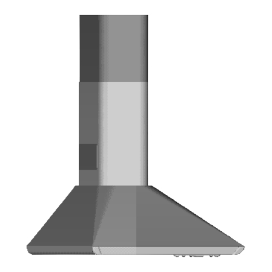
Summary of Contents for Ariston HD6
- Page 1 Istruzioni per l'uso Dir. 89/336/CEE Operating instructions 73/23/CEE Mode d'emploi Bedienungsanleitung Gebruiksaanwijzing Manual de instrucciones Manual de instruções 4324175 - 12/98...
-
Page 2: Istruzioni Per L'installazione
3.6 - Non fare cucine alla fiamma sotto la cappa. sulla linea verticale. fissaggio delle staffe come indicato nel paragrafo ISTRUZIONI PER Parte 1ª 4.1 2. b - Segnare sulla parete i due fori asolati della 3.7 - Controllare le friggitrici durante l’uso: l’olio L’INSTALLAZIONE staffa. -
Page 3: Istruzioni Per L'uso E La Manutenzione
c - Collegare il raccordo aspirante A alla tuba- 3 - MANUTENZIONE tivo posti alle estremità del diffusore girandoli ISTRUZIONI PER Parte 2ª zione di evacuazione esterna, utilizzando il nel verso delle frecce A. Rimontare i nuovi fil- L’USO E LA Una costante manutenzione garantisce un buon tubo rettangolare 90x132. -
Page 4: Installation Instructions
3.4 - The appliance must be earthed. the correct figure can only be obtained by ensure the correct vertical alignment of the wall INSTALLATION Part 1 measuring the actual height of the splash- fixing brackets. 3.5 - When istalled, the hood must be positioned INSTRUCTIONS back to be fitted. -
Page 5: Operation
above the hotplate. The grilles are marked with two arrows and Position 1 = low speed, should be selected when pushing the wire clips to one side and removing b - Connect the air outlet collar to the ducting should be fitted with one arrow pointing upwards simmering or using only one pan;... -
Page 6: Instructions Pour L'installation
1ère Partie 3.5 - La distance de sûreté minimum entre le plan trous pour fixer les brides 1 à une distance avoir des valeurs différentes selon les dimen- Y = 100 mm entre le centre des deux trous sions de la demi-cheminée et correspond à la de cuisson et la hotte est de 65 cm. -
Page 7: Entretien
a - Percez un trou de 120 mm Ø dans la planche 3 - Encliquetez les deux petites grilles dans leur 2 - UTILISATION et assurez-vous que les crochets soient bien placée entre les deux armoires. logement de façon à ce que le symbole soit placés dans leur logement. -
Page 8: Montage Des Gerätes
3.7 - Frittiergeräte, die unter der Dunstesse betrieben 4.3 - Elektrischer Anschluß und Funktionskontrolle und sollte von entsprechend geschulten Personen MONTAGEHINWEISE Teil 1 werden, sind während der gesamten Betriebs- 4.4 - Anschluß für Abluft- oder Umluftbetrieb vorgenommen werden. Wenn man sich auf die dauer zu beaufsichtigen. -
Page 9: Wartung Und Pflege
(Motor und Beleuchtung) ist dem Typenschild zu c - Obere Stellung (Abb. 9): Die Verlängerung 1.2 - Niemals eine große Flamme bei eingeschal- Bemerkung: Dieser Filter kann nicht ausgewa- P wird mit dem runden Gebläseausgang teter Dunsthaube unbedeckt lassen. Wenn der entnehmen. -
Page 10: Instructies Voor De Installatie
3.4 - Vergewis U ervan dat het elektriciteitsnet in maat dient direct te worden genomen op d - De eventuele stabilisatie van het onderste INSTRUCTIES Eerste deel het bijgeleverde ruggedeelte, aangezien er huis een correcte aarding heeft. deel wordt, indien nodig, overgelaten aan VOOR DE verschillende soorten ruggedeelten worden de installateur. -
Page 11: Waarschuwingen Voor De Veiligheid
Voor de installatie van de buis Ø 120 mm, slag. Bevestig de halve buis aan de beugels 1.3 - Regel de vlam altijd zodanig dat deze niet verliezen. De fabrikant wijst ieder aanspra- 2 met vier van de bij de accessoires gele- is het noodzakelijk de reduceerflens K op aan de zijkant van de pan omhoog komt:... -
Page 12: Instrucciones De Instalacion
3.7 - Controlar las freidoras durante su uso: el dola con la línea vertical a una distancia sobre la línea vertical. INSTRUCCIONES Parte 1ª medida como se indica en la fig. 2. La me- aceite demasiado caliente podría incendiarse. b - Marcar en la pared los dos agujeros de la DE INSTALACION dida debe ser igual a la altura del tubo su- placa. -
Page 13: Mantenimiento
También en este caso los tubos y las fajillas 3 - MANTENIMIENTO situados en las extremidades del difusor metálico INSTRUCCIONES Parte 2ª deberan ser adquiridos por el instalador. girándolos en el sentido de las flechas A. Volver Una mantenimiento constante garantiza un buen DE USO Y d - Quitar los filtros de carbón (ver parrafo 3.3 a montar los filtros girándolos en el sentido de... -
Page 14: Instruções Paraa Instalação
3.5 - A distância mínima de segurança entre a 3 - Colocação dos estribos 2 O valor da cota X pode variar em função das INSTRUÇÕES PARA 1ª Parte várias dimensões disponíveis do semitu- mesa de cozedura e a coifa é de 65 cm. a - Apóie um dos estribos 2 na parede a cerca A INSTALAÇÃO de 1 ou 2 mm do tecto ou do limite superior,... -
Page 15: Precauções De Segurança
2 - Conexão da versão aspirante seu curso. Não se esqueça que, na sua base, o 2 - UTILIZAÇÃO - Substititua o filtro de forma que os pontos (instalação tipo C) perímetro do semitubo deverá ser introduzido coloridos fiquem virados para a grade. Quadro de comandos (fig. - Page 16 Fig. 4 Fig. 3 Fig. 1 Fig. 7 Fig. 5 Fig. 6 Fig. 2...
- Page 17 Fig. 13 Fig. 8 1 2 3 Fig. 14 Fig. 16a Fig. 15 Fig. 9 Fig. 10 Fig. 16b Fig. 16c Fig. 12 Fig. 11...
- Page 18 Fig. 17 Fig. 18...


Need help?
Do you have a question about the HD6 and is the answer not in the manual?
Questions and answers