Table of Contents
Advertisement
Advertisement
Table of Contents

Related Manuals for Chicago Electric 68887


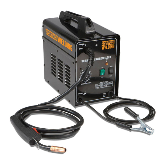
Summary of Contents for Chicago Electric 68887
-
Page 2: Important Safety Information
Table of Contents Safety ............2 Welding Tips ..........18 Specifications ..........7 Maintenance ..........22 Setup ............7 Parts Lists and Diagrams ......26 Basic Welding ..........12 Warranty ............ 28 WARNING SYMBOLS AND DEFINITIONS This is the safety alert symbol. It is used to alert you to potential personal injury hazards. Obey all safety messages that follow this symbol to avoid possible injury or death. - Page 3 Fume and Gas Safety FUMES AND GASES can be hazardous to your health. 1. Exposure to welding or cutting 4. Use enough ventilation, exhaust at arc, or exhaust fumes can increase the risk both, to keep fumes and gases from breathing of developing certain cancers, such as zone and general area.
-
Page 4: Electrical Safety
Electrical Safety ELECTRIC SHOCK can KILL. 1. Turn off, disconnect power, and 6. Do not expose welders to rain or wet conditions. discharge electrode to ground before setting Water entering a welder will increase down torch/electrode holder and before service. the risk of electric shock. -
Page 5: Welder Use And Care
Welder use and care 1. Do not use the welder if the switch does not turn 4. Store idle welders out of the reach of children and it on and off. Any welder that cannot be controlled do not allow persons unfamiliar with the welder or with the switch is dangerous and must be repaired. -
Page 6: Grounding
Grounding TO PREVENT ELECTRIC SHOCK AND DEATH FROM INCORRECT GROUNDING WIRE CONNECTION: Check with a qualified electrician if you are in doubt as to whether the outlet is properly grounded. Have a plug installed by a certified electrician. Do not use the Welder if the power cord or plug is damaged. -
Page 7: Specifications
Specifications Electrical Rating 120V~ / 20A Welding Output 60 ~ 120 A, AC 18 gauge (0.048″) to 3/16″ (0.19″) mild steel only Capacity Not for welding aluminum or stainless steel 20% @ 90A Duty Cycle (See explanation on page 14) Open Circuit Voltage 2.38 Welder Tips / Wire Size... -
Page 8: Wire Spool Installation
Wire Spool Installation 90 AMP FLUX WIRE WELDER ITEM 68887 1. Turn the Welder to OFF and unplug it before proceeding. WIRE FEED SPEED Wire .030″-.035″ Flux-core Capacity XX Ga. – X/X″ Steel Plate Electrode – X′ Cables Ground Clamp – X′ GROUND 120V~ 60Hz... - Page 9 6. Turn the Feed Tensioner counterclockwise loosen it enough to pull it up, releasing tension. Swing the Feed Swing Arm out. (Note: Do not loosen the Feed Tensioner too much, or it will come apart.) Feed Swing Feed Tensioner 7. Loosen and remove the Feed Knob. Compare the wire diameter marked on the Wire Spool with the stamped number on the top of the Feed Roller.
- Page 10 WARNING The following steps require applying power to the welder with the cover open. To prevent serious injury from fire or electric shock: 1. Do not touch anything, especially not the Ground Clamp, with the Gun or welding wire or an arc will be ignited. 2.
- Page 11 16. To check the wire’s drive tension, feed the wire against a piece of wood from 2 to 3 inches away. If the wire stops instead of bending, turn the welder to OFF, unplug it, slightly tighten the Feed Tensioner clockwise , and try again.
- Page 12 Basic Welding Read the ENTIRE IMPORTANT SAFETY INFORMATION section at the beginning of this manual including all text under subheadings therein before welding. TO PREVENT SERIOUS INJURY: Protective gear must be worn when using the Welder; minimum shade number 10 full face shield (or welding mask), ear protection, welding gloves, sleeves and apron, NIOSH-approved respirator, and fire resistant work clothes without pockets should be...
-
Page 13: Control Panel Layout
Control Panel Layout Cable 90 AMP FLUX WIRE WELDER Overload ITEM 68887 Indicator Wire Current Speed Switch Dial WIRE FEED SPEED Wire .030″-.035″ Flux-core Capacity XX Ga. – X/X″ Steel Plate Power Electrode – X′ Cables Ground Clamp – X′ Switch GROUND Power... -
Page 14: Weld Settings Chart
Weld Settings Chart NOTE: The numbers within the Material Thickness (Steel) spaces are the approximate wire feed settings recommended* for this 18 Gauge 16 Gauge 14 Gauge ″ ″ wire size and material thickness. MIN current MAX current .030″ Wire Size (Flux Core, Mild Steel) speed speed... -
Page 15: Setting Up The Weld
Setting Up The Weld 1. Make practice welds on pieces of scrap the same thickness as your intended workpiece to practice technique before welding anything of value. Clean the weld surfaces thoroughly with a wire brush or angle grinder; there must clamps be no rust, paint, oil, or other materials on the weld surfaces, only bare metal. -
Page 16: Basic Welding Technique
Basic Welding Technique 1. Press (and hold) Trigger and contact area to be welded with electrode wire to ignite arc. stringer bead weave bead 2. For a narrow weld, you can usually draw the wire in a steady straight line, this is called a stringer bead. - Page 17 90 AMP FLUX WIRE WELDER Note: If Welder is used too long, the amber Overload ITEM 68887 Indicator will light and the Welder Gun will shut off until the welder cools. If this happens, rest the Gun on an electrically non-conductive, heat-resistant surface, such as a concrete slab, well clear of the ground clamp.
-
Page 18: Strike Test
Welding Tips A good way to test welding technique is to A typical Flux-core Wire (FCAW) Weld examine a weld’s appearance after it has before cleaning. cooled and the slag has been removed. weld bead Then, better welding can be learned by adjusting your slag spatter weld technique to remedy any problems found. - Page 19 Weld Diagnosis Workpiece Heat Control / Weld Penetration EXCESS PENETRATION OR INADEQUATE PENETRATION PROPER PENETRATION BURN-THROUGH Not hot enough Ideal heat Too hot How to increase workpiece heat How to reduce workpiece heat and increase penetration: and limit penetration: (to weld THICKER workpieces properly) (to weld THINNER workpieces properly) a.
-
Page 20: Weld Problems
Weld Problems Penetration (Workpiece Heat Control) EXCESS PENETRATION OR PROPER PENETRATION INADEQUATE PENETRATION BURN-THROUGH Weld is visible underneath and Weld does not contact the joint Weld droops on top and bulges slightly on top. fully, just on the surface. underneath or falls through entirely, making a hole. - Page 21 Coat of Slag Over Weld Excessive Spatter Fine spatter is normal. Spatter that is grainy and large is a problem. VIEW PARTIALLY CHIPPED AWAY TO SHOW WELD VIEW Slag is a necessary part of a flux- core wire weld. It shields the weld from POSSIBLE CAUSES AND SOLUTIONS impurities.
-
Page 22: Nozzle Inspection, Cleaning, And Replacement
Maintenance TO PREVENT SERIOUS INJURY, FIRE AND BURNS: Unplug the Welder, rest the Gun on a heat-proof, electrically non-conductive surface, concrete slab and allow all parts of the Welder to cool thoroughly (or other heat-proof, non-conductive before service. surface) 1. Periodically remove the Right and Left side panels, and using compressed air, blow out all dust from the interior. -
Page 23: Contact Tip Inspection, Cleaning, And Replacement
Contact Tip Inspection, Cleaning, and Replacement 1. Make sure that the entire Gun is completely cool and that the Power Cord is unplugged from the electrical outlet before proceeding. 2. Remove the Nozzle as explained in the previous subheading. Using the third oval hole on the Multi-wrench, turn the Contact Tip counterclockwise and slide it off the welding wire. - Page 24 Troubleshooting IMPORTANT! Be CERTAIN to shut off the Welder, disconnect it from power, and discharge the Gun to ground before adjusting, cleaning, or repairing the unit. Wire Feed Motor Runs But Wire Does Not Feed Properly POSSIBLE CAUSES AND SOLUTIONS 1.
-
Page 25: Weak Arc Strength
TROUBLESHOOTING (continued) IMPORTANT! Be CERTAIN to shut off the Welder, disconnect it from power, and discharge the Gun to ground before adjusting, cleaning, or repairing the unit. Power Switch Lights, But Welder Does Not Function When Switched On POSSIBLE CAUSES AND SOLUTIONS 1. -
Page 26: Wiring Schematic
Parts Lists and Diagrams Wiring Schematic 1 2 3 1 2 3 4 Parts List Grounding Cable Heat Relay MIG Torch Potentiometer Knob Fan Motor Indicator Bottom MIG Torch Holder Right Panel Font Panel Spool Holder Left Panel Fan Bracket Middle Panel Control Transformer Wire Feeder... -
Page 27: Assembly Diagram
Assembly Diagram Part 9 Detail (hidden by part 9e) Record Product’s Serial Number Here: Note: If product has no serial number, record month and year of purchase instead. Note: Some parts are listed and shown for illustration purposes only, and are not available individually as replacement parts. -
Page 28: Please Read The Following Carefully
Limited 90 Day Warranty Harbor Freight Tools Co. makes every effort to assure that its products meet high quality and durability standards, and warrants to the original purchaser that this product is free from defects in materials and workmanship for the period of 90 days from the date of purchase.
Need help?
Do you have a question about the 68887 and is the answer not in the manual?
Questions and answers