Table of Contents
Advertisement
Advertisement
Table of Contents

Related Manuals for Chicago Electric 68099


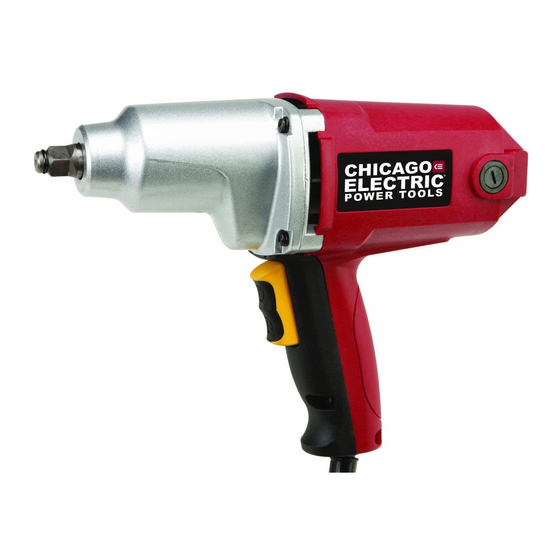
Summary of Contents for Chicago Electric 68099
-
Page 2: Table Of Contents
Table of Contents Safety ............2 Maintenance ..........10 Specifications ..........8 Parts List and Diagram ......12 Setup ............8 Warranty ............ 15 Operation ............ 9 WARNING SyMBOLS AND DEFINITIONS This is the safety alert symbol. It is used to alert you to potential personal injury hazards. -
Page 3: Electrical Safety
Electrical safety 1. power tool plugs must match the outlet. 4. Do not abuse the cord. Never use the cord Never modify the plug in any way. for carrying, pulling or unplugging the Do not use any adapter plugs with grounded power tool. -
Page 4: Impact Wrench Safety Warnings
power tool use and care 1. Do not force the power tool. Use the 4. Store idle power tools out of the reach of correct power tool for your application. children and do not allow persons unfamiliar The correct power tool will do the job better and with the power tool or these instructions safer at the rate for which it was designed. -
Page 5: Vibration Safety
Vibration Safety This tool vibrates during use. 2. Do not smoke during use. Nicotine reduces Repeated or long-term exposure to vibration may the blood supply to the hands and fingers, cause temporary or permanent physical injury, increasing the risk of vibration-related injury. particularly to the hands, arms and shoulders. - Page 6 Grounding TO pREVENT ELECTRIC SHOCK AND DEATH FROM INCORRECT GROUNDING WIRE CONNECTION: Check with a qualified electrician if you are in doubt as to whether the outlet is properly grounded. Do not modify the power cord plug provided with the tool. Never remove the grounding prong from the plug.
-
Page 7: Extension Cords
Extension Cords 1. Grounded tools require a three wire Grounded tools require a three wire Grounded extension cord. 7. Make sure the extension cord is properly wired Double Insulated tools can use either Double Insulated tools can use either Double Insulated and in good electrical condition. -
Page 8: Specifications
Specifications Electrical Rating 120V~ / 60Hz / 7A 2100 RPM Motor No Load Speed 2500 BPM Maximum Torque 230 ft. lbs. Drive Size 1/2" E194601 Setup - Before Use: Read the ENTIRE IMpORTANT SAFETy INFORMATION y INFORMATION section at the beginning of this manual including all text under subheadings therein before set up or use of this product. -
Page 9: General Operating Instructions
Operating Instructions Read the ENTIRE IMpORTANT SAFETy INFORMATION y INFORMATION section at the beginning of this manual including all text under subheadings therein before set up or use of this product. Workpiece and Work Area Set Up 1. Designate a work area that is clean and well- 3. -
Page 10: Operation
Maintenance and Servicing procedures not specifically explained in this manual must be performed only by a qualified technician. TO pREVENT SERIOUS INJURy REVENT SERIOUS INJURy REVENT SERIOUS INJUR FROM ACCIDENTAL y FROM ACCIDENTAL OpERATION: Release the Trigger and unplug the tool from its electrical outlet before performing any procedure in this section. -
Page 11: Troubleshooting
Troubleshooting problem possible Causes Likely Solutions Tool will not start. 1. Cord not connected. 1. Check that cord is plugged in. 2. No power at outlet. 2. Check power at outlet. If outlet is unpowered, turn off tool and check circuit breaker. If breaker is tripped, make sure circuit is right capacity for tool and circuit has no other loads. -
Page 12: Parts List And Diagram
parts List and Diagram pLEASE READ THE FOLLOWING CAREFULLy LEASE READ THE FOLLOWING CAREFULLy LEASE READ THE FOLLOWING CAREFULL THE MANUFACTURER AND/OR DISTRIBUTOR HAS PROVIDED THE PARTS LIST AND ASSEMBLY DIAGRAM IN THIS MANUAL AS A REFERENCE TOOL ONLY. NEITHER THE MANUFACTURER OR DISTRIBUTOR MAKES ANY REPRESENTATION OR WARRANTY OF ANY KIND TO THE BUYER THAT HE OR SHE IS QUALIFIED TO MAKE ANY REPAIRS TO THE PRODUCT, OR THAT HE OR SHE IS QUALIFIED TO REPLACE ANY PARTS OF THE PRODUCT. -
Page 13: Assembly Diagram
Assembly Diagram 9 10 11 Item 68099 For technical questions, please call 1-800-444-3353. Page 13... - Page 14 Record product’s Serial Number Here: Note: If product has no serial number, record month and year of purchase instead. If product has no serial number, record month and year of purchase instead. Note: Some parts are listed and shown for illustration purposes only, Some parts are listed and shown for illustration purposes only, and are not available individually as replacement parts.
-
Page 15: Warranty
Limited 90 Day Warranty Harbor Freight Tools Co. makes every effort to assure that its products meet high quality and durability standards, and warrants to the original purchaser that this product is free from defects in materials and workmanship for the period of 90 days from the date of purchase. - Page 16 3491 Mission Oaks Blvd. • PO Box 6009 • Camarillo, CA 93011 • (800) 444-3353...
Need help?
Do you have a question about the 68099 and is the answer not in the manual?
Questions and answers
Can I get a new trigger for this unit?
@Barry Garber
The trigger fell out, need a new trigger
The manual states that all repairs and parts replacements should be done by certified and licensed technicians. For technical questions or to inquire about replacement parts, you can call 1-800-444-3353.
This answer is automatically generated