Table of Contents
Advertisement
Available languages
Available languages
GARAGE DOOR OPENER
Model 1280LMC-R
1/2 HP
For Residential Use Only
Owner's Manual
I
Please read this manual and the enclosed safety materials carefully!
I
Fasten the manual near the garage door after installation.
The door WILL NOT CLOSE unless the Protector System
I
properly aligned.
I
Periodic checks of the opener are required to ensure safe operation.
I
The model number label is located under the light lens on the left side
panel of your opener.
is connected and
®
®
Advertisement
Chapters
Table of Contents

Related Manuals for Chamberlain 1280LMC-R 1/2 HP


Summary of Contents for Chamberlain 1280LMC-R 1/2 HP
- Page 1 ® GARAGE DOOR OPENER Model 1280LMC-R 1/2 HP For Residential Use Only Owner’s Manual Please read this manual and the enclosed safety materials carefully! Fasten the manual near the garage door after installation. The door WILL NOT CLOSE unless the Protector System is connected and ®...
-
Page 2: Table Of Contents
TABLE OF CONTENTS Introduction Pages 2-5 Adjustment Pages 24-26 Safety symbol and signal word review......2 Adjust the travel limits ..........24 Preparing your garage door ........3 Adjust the force ............25 Tools needed ...............3 Test the safety reversal system.........26 Planning ..............4 Test the Protector System ®... -
Page 3: Preparing Your Garage Door
Preparing your garage door WARNING Before you begin: To prevent possible SERIOUS INJURY OR DEATH: • Disable locks. • ALWAYS call a trained door systems technician if CAUTION • Remove any ropes connected to garage door. garage door binds, sticks, or is out of balance. An unbalanced garage door may not reverse when •... -
Page 4: Planning
Planning Identify the type and height of your garage door. Survey your garage area to see if any of the conditions below apply to your installation. Additional materials may be required. You may find it helpful to refer back to this page and the accompanying illustrations as you proceed with the installation of your opener. -
Page 5: Carton Inventory
Carton Inventory Your garage door opener is packaged in two cartons purchased. If anything is missing, carefully check the which contain the motor unit and all parts illustrated packing material. Parts may be stuck in the foam. below. Accessories will depend on the model Hardware for installation is also listed below. -
Page 6: Assembly
WARNING CAUTION ASSEMBLY STEP 1 Attach the T-Rail to the Motor Unit To avoid serious damage to opener, ONLY use screws mounted in top of motor unit. To avoid installation difficulties, do not run the garage door opener until instructed to do so. Washered Screw •... -
Page 7: Attach The Belt Cap Retainer
WARNING ASSEMBLY STEP 3 Attach the Belt Cap Retainer To avoid possible SERIOUS INJURY to fingers from moving garage door opener: CAUTION • Position the belt cap retainer over the motor unit • ALWAYS keep hand clear of sprocket while operating sprocket so the two holes in cap align with the two opener. -
Page 8: Determine The Header Bracket Location
INSTALLATION STEP 1 Determine the Header Bracket Finished Vertical Ceiling Location Centerline Header Structural Wall Supports WARNING WARNING To prevent possible SERIOUS INJURY or DEATH: • Header bracket MUST be RIGIDLY fastened to CAUTION WARNING structural support on header wall or ceiling, otherwise garage door might not reverse when required. - Page 9 ONE-PIECE DOOR WITHOUT TRACK Unfinished 1. Close the door and mark the inside vertical Ceiling centerline of your garage door. Extend the line Structural onto the header wall above door, as shown. Supports Header Wall Vertical If headroom clearance is minimal, you can install Centerline the header bracket on the ceiling.
-
Page 10: Install The Header Bracket
INSTALLATION STEP 2 Install the Header Bracket Wall Mounting Holes You can attach the header bracket either to the wall above the garage door, or to the ceiling. Follow the CEILING MOUNT ONLY The nail hole is for instructions which will work best for your particular positioning only. -
Page 11: Attach The T-Rail To The Header Bracket
INSTALLATION STEP 3 Attach the T-Rail to the Header Bracket • Position the opener on the garage floor below the header bracket. Use packing material as a protective base. NOTE: If the door spring is in the way you’ll need help. Have someone hold the opener securely on a temporary support to allow Header Wall the rail to clear the spring. -
Page 12: Position The Opener
WARNING CAUTION INSTALLATION STEP 4 Position the Opener To prevent damage to garage door, rest garage door opener rail on 2x4 placed on top section of door. Follow instructions which apply to your door type as illustrated. SECTIONAL DOOR OR ONE-PIECE DOOR WITH TRACK A 2x4 laid flat is convenient for setting an ideal door- to-rail distance. -
Page 13: Hang The Opener
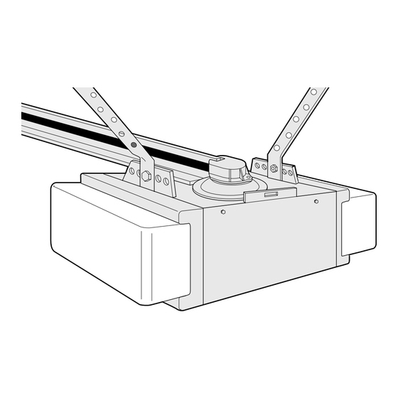
WARNING INSTALLATION STEP 5 Hang the Opener To avoid possible SERIOUS INJURY from a falling garage door opener, fasten it SECURELY to structural CAUTION Two representative installations are shown. Yours supports of the garage. Concrete anchors MUST be used may be different. Hanging brackets should be angled if installing any brackets into masonry. -
Page 14: Install The Door Control
WARNING WARNING CAUTION INSTALLATION STEP 6 WARNING Install the Door Control To prevent possible serious injury or death from electrocution: Locate door control within sight of the door at a • Be sure power is not connected before installing door minimum height of 5 feet where small children control. -
Page 15: Install The Lights And Lenses
INSTALLATION STEP 7 Lens Install the Lights and Lenses Lens Guide 75 Watt Maximum • Install a 75 watt maximum light bulb in each Light Bulb socket. The lights will turn ON and remain lit for approximately 4-1/2 minutes when power is connected. -
Page 16: Electrical Requirements
WARNING WARNING INSTALLATION STEP 9 Electrical Requirements To prevent possible SERIOUS INJURY or DEATH from electrocution or fire: CAUTION WARNING To avoid installation difficulties, do not run the • Be sure power is not connected to the opener, and opener at this time. disconnect power to circuit BEFORE removing cover to To reduce the risk of electric shock, your garage door establish permanent wiring connection. -
Page 17: Install The Protector System
WARNING INSTALLATION STEP 10 Install The Protector System ® • Be sure power is not connected to the garage door opener BEFORE installing the safety reversing sensor. CAUTION The safety reversing sensor must be connected • To prevent SERIOUS INJURY or DEATH from a closing and aligned correctly before the garage door garage door: opener will move in the down direction. - Page 18 INSTALLING THE BRACKETS Figure 1 Be sure power to the opener is disconnected. DOOR TRACK MOUNT (RIGHT SIDE) Install and align the brackets so the sensors will face each other across the garage door, with the beam no Door higher than 6" above the floor. They may be installed Track in one of three ways, as follows.
-
Page 19: Mounting And Wiring The Safety Sensors
MOUNTING AND WIRING THE SAFETY SENSORS Figure 4 • Slide a 1/4"-20x1/2" carriage bolt head into the slot Wing nut on each sensor. Use wing nuts to fasten sensors to brackets, with lenses pointing toward each other across the door. Be sure the lens is not obstructed by a bracket extension. -
Page 20: Fasten The Door Bracket
WARNING CAUTION INSTALLATION STEP 11 Fasten the Door Bracket To prevent damage to garage door, reinforce inside of door with angle iron both vertically and horizontally. Follow instructions which apply to your door type as illustrated below or on the following page. A horizontal reinforcement brace should be long Header enough to be secured to two or three vertical... - Page 21 ONE-PIECE DOORS Please read and comply with the warnings and reinforcement instructions on the previous page. They apply to one-piece doors also. • Center the door bracket on the top of the door, in line with the header bracket as shown. Mark either the left and right, or the top and bottom holes.
-
Page 22: Connect Door Arm To Trolley
Inner Trolley INSTALLATION STEP 12 Connect Door Arm to Trolley Outer Trolley Follow instructions which apply to your door type as illustrated below and on the following page. Clevis Pin 5/16"x1" SECTIONAL DOORS ONLY Ring Fastener • Make sure garage door is fully closed. Pull the emergency release handle to disconnect the outer trolley from the inner trolley. -
Page 23: Connect The Door Arm To The Trolley
ALL ONE-PIECE DOORS 1. Assemble the door arm: • Fasten the straight and curved door arm sections together to the longest possible length (with a 2 Door Bracket Ring or 3 hole overlap). Fastener Nuts • With the door closed, connect the straight door Lock 5/16"-18 arm section to the door bracket with the... -
Page 24: Adjustment
WARNING ADJUSTMENT STEP 1 Adjust the UP and DOWN Travel Without a properly installed safety reversal system, Limits persons (particularly small children) could be CAUTION SERIOUSLY INJURED or KILLED by a closing garage Limit adjustment settings regulate the points at which door. -
Page 25: Adjust The Force
WARNING ADJUSTMENT STEP 2 Adjust the Force Without a properly installed safety reversal system, persons (particularly small children) could be CAUTION Force adjustment controls are located on the right SERIOUSLY INJURED or KILLED by a closing garage panel of the motor unit. Force adjustment settings door. -
Page 26: Test The Safety Reversal System
WARNING ADJUSTMENT STEP 3 Test the Safety Reversal System Without a properly installed safety reversal system, persons (particularly small children) could be CAUTION SERIOUSLY INJURED or KILLED by a closing garage TEST door. • With the door fully open, place a one-inch board •... -
Page 27: Operation
OPERATION IMPORTANT SAFETY INSTRUCTIONS WARNING To reduce the risk of severe injury or death: CAUTION 1. READ AND FOLLOW ALL WARNINGS AND 8. If one control (force or travel limits) is adjusted, the INSTRUCTIONS. other control may also need adjustment. 2. -
Page 28: Using The Wall-Mounted Door Control
Using the Wall-Mounted B) To operate one door using all three buttons on the Door Control Open hand-held remote: Close You may program the remote to Stop THE MULTI-FUNCTION DOOR CONTROL open the door with the large button, close it with the Press the push bar to open or Push middle button, and stop the door’s movement with... -
Page 29: Having A Problem
Care of Your Opener Having a Problem? 1. The opener doesn't operate from either the LIMIT AND FORCE ADJUSTMENTS: Door Control or the remote control: Weather conditions may cause • Does the opener have electric power? Plug a lamp some minor changes in door into the outlet. - Page 30 Having a Problem? (Continued) 11. The door reverses for no apparent reason and opener lights blink for 5 seconds after 6. The garage door opens and closes by itself: reversing: • Be sure that all remote control push buttons are •...
-
Page 31: Programming
PROGRAMMING Your garage door opener has already been programmed at the factory to operate with your hand-held remote control. The door will open and close when you press the large push button. Below are instructions for programming your opener to operate with additional Security✚ remote controls. To Add an Additional Hand-held Remote Control USING THE “LEARN”... -
Page 32: To Add Or Change A Keyless Entry Pin
To Add or Change a Keyless Entry PIN Note: Your new Keyless Entry must be programmed to operate your garage door opener. USING THE “LEARN” BUTTON USING THE MULTI-FUNCTION DOOR CONTROL 1. Press and release the “learn” NOTE: This method requires two people if the Keyless button on motor unit. -
Page 33: Repair Parts Pages
REPAIR PARTS Rail Assembly Parts PART DESCRIPTION 4A1008 Master link kit 41A3588-1 Belt pulley bracket 41B3869-1 Complete trolley assembly 109B33 Trolley clip 183B99 One-piece T-rail 41A3589-12 Full belt assembly 41B4103 Tensioner assembly 83A11-2 Rail grease Installation Parts KEY PART DESCRIPTION 41A5273-1 Multi-function door control panel 41A5056-3... -
Page 34: Motor Unit Assembly Parts
Motor Unit Assembly Parts 18 19 (Down) LIMIT SWITCH ASSY. Brown Contact Wire Grey Wire Drive Gear Center Limit (Up) Yellow Contact Contact Wire PART PART DESCRIPTION DESCRIPTION 41A4371 Belt cap retainer 41D3150 Terminal block w/screws 41A4885-2 Gear and sprocket assy., 41C4842 Universal replacement motor &... -
Page 35: Accessories
ACCESSORIES 1702LMC Outside Quick Release: Plug-in Light Control: 982LMC Required for a garage with NO Enables homeowner to turn on a access door. Enables homeowner to lamp, television or other appliance open garage door manually from from car, bedside, or anywhere in the outside by disengaging trolley. -
Page 36: Warranty
LIFTMASTER GARAGE DOOR OPENER FIVE-YEAR LIMITED WARRANTY The Chamberlain Group, Inc. (“Seller”) warrants to the first retail purchaser of this product, for the residence in which this product is originally installed, that it will be free from any defect in materials and/or workmanship for a period of five years from the date of purchase. - Page 37 ® Ouvre-porte de garage Modèle 1280LMC-R 1/2HP Pour résidences seulement Manual d'Instructions Lire attentivement ce manuel ainsi que les consignes de sécurité! Après la pose, accrocher ce manuel près de la portedu garage pour s'y reporter ultérieurement. La porte NE SE FERMERA PAS si le Système PROTECTOR n'est pas branchè et réglé...
-
Page 38: Introduction
TABLE DES MATIÈRES Introduction Pages 2-5 Réglages Pages 24-26 Revue des symboles de sécurité Réglage des courses et des mots de signalement Réglage de la force Préparation de votre porte de garage Contrôle du système d'inversion de sécurité Outils nécessaires Essai du Système Protector ®... -
Page 39: Préparation De Votre Porte De Garage
Préparation de votre porte AVERTISSEMENT AVERTISSEMENT de garage Pour prévenir d’éventuelles LÉSIONS GRAVES OU LA Avant de commencer: MORT: WARNING ATTENTION • Inactiver les serrures. • TOUJOURS appeler un technicien formé en systèmes de • Retirer toute corde raccordée à la porte de garage. porte si la porte de garage force ou est déséquilibrée. -
Page 40: Planification
Planification Identifier le type et la hauteur de votre porte de garage. Examiner la région du garage pour noter si l’une des conditions ci-après s’applique à votre installation. Des matériaux supplémentaires peuvent être nécessaires. Il vous sera peut-être utile de vous reporter à cette page et aux illustrations qui l’accompagnent en procédant à la pose de l’ouvre-porte. -
Page 41: Inventaire Des Boîtes D'emballage
Inventaire des boîtes d’emballage Votre ouvre-porte de garage est emballé dans deux soigneusement le matériel d’emballage. Les pièces boîtes qui contiennent le moteur et toutes les pièces peuvent être coincées dans la mousse. Les ferrures illustrées ci-après. Les accessoires dépendront du de montage sont également indiquées ci-après. -
Page 42: Fixation Du Rail En T Au Moteur
AVERTISSEMENT ATTENTION MONTAGE - 1RE OPÉRATION Fixation du rail en T au moteur Pour éviter des domages sérieux à l’ouvre-porte, utiliser UNIQUEMENT les vis montées sur le dessus du moteur. Pour éviter les problèmes d’installation, ne pas faire fonctionner l’ouvre-porte de garage avant d’avoir reçu l’instruction de le faire. -
Page 43: Attachement Du Capuchon De Maintien De La Courroie
AVERTISSEMENT AVERTISSEMENT MONTAGE - 3E OPÉRATION Attachement du capuchon de Pour éviter d’éventuelles LÉSIONS GRAVES aux doigts par maintien de la courroie• suite du mouvement de l’ouvre-porte : ATTENTION • TOUJOURS garder la main à l’écart du pignon en faisant •... -
Page 44: Déterminer L'emplacement Du Support De Linteau
POSE - 1 OPÉRATION Déterminer l'emplacement du support de linteau Plafond fini vertical Linteau AVERTISSEMENT AVERTISSEMENT Solives Pour prévenir d’éventuelles LÉSIONS GRAVES ou la MORT : • Le support de linteau DOIT être fixé DE MANIÈRE RIGIDE à la ATTENTION AVERTISSEMENT solive sur le linteau ou le plafond, sinon la porte de garage pourrait ne pas remonter au besoin. - Page 45 PORTE RIGIDE SANS GUIDES Plafond 1.La porte étant fermée, repérer et tracer l'axe vertical non fini de la porte du garage et prolonger cette ligne sur le Solives mur, au-dessus de la porte comme il est illustré. Linteau Si la hauteur au-dessus du plafond n'est pas vertical suffisante, on pourra poser le support de linteau sur le plafond.
-
Page 46: Pose Du Support De Linteau
POSE - 2e OPÉRATION Pose du support de linteau Trous de fixation au mur Le support de linteau peut être fixé soit sur le mur Le trou du clou n'est prévu que au-dessus de la porte, soit sur le plafond. Suivre les CEILING MOUNT ONLY pour le positionnement seulement. -
Page 47: Fixation Du Rail Sur Le Support De Linteau
POSE - 3 OPÉRATION Fixation du rail sur le support de linteau • Positionner l'ouvre-porte de garage sur le plancher, juste sous le support de linteau. Utiliser une des boîtes d'emballage pour le protéger. REMARQUE : Si le ressort de la porte gêne, il faudra demander de l'aide. -
Page 48: Positionnement De L'ouvre-Porte
AVERTISSEMENT ATTENTION POSE - 4 OPÉRATION Positionnement de l'ouvre-porte Pour prévenir les dommages à la porte de garage, faire reposer le rail de l’ouvre-porte de garage sur un 2x4 placé sur la Suivre les instructions qui se rapportent à la porte du section supérieure de la porte. -
Page 49: Accrochage De L'ouvre-Porte
AVERTISSEMENT POSE - 5 OPÉRATION Accrochage de l'ouvre-porte Pour éviter d’éventuelles BLESSURES GRAVES par suite de la chute d’un ouvre-porte de garage, fixer l’ouvre-porte ATTENTION Les illustrations représentent deux poses type. La pose SOLIDEMENT aux solives du garage. On DOIT utiliser des peut toutefois être différente. -
Page 50: Pose De La Commande De Porte
AVERTISSEMENT AVERTISSEMENT ATTENTION AVERTISSEMENT POSE - 6 OPÉRATION Pose de la commande de porte Pour prévenir d’éventuelles lésions graves ou la mort par suite d’électrocution : Placez le contrôle de porte en vue de la porte à une • S’assurer qu’il n’y a pas de courant avant de poser la hauteur minimum de 5 pieds hors d'atteinte des enfants en commande de porte. -
Page 51: Pose De La Corde Et De La Poignée De Déclenchement D'urgence
POSE - 7 OPÉRATION Pose des ampoules et des Guides du diffuseur diffuseurs Ampoules de 75 watts maximum • Visser une ampoule de 75 watts maximum dans chaque douille. La lumière s’allumera et restera Patte du allumée pendant environ 4-1/2 minutes aussitôt que diffuseur le courant sera établi. -
Page 52: Exigences Électriques
AVERTISSEMENT AVERTISSEMENT POSE - 9 OPÉRATION Exigences électriques Pour prévenir d’éventuelles LÉSIONS GRAVES ou la MORT par suite d’électrocution ou d’un incendie : ATTENTION AVERTISSEMENT Pour éviter de rencontrer des difficultés pendant la • S’assurer que l’ouvre-porte est hors tension et couper le pose, ne pas faire fonctionner l'ouvre-porte pour courant au circuit AVANT de retirer le couvercle pour procéder à... -
Page 53: Pose Du Système Protector
AVERTISSEMENT POSE - 10 OPÉRATION Pose du Système Protector ® • S’assurer que l’ouvre-porte de garage est hors tension AVANT de poser le détecteur inverseur de sécurité. ATTENTION Les détecteurs inverseurs de sécurité doivent être • Pour prévenir des LÉSIONS GRAVES ou la MORT par suite bien branchés et bien alignés avant que l'ouvre- d’une porte de garage qui se ferme : porte de garage puisse fermer la porte. - Page 54 POSE DES SUPPORTS Figure 1 S’assurer que l’ouvre-porte est hors tension. MONTAGE SUR GUIDES DE PORTE (côté droit) Poser et aligner les supports de manière à ce que les détecteurs se fassent face l’un l’autre à travers la porte Guide du garage, le faisceau n’étant pas à...
- Page 55 MONTAGE ET CÂBLAGE DES Figure 4 DÉTECTEURS INVERSEURS Écrou à oreilles • Faire glisser un boulon à tête bombée et collet carré de 1/4 po-20x1/2 po dans la fente de chaque capteur. Utiliser des écrous à oreilles pour fixer les détecteurs aux supports, avec les diffuseurs dirigés l’un vers l’autre à...
-
Page 56: Fixation Du Support De La Porte
AVERTISSEMENT ATTENTION POSE - 11 OPÉRATION Fixation du support de porte Pour prévenir les dommages à la porte de garage, renforcer l’intérieur de la porte par une ferrure angulaire, tant Suivre les instructions qui correspondent au type de verticalement qu’horizontalement. porte, comme il est illustré... - Page 57 PORTES RIGIDES Prière de lire et de suivre les avertissements et les instructions de renforcements à la page précédente. Ils s’appliquent également aux portes rigides. • Centrer le support de porte sur le dessus de la porte, en l'alignant avec le support de linteau, comme il est illustré.
-
Page 58: Fixation De La Biellette De La Porte Au Chariot
Chariot intérieur POSE - 12E OPÉRATION Fixation de la biellette au chariot Chariot extérieur Suivre uniquement les instructions se reportant au type de porte, comme il est illustré ci-dessous et à la Axe de chape de page suivante. 5/16 po x1 po Anneau d'arrêt PORTE ARTICULÉE SEULEMENT •... - Page 59 POUR TOUTES LES PORTES RIGIDES Support de la porte Anneau 1. Assemblage des biellettes : d'arrêt Écrous de • Assembler les biellettes droite et courbée à leur 5/16 po-18 Rondelle-freins plus grande longueur (2 ou 3 trous se de 5/16 po chevauchant).
-
Page 60: Réglage Des Courses
AVERTISSEMENT RÉGLAGES - 1 OPÉRATION Réglage des courses d’ouverture et Sans un système d’inversion de sécurité bien installé, des de fermeture personnes (plus particulièrement les petits enfants) pourraient ATTENTION être GRIÈVEMENT BLESSÉES ou TUÉES par une porte de Le réglage de ces courses fixe les points où la porte garage qui se referme. -
Page 61: Réglage De La Force
AVERTISSEMENT RÉGLAGES - 2 OPÉRATION Réglage de la force Sans un système d’inversion de sécurité bien installé, des personnes (plus particulièrement les petits enfants) pourraient ATTENTION Les commandes de réglage de la force sont situées être GRIÈVEMENT BLESSÉES ou TUÉES par une porte de sur le panneau côté... - Page 62 AVERTISSEMENT RÉGLAGES - 3 OPÉRATION Essai du système d’inversion de Sans un système d’inversion de sécurité bien installé, des sécurité personnes (plus particulièrement les petits enfants) pourraient ATTENTION être GRIÈVEMENT BLESSÉES ou TUÉES par une porte de garage qui se referme. CONTRÔLE : •...
-
Page 63: Utilisation De Votre Ouvre-Porte De Garage
FONCTIONNEMENT IMPORTANTES CONSIGNES DE SÉCURITÉ AVERTISSEMENT Pour réduire le risque de blessures graves ou de mort : ATTENTION 1. LIRE ET SUIVRE TOUS LES AVERTISSEMENTS ET INSTRUCTIONS. 8. Après avoir réglé une commande (force ou course), il peut être nécessaire de régler l’autre commande. 2. -
Page 64: Utilisation De La Commande De Porte
Utilisation de la commande de B) Pour actionner une porte en utilisant les trois boutons de la télécommande à main porte à montage mural (ouverture/fermeture/arrêt) : On peut programmer la Ouverture PANNEAU COMMANDE DE PORTE Fermeture télécommande de manière à ouvrir Arrêt Appuyer sur la barre pour la porte avec le gros bouton, à... -
Page 65: Entretien De Votre Ouvre-Porte De Garage
Entretien de l’ouvre-porte de garage Défauts de fonctionnement RÉGLAGES DE COURSE ET DE FORCE : 1. L’ouvre-porte ne fonctionne pas à l’aide de la commande de porte ni de la télécommande : Les conditions climatiques risquent •. Le courant électrique parvient-il à l’ouvre-porte? Brancher de causer de petites modifications dans le fonctionnement de la porte une lampe dans la prise de courant. - Page 66 Défauts de fonctionnement (suite) 11. Le mouvement de la porte s´inverse sans raison apparente et les témoins de l´ouvre-porte 6. La porte s’ouvre et se ferme toute seule: clignotent pendant 5 secondes après l´inversion : • Vérifier les détecteurs inverseurs de sécurité. •...
-
Page 67: Pour Ajouter Une Télécommande À Main
PROGRAMMATION Votre ouvre-porte de garage a été programmé en usine de manière à fonctionner avec votre télécommande à main. La porte s’ouvrira et se fermera lorsque vous appuierez sur le gros bouton-poussoir. Vous trouverez ci-après des instructions pour programmer votre ouvre-porte en vue du fonctionnement avec d’autres télécommandes Security✚. -
Page 68: Pour Ajouter Ou Modifier Un Nip D'entrée Sans Clé
Pour ajouter ou modifier un NIP d’entrée sans clé Remarque : Votre nouvelle entrée sans clé doit être programmée de manière à faire fonctionner votre ouvre-porte de garage. UTILISATION DU BOUTON « LEARN » UTILISATION DE LA COMMANDE DE PORTE MULTIFONCTION 1. -
Page 69: Pièces D'assemblage Des Rails
PIÈCES DE RECHANGE Pièces d’assemblage des rails RÉF. PIÉCE DÉSIGNATION 4A1008 Maillon de raccord 41A3588-1 Support de poulie de courroie 41B3869-1 Chariot complet 109B33 Pince de chariot 183B99 Rail rigide 41A3589-12 Ensemble courroie complet 41B4103 Ensemble tendeur 83A11-2 Graisse à rail Pièces pour la pose RÉF. - Page 70 Pièces du bloc-moteur 18 19 Contact de INTERRUPTEUR DE FIN (fermeture) DE COURSE brun gris Pignon menant Contact de fin Contact de course central (d'ouverture) jaune RÉF. N° DE RÉF. N° DE PIÈCE DÉSIGNATION PIÈCE DÉSIGNATION 41A4371 Capuchon de maintien 4A1344 Douille d’ampoule de la courroie...
-
Page 71: Accessoires
ACCESSOIRES Modèle 982LMC Commande-récepteur d’éclairage Modèle 1702LMC Détachement rapide d'extérieur: Nécessaire pour un garage SANS à brancher : porte d'accès. Permet au Permet d’allumer une lampe, le propriétaire d'ouvrir la porte de téléviseur ou tout autre appareil à l’aide garage manuellement à partir de de la télécommande, sans sortir de la l'extérieur en déconnectant le voiture. -
Page 72: Garantie
Le produit doit être utilisé en stricte conformité avec les instructions d’installation, d’utilisation et d’entretien données par Chamberlain. Le fonctionnement approprié de ce produit dépend de votre observance des instructions du manuel concernant l’installation, l’utilisation, l’entretien et les essais.
Need help?
Do you have a question about the 1280LMC-R 1/2 HP and is the answer not in the manual?
Questions and answers