Table of Contents
Advertisement
48XL---A
Infinity
®
15 SEER Single---Packaged Air Conditioner and
Gas Furnace System with Puron
Single Phase
2---5 Nominal Tons (Sizes 24---60)
CAUTION
!
EQUIPMENT OPERATION HAZARD
Failure to follow this caution may result in improper unit
operation.
OAT sensor must be field installed. See Accessory
Installation for more details.
CAUTION
!
EQUIPMENT OPERATION HAZARD
Failure to follow this caution may result in improper unit
operation.
This InfinityR unit is designed for use with an Infinity User
Interface.
NOTE:
Read the entire instruction manual before starting the
installation.
TABLE OF CONTENTS
. . . . . . . . . . . . . . . . . . . . . . . . . . . . . . . . . . .
. . . . . . . . . . . . . . . . . . . . . . . . . . . . . . . . . .
. . . . . . . . . . . . . . . . . . . . . . . . . . . . . . . . . . . .
. . . . . . . . . . . . . . . . . . . . . . . . . . . . . . . . .
. . . . . . . . . . . . . . . . . . . . . . . . . . . . . . .
. . . . . . . . . . . . . . . . . . . . . . . . . . . . . . . . . . . . . .
. . . . . . . . . . . . . . . . . . . . . . . . . . . . . . . . . . . . .
. . . . . . . . . . . . . . . . . . . . . . . . . . . . . . . . .
. . . . . . . . . . . . . . . . . . . . . . . . . . . . . . . . .
. . . . . . . . . . . . . . . . . . . . . . . . . . . . . . . . . . . . . .
. . . . . . . . . . . . . . . . . . . . . . . . . . . .
. . . . . . . . . . . . . . . . . . . . . . . . . . . . . . . . . .
. . . . . . . . . . . . . . . . . . . . . . . . . . . . . . . . .
. . . . . . . . . . . . . . . . . . . . . . . . . . . .
. . . . . . . . . . . . . . . . . . . . . . . . . . . . . . . . . . .
. . . . . . . . . . . . . . . . . . . . . . . . . . . . . . . . . . . . .
. . . . . . . . . . . . . . . . . . . . . . . . . . . . .
. . . . . . . . . . . . . . . . . . . . . . . . . . . . . .
®
Installation Instructions
. . . . . . . . . . . . . . . . . . . . . . . . .
. . . . . . . . . . . . . . . . .
. . . . . . . . . . . . . . . . . . . . . . . . . . .
. . .
. . . . . . . . . . . . . . . . . . . . .
. . . . . . . . . . . . . . . . . . . . . . . .
. . . . . . . . . . . . . . . . . . . . . . . .
. . . . . . . . . . . . . . . . . . . . .
. . . . . . . . . . .
. . . . . . . . . . . . . . . . . . . . .
. . . . . . . . . . . . . .
. . . . . . . . . . . . . . . . . . .
. . . . . . . . . . . . . . . . . . . . . . . . .
(R---410A) Refrigerant
PAGE
2
2
2- -12
2
2
2
. . . . . . . . . . . . . . . . . . . . . . . . . . . . . . . . . . . . . . . .
2
2
3
3
3
3
9
9
10
10
11
11
12
12
13
13
13
13
13
16
16- -29
16
23
28
28
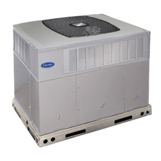
1
Fig. 1 - - Unit 48XL- -A
. . . . . . . . . . . . . . . . . . . . . . . . . . . . . .
. . . . . . . . . . . . . . . . . . . . . . . . . . . . . . . . . . . . .
. . . . . . . . . . . . . . . . . . . . . . . . . . . . .
. . . . . . . . . . . . . . . . . . . .
. . . . . . . . . . . . . . . . . . . . . . . . . . . . . . . .
. . . . . . . . . . . . . . . . . . . . . . . . . . . . . .
. . . . . . . . . . . . . . . . . . . . . . . . . . . . . . . . . . .
. . . . . . . . . . . . . . . . . . . . . . . . . . . . . . . . . . . . .
. . . . . . . . . . . . . . . . . . . . . . . . . . . . . . . . . . .
. . . . . . . . . . . . . . . . . . . . . . . . . . . . . . . . . . . .
. . . . . . . . . . . . . . . . . . . . . . . . . . . .
. . . . . . . . . . . . . . . . . . . . . . . . . . . . . . . . . . . . .
. . . . . . . . . . . . . . . . . . . . . . .
. . . . . . . . . . . . . . . . . . . . . . . . . . . . . . . . .
. . . . . . . . . . . . . . . . . . . . . . . . . . . . . . . . . . .
. . . . . . . . . . . . . . . . . . . . . . . . . . . . . . . . .
. . . . . . . . . . . . . . . . . . . . . . . . . . . .
. . . . . . . . . . . . . . . . . . . . . . . . . . . .
®
. . . . . . . . . . . . . . . . . . . . . . . . . . . . . . . .
. . . . . . . . . . . . . . . . . . . . . . . . . . . . . . . . . . . .
. . . . . . . . . . . . . . . . . . . . . . . . . . . . . . . . .
. . . . . . . . . . . . . . . . . . . . . . . . . .
. . . . . . . . . . . . . . .
. . . . . . . . . . . . . . . . . . . . . . . . . . . . . .
. . . . . . . . . . . . . . . . . . . . . . . . . . . . . . . . . . .
. . . . . . . . . . . . . . . . . . . . . . . .
. . . . . . . . . . . . . . . . . . . . . . . . . . . .
A09032
. . . . . .
28
. . . . . . . . . . .
28
29
29
29
29
. .
29
31- -34
31
31
31
31
31
31
32
. . . . .
32
32
32
33
33
33
33
33
. . . . . . . .
33
33
33
33
. . . .
33
34
34
34
35
35
40
Advertisement
Table of Contents
Troubleshooting

Related Manuals for Carrier INFINITY 48XL-A


Summary of Contents for Carrier INFINITY 48XL-A
-
Page 1: Table Of Contents
48XL---A Infinity ® 15 SEER Single---Packaged Air Conditioner and Gas Furnace System with Puron (R---410A) Refrigerant ® Single Phase 2---5 Nominal Tons (Sizes 24---60) Installation Instructions CAUTION EQUIPMENT OPERATION HAZARD Failure to follow this caution may result in improper unit operation. -
Page 2: Safety Considerations
SAFETY CONSIDERATIONS units can be converted to downflow (vertical) discharge configurations for rooftop applications. Improper installation, adjustment, alteration, service maintenance, In gas heating mode, this unit is designed for a minimum or use can cause explosion, fire, electrical shock, or other continuous return- -air temperature of 55_F (13_C) db and a conditions which may cause death, personal injury, or property maximum continuous return- -air temperature of 80_F (27_C) db. -
Page 3: Slab Mount
Provide Clearances The required minimum service clearances are shown in Fig. 5 and 6. Adequate ventilation and outdoor air must be provided. The outdoor fan draws air through the outdoor coil and discharges it through the top fan grille. Be sure that the fan discharge does not recirculate to the outdoor coil. - Page 4 Dashed lines show cross support location for large basepan units. HVAC unit HVAC unit basepan base rails Sealing Gasket Roofcurb Anchor screw Wood nailer* Flashing field supplied Roofcurb* Insulation (field supplied) Roofing material field supplied Cant strip field supplied SMALL/COMMON CURB A09413 *Provided with roofcurb A09090...
- Page 5 A09521 Fig. 5 - - 48XL- -A24- -30 Unit Dimensions...
- Page 6 A09522 Fig. 6 - - 48XL- -A36- -60 Unit Dimensions...
- Page 7 Table 1 – Physical Data - - Unit 48XL- -A UNIT SIZE 24040 24060 30040 30060 36060 36090 42060 42090 NOMINAL COOLING CAPACITY (ton) 2--- 1/2 2--- 1/2 3--- 1/2 3--- 1/2 NOMINAL HEATING CAPACITY (Btu) 40,000 60,000 40,000 60,000 60,000 90,000 60,000...
- Page 8 Table 1—Physical Data (Con’t) - - Unit 48XL- -A UNIT SIZE 48090 48115 48130 60090 60115 60130 NOMINAL COOLING CAPACITY (ton) NOMINAL HEATING CAPACITY (Btu) 90,000 115,000 130,000 90,000 115,000 130,000 SHIPPING WEIGHT (lb) (kg) 2--- Stage Scroll COMPRESSORS Quantity REFRIGERANT: PURON (R--- 410A) 15.3 15.3...
-
Page 9: Rigging/Lifting Of Unit
CAUTION - NOTICE TO RIGGERS PRUDENCE - AVIS AUX MANIPULATEUR ACCESS PANELS MUST BE IN PLACE WHEN RIGGING. PANNEAUX D'ACCES DOIT ÊTRE EN PLACE POUR MANIPULATION. Use top skid as spreader bar. / Utiliser la palette du haut comme barre de répartition DUCTS MINIMUM HEIGHT: 36"... -
Page 10: Configuring Units For Downflow (Vertical) Discharge
2. Avoid abrupt duct size increases and reductions. Abrupt change in duct size adversely affects air performance. IMPORTANT: Use flexible connectors between ductwork and unit to prevent transmission of vibration. Use suitable gaskets to ensure weather tight and airtight seal. When electric heat is installed, use fireproof canvas (or similar heat resistant material) connector between ductwork and unit discharge connection. -
Page 11: Install Flue Hood
condensate connection to ensure proper drainage. Make sure that For natural gas applications, the gas pressure at unit gas connection the outlet of the trap is at least 1 in. (25 mm) lower than the must not be less than 4.0 IN. W.C. or greater than 13 IN. W.C. drain- -pan condensate connection to prevent the pan from while the unit is operating. -
Page 12: Install Electrical Connections
Table 2 – Maximum Gas Flow Capacity* LENGTH OF PIPE ft (m)† NOMINAL INTERNAL IRON PIPE DIAMETER SIZE (IN.) (IN.) (3.0) (6.1) (9.1) (12.1) (15.2) (18.3) (21.3) (24.4) (27.4) (30.5) (38.1) (45.7) (53.3) (61.0) .622 — — .824 1.049 1--- 1/4 1.380 1400 1--- 1/2... -
Page 13: Routing Power Leads Into Unit
ROUTING POWER LEADS INTO UNIT The OAT input is used to supply outdoor temperature data for system level functions and for temperature display on User Use only copper wire between disconnect and unit. The high Interface (UI). Using two wires of the field- -supplied thermostat voltage leads should be in a conduit until they enter the duct panel;... - Page 14 A09075 Fig. 11 - - Typical Installation GROUND SCREW (IN SPLICE BOX) GROUND LEAD SINGLE-PHASE CONNECTIONS TO DISCONNECT PER NEC NOTE: Use copper wire only. LEGEND NEC – National Electrical Code Field Wiring Splice Connections A06299 Fig. 12 - - Line Power Connections...
- Page 15 HP/AC BOARD FURNACE BOARD A09108 Fig. 13 - - Control Plate Infinity Furnace A06301 Fig. 14 - - Control Voltage Wiring Connections...
-
Page 16: Pre- -Start- -Up
PRE- -START- - UP joint union be loosened, and the supply line be allowed to purge until the odor of gas is detected. Never purge gas lines into a WARNING combustion chamber. Immediately upon detection of gas odor, retighten the union. Allow 5 minutes to elapse, then light unit. b. - Page 17 emergency heating or cooling operation using a common operate electric heaters while a fault condition exists. The control thermostat and the terminal strip connections on the two control communicates with the motor at least once every five seconds, boards (See Non- -Communicating Emergency Cooling/Heating even when the motor is idle.
- Page 18 A10217C Fig. 16 - - Connection Wiring Schematic- -48XL- -A Single Phase Gas Inputs 040, 060, 090 kBtu/hr...
- Page 19 A10217L Fig. 16 Cont. - - Ladder Wiring Schematic- -48XL- -A Single Phase Gas Inputs 040, 060, 090 kBtu/hr...
- Page 20 A10219C Fig. 17 - - Connection Wiring Schematic- -48XL- -A Single Phase Gas Inputs 115, 130 kBtu/hr...
- Page 21 A10219L Fig. 17 Cont. - - Ladder Wiring Schematic- -48XL- -A Single Phase Gas Inputs 115, 130 kBtu/hr...
- Page 22 UTILITY RELAY Liquid Line Solenoid UTILITY SIGNAL OPEN RELAY SUPPLIED BY UTILITY PROVIDER A05247 Fig. 18 - - 2- -Stage HP/AC Control Board STATUS CODE 21 - - GAS HEATING LOCKOUT shuts off. Check for loose blower wheel, restricted vent, excessive Control will NOT auto reset.
-
Page 23: Sequence Of Operation
open or shorted at any time after initial validation, Status Code 53 NOTE: When two- -stage unit is operating at low- -stage, system will be displayed at amber STATUS LED. vapor (suction) pressure will be higher than a standard single- -stage system or high- -stage operation. - Page 24 Table 3 – Air Delivery and Temperature Rise at Rated Heating Input Rated Heating Input (Btu/hr) Heating Rise Range Heating Rise Either Stage, °F ( Unit “Efficiency” “Comfort” High Stage Low Stage High Stage Low Stage High Stage Low Stage High Stage Low Stage 48XL( ---,N)A24040...
- Page 25 INFINITY CONTROLLED LOW AMBIENT COOLING period begins. NOTE: The unit always lights on high speed inducer and low stage gas valve operation. NOTE: When this unit is operating below 55_F (13°C) outdoor 3. Flame- -Proving: When the burner flame is proved at the temperature, provisions must be made for low ambient operation.
- Page 26 b. When the gas supply being used has a different heating WARNING value or specific gravity, refer to national and local codes, or contact your distributor to determine the required orifice size. CARBON MONOXIDE POISONING HAZARD 2. Adjust manifold pressure to obtain low stage input rate (See Failure to follow this warning could result in personal Fig.
- Page 27 a. 129 sec. to complete one revolution In this example, the nominal input rate for high stage is 90,000 Btu/hr, so the high stage manifold pressure is correctly set. b. 3600/129 = 27.9 If the measured high stage rate is too low, increase the manifold c.
-
Page 28: Check For Refrigerant Leaks
COMPONENT TEST BURNER FLAME The Infinity Furnace Board features a gas component test system to help diagnose a system problem in the case of a gas component failure. To initiate the component test procedure, ensure that there BURNER are no UI inputs to the control (the ABCD connector can be removed from the Infinity control board for this operation) and all time delays have expired. -
Page 29: Refrigerant Charge
Table 6 – Heating Inputs GAS SUPPLY PRESSURE (IN. W.C.) MANIFOLD PRESSURE (IN. W.C.) HEATING INPUT (BTU/HR)* NUMBER OF NUMBER OF Natural Natural ORIFICES ORIFICES High Stage Low Stage High Stage Low Stage 40,000 26,000 13.0 3.2∼ 3.8 1.4 ∼ 2.0 60,000 39,000 13.0... - Page 30 Infinity Furnace A06302 Fig. 22 - - Non- -Communicating Emergency Cooling/Heating Wiring Connections A09109 Fig. 23 - - Cooling Charging Table- -Subcooling...
-
Page 31: Maintenance
MAINTENANCE Air Filter IMPORTANT: Never operate the unit without a suitable air filter To ensure continuing high performance, and to minimize the in the return- -air duct system. Always replace the filter with the possibility of premature equipment failure, periodic maintenance must be performed on this equipment. -
Page 32: Inducer Pressure Switch
Outdoor Coil, Indoor Coil, and Condensate Drain Pan Inspect the condenser coil, evaporator coil, and condensate drain pan at least once each year. The coils are easily cleaned when dry; therefore, inspect and clean the coils either before or after each cooling season. Remove all obstructions, including weeds and shrubs, that interfere with the airflow through the condenser coil. -
Page 33: Refrigerant Circuit
Copeland Scroll Compressor (Puron Refrigerant) The compressor used in this product is specifically designed to operate with Puron (R- -410A) refrigerant and cannot be interchanged. The compressor is an electrical, as well as mechanical, device. Exercise extreme caution when working near compressors. Power should be shut off, if possible, for most troubleshooting techniques. -
Page 34: Liquid- -Line Filter Drier
Synthetic Roof Precautionary Procedure SYSTEMS COMMUNICATION FAILURE 1. Cover extended roof working area with an impermeable If communication with the Infinity Control is lost with the UI, the polyethylene (plastic) drip cloth or tarp. Cover an controls will flash the appropriate fault codes. Check the wiring to approximate 10 X 10 ft (3x3 m) area. -
Page 35: Final Checks
S In heating if the outdoor air sensor indicates ≥ 35_F (19.3_C) thermal protector has not re- -set, the outdoor fan is turned off. If the call for cooling continues, the control will energize the warmer than the coil sensor (or) the outdoor air sensor indicates compressor contactor every 15 minutes. - Page 36 AIR CONDITIONER WITH PURON REFRIGERATION SECTION QUICK- - REFERENCE GUIDE Puron refrigerant operates at 50- -70 percent higher pressures than R- -22. Be sure that servicing equipment and replacement components are designed to operate with Puron. Puron refrigerant cylinders are rose colored. S Puron refrigerant cylinders manufactured prior to March 1, 1999, have a dip tube that allows liquid to flow out of cylinder in upright position.
- Page 37 Table 9 – Troubleshooting Chart - - Cooling SYMPTOM CAUSE REMEDY Power failure Call power company Fuse blown or circuit breaker tripped Replace fuse or reset circuit breaker Defective contactor, transformer, control relay, or high-- Replace component pressure, loss--of--charge or low--pressure switch Insufficient line voltage Determine cause and correct Compressor and outdoor fan...
- Page 38 Table 10—Troubleshooting Chart - - Gas Furnace Operation SYMPTOM CAUSE REMEDY Water in gas line Drain. Install drip leg. Check power supply fuses, wiring or circuit No power to unit breaker. Check transformer. NOTE: Some transformers have internal over-- No 24--v power supply to control circuit current protection that requires a cool--down peri- od to reset.
-
Page 39: Start- -Up Checklist
START- -UP CHECKLIST (Remove and Store in Job Files) I. PRELIMINARY INFORMATION MODEL NO.: SERIAL NO.: DATE: TECHNICIAN: II. PRESTART- -UP (Insert check mark in box as each item is completed) ( ) VERIFY THAT ALL PACKING MATERIALS HAVE BEEN REMOVED FROM UNIT ( ) REMOVE ALL SHIPPING HOLD DOWN BOLTS AND BRACKETS PER INSTALLATION INSTRUCTIONS ( ) CHECK ALL ELECTRICAL CONNECTIONS AND TERMINALS FOR TIGHTNESS ( ) CHECK GAS PIPING FOR LEAKS (WHERE APPLICABLE) - Page 40 Catalog No:48XL---07SI Copyright 2010 Carrier Corp. D 7310 W. Morris St. D Indianapolis, IN 46231 Printed in U.S.A. Edition Date: 04/10 Manufacturer reserves the right to change, at any time, specifications and designs without notice and without obligations. Replaces: 48XL--- 06SI...
Need help?
Do you have a question about the INFINITY 48XL-A and is the answer not in the manual?
Questions and answers