Table of Contents
Advertisement
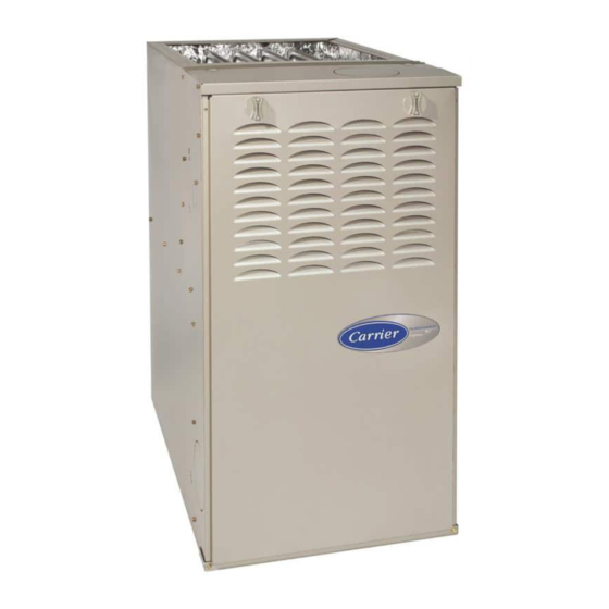
58PHA/PHX Performance Boost 80
4---Way Multipoise
Induced---Combustion Gas Furnace
Input Capacities: 45,000 thru 135,000 Btuh
Installation, Start---up, Operating and
. . . . . . . . . . . . . . . . . . . . . . . . . . . . . . . . . .
. . . . . . . . . . . . . . . . . . . . . . . . . . . . . . . . . . . . . . . .
. . . . . . . . . . . . . . . . . . . . . . . . . . . . . . .
. . . . . . . . . . . . . . . . . . . . . . . . . . . . . . . . . . .
. . . . . . . . . . . . . . . . . . . . . . . . . . . .
. . . . . . . . . . . . . . . . . . . . . . . . . . . . . . . . . . . . . . . .
. . . . . . . . . . . . . . . . . . . . . . . . . . . . . . . . . . . . .
. . . . . . . . . . . . . . . . . . . . . . . . . . . . . . . . . . . . . . .
. . . . . . . . . . . . . . . . . . . . . . . . . . . . . . . . . .
. . . . . . . . . . . . . . . . . . . . . . . . . . . . . .
. . . . . . . . . . . . . . . . . . . . . . . . . . .
. . . . . . . . . . . . . . . . . . . . . . . . . . .
. . . . . . . . . . . . . . . . . . . . . . . . . . . . . .
. . . . . . . . . . . . . . . . . . . . . . . . . . . . . . . . . . . . .
. . . . . . . . . . . . . . . . . . . . . . . . . . . . . . . . . . . .
. . . . . . . . . . . . . . . . . . . . . . . . . . . . . . . . . .
. . . . . . . . . . . . . . . . . . . . . . . . . . . . . . . . . . . . . . .
. . . . . . . . . . . . . . . . . . . . . . . . . . . . .
. . . . . . . . . . . . . . . . . . . . . . . . . . . . . . . . . . .
. . . . . . . . . . . . . . . . . . . . . . . . . . .
Service and Maintenance
Instructions Series 100/A
. . . . . . . . . . . . . . . . . . . . . . . .
. . . . . . . . . . . . . . . . . . . . . . . . . .
. . . . . . . . . . . . . . . . . . . . .
. . . . . . . . . . . . .
. . . . . . . . . . . . .
. . . . .
2
. . . . . . . . . . . . . . . . . . . . . . . . . . . . . . . . . . . . . .
3
4
4
5
5
5
5
5
5
5
5
6
10
10
11
13
14
14
17
NOTE: Read the entire instruction manual before starting the
22
installation.
36
Portions of the text and tables are reprinted from NFPA 54/ANSI
36
Z223.1- -2006E, with permission of National Fire Protection
36
Association, Quincy, MA 02269 and American Gas Association,
Washington DC 20001. This reprinted material is not the
36
complete and official position of the NFPA or ANSI on the
39
referenced subject, which is represented only by the standard in
its entirety.
. . . . . . . . . . . . . . . . . . . . . . . . . . . . . . . . . . .
. . . . . . . . . . . . . . . . . . . . . . . . . . .
. . . . . . . . . . . . . . . . . . . . . . . . . . .
. . . . . . . . . . . . . . . . . . . . . . . . . . . . . . .
. . . . . . . . . . . . . . . . . . . . . . . . . . . . . . . .
ama
ISO 9001:2000
REGISTERED
40
. . . . . . .
43
43
46
49
51
51
CERTIFIED
Advertisement
Table of Contents

Related Manuals for Carrier 58PHA/PHX Installation, start-up, operating and


Summary of Contents for Carrier 58PHA/PHX Installation, start-up, operating and
-
Page 1: Table Of Contents
58PHA/PHX Performance Boost 80 4---Way Multipoise Induced---Combustion Gas Furnace Input Capacities: 45,000 thru 135,000 Btuh Installation, Start---up, Operating and Service and Maintenance Instructions Series 100/A SAFETY CONSIDERATIONS ......Checklist . -
Page 2: Safety Considerations
(733mm) (664mm) 28-7/8" 26-1/8" (FLUE COLLAR) (641mm) 25-1/4" 2-7/16" (62mm) 22-9/16" AIRFLOW 1-5/16" (573mm) (33mm) 19" 13/16" JUNCTION BOX 13/16" (483mm) (21mm) 1-1/8" LOCATION (21mm) 5-15/16" (29mm) OUTLE T 4-13/16" (135mm) (122mm) 1/2" DIA. K.O.THERMOSTAT (22mm) 9-5/8" WIRE ENTRY (13mm) 11/16"... -
Page 3: Introduction
instructions thoroughly and follow all warnings or cautions outside the space containing the furnace. See “Air Ducts” include in literature and attached to the unit. Consult local section. building codes, the current editions of the National Fuel Gas 8. A gas- -fired furnace for installation in a residential garage Code (NFGC) NFPA 54/ANSI Z223.1 and the National must be installed as specified in the warning box in the Electrical Code (NEC) NFPA 70. -
Page 4: Codes And Standards
A08471 Fig. 2 - - Clearances to Combustibles CODES AND STANDARDS Safety USA: National Fuel Gas Code (NFGC) NFPA Follow all national and local codes and standards in addition to 54- -2006/ANSI Z223.1- -2006 and the Installation Stan- these instructions. The installation must comply with regulations dards, Warm Air Heating and Air Conditioning Sys- of the serving gas supplier, local building, heating, plumbing, and tems ANSI/NFPA 90B... -
Page 5: General Installation
CANADA: CAN/CSA- -B149.1- -05 Parts 4, 5, and 6 Max 85ºF/ 29ºC Appendices A, B, E, and H. Electrical Connections US: National Electrical Code (NEC) ANSI/NFPA 70- -2008. CANADA: Canadian Electrical Code CSA C22.1. Venting US: NFGC NFPA 54 / ANSI Z223.1- -2006; Chapters 12 and 13. -
Page 6: Location
THE BLOWER IS LOCATED BELOW THE BURNER SECTION, AND CONDITIONED AIR IS DISCHARGED UPWARD. THE BLOWER IS LOCATED TO THE RIGHT OF THE BURNER SECTION, AND AIR CONDITIONED AIR IS DISCHARGED TO THE LEFT. THE BLOWER IS THE BLOWER IS LOCATED TO THE LEFT LOCATED ABOVE THE OF THE BURNER SECTION,... - Page 7 Masonry acid washing materials CAUTION All fuel- -burning equipment must be supplied with air for fuel combustion. Sufficient air must be provided to avoid negative PERSONAL INJURY AND/OR PROPERTY pressure in the equipment room or space. A positive seal must be DAMAGE HAZARD made between the furnace cabinet and the return- -air duct to prevent pulling air from the burner area and from draft safeguard...
- Page 8 Table 3 – Minimum Space volumes for 100% combustion, Ventilation, and Dilution from Indoors OTHER THAN FAN---ASSISTED TOTAL FAN---ASSISTED TOTAL (1,000’S BTUH GAS INPUT RATE (1,000’S BTUH GAS INPUT RATE) ACH* Space Volume (ft. 0.60 1,050 1,400 1,750 1,100 1,650 2,200 2,750 3,300...
- Page 9 a. One opening MUST commence within 12- -in. (300 mm) WARNING of the ceiling and the second opening MUST commence within 12- -in. (300 mm) of the floor. b. Size openings and ducts per Fig. 7 and Table 2. CARBON MONOXIDE POISONING HAZARD c.
-
Page 10: Installation
of at least 2 in. /1,000 Btuh (4,400 mm /kW) of total input rating of all gas appliances. 2. An attic or crawlspace may be considered a space that freely communicates with the outdoors provided there are adequate permanent ventilation openings directly to outdoors having free area of at least 1- -in. -
Page 11: Downflow Installation
5/ 16 ″ (8mm) (8mm) 5/ 16 ″ ″ (44mm) PLENUM OPENING ″ (44mm) FLOOR (8mm) OPENING ″ (8mm) 5/ 16 ″ (44mm) 3/ 4 ″ 3/ 4 ″ (44mm) A89014 A96283 Fig. 10 - - Leveling Legs Fig. 11 - - Floor and Plenum Opening Dimensions 4. - Page 12 FURNACE APPROVED COIL ASSEMBLY COIL BOX COMBUSTIBLE FLOORING SHEET METAL PLENUM FLOOR OPENING A08556 Fig. 13 - - Furnace, Plenum, and Coil Assembly or Coil Box Installed on a Combustible Floor...
-
Page 13: Horizontal Installation
Table 4 – Opening Dimensions - - In. (mm) FURNACE PLENUM OPENING FLOOR OPENING CASING APPLICATION WIDTH Upflow Applications on Combustible or Noncombustible Floor- 12--- 11/16 21--- 5/8 13--- 5/16 22--- 1/4 ing (KGASB subbase not required) (322) (549) (338) (565) Downflow Applications on Noncombustible Flooring (KGASB 12--- 9/16... -
Page 14: Filter Arrangement
3. Remove bottom closure panel. NOTE: Flexible connections should be used between ductwork and furnace to prevent transmission of vibration. Ductwork 4. Reinstall bottom filler panel and screws. Side Return Air passing through unconditioned space should be insulated and Inlet sealed to enhance system performance. - Page 15 UPFLOW DOWNFLOW HORIZONTAL 90° 90° 120° 120° 120° A02020 Fig. 14 - - Duct Flanges " (6mm) THREADED ROD 4 REQ. OUTER DOOR A S SEMBLY SECURE ANGLE IRON TO BOTTOM OF FURNACE WITH 3 #8 x " (19mm) SCREWS TYPICAL FOR 2 SUPPORTS 8"...
- Page 16 METHOD 2 USE (4) #8 x 3/4 (19 mm) SHEET METAL SCREWS FOR EACH STRAP. THE STRAPS SHOULD BE VERTICAL AGAINST THE FURNACE SIDES AND NOT PULL AWAY FROM THE FURNACE SIDES. METHOD 1 FOLD ALL STRAPS UNDER FURNACE AND SECURE WTH (4) #8 x 3/4 (19 mm) SHEET METAL SCREWS (2 SCREWS IN SIDE AND 2 SCREWS IN BOTTOM).
-
Page 17: Gas Piping
Return Air Connections WARNING WARNING FIRE OR EXPLOSION HAZARD FIRE HAZARD Failure to follow this warning could result in personal injury, death, and/or property damage. Failure to follow this warning could cause personal injury, death and/or property damage. If local codes allow the use of a flexible gas appliance connector, always use a new listed connector. - Page 18 Table 5 – Air Delivery - - CFM (With Filter)* RETURN---AIR EXTERNAL STATIC PRESSURE (In. wc) UNIT SIZE SPEED SUPPLY 1185 1145 1115 1075 1035 045---08/ Bottom or 024045 Side(s) --- --- 1625 1585 1535 1495 1460 1415 1365 1295 1220 1125 1405...
- Page 19 A02075 Fig. 18 - - Upflow Return Air Configurations and Restrictions A02163 Fig. 19 - - Downflow Return Air Configurations and Restrictions...
- Page 20 A02162 Fig. 20 - - Horizontal Return Air Configurations and Restrictions 2” (51mm) Street Elbow A08551 Fig. 21 - - Burner and Manifold...
- Page 21 Table 7 – Electrical Data OPERATING VOLTS--- UNIT MAX WIRE MAX FUSE/ VOLTAGE* FURNACE MAX UNIT MIN WIRE HERTZ--- AMPACITY# LENGTH CKT BKR (VOLTS) MODEL (AMPS) GAGE PHASE (AMPS) FT. (M) (AMPS) 045--- 08 / 024045 115--- 60--- 1 10.9 34 (10) 070--- 16 / 048070 115--- 60--- 1...
-
Page 22: 115- -V Wiring
ELECTRICAL CONNECTION TO J- -BOX CAUTION Field- -Supplied Electrical Box on Furnace J- -Box Bracket See Fig. 23. FURNACE MAY NOT OPERATE 1. Remove cover from furnace J- -Box. Failure to follow this caution may result in intermittent 2. Attach electrical box to furnace J- -Box bracket with at least furnace operation. - Page 23 5. Connect line voltage leads as shown in Fig. 25. 6. Reinstall cover to J- -Box. Do not pinch wires between cover and bracket. 24- -V WIRING Make field 24- -v connections at the 24- -v terminal strip. (See Fig. 23.) Connect terminal Y/Y2 as shown in Fig.
- Page 24 BLOWER OFF-DELAY TWINNING AND/OR COMPONENT TEST TERMINAL 24-V THERMOSTAT TERMINALS HUMIDIFIER TERMINAL (24-VAC 0.5 AMP. MAX) 3-AMP FUSE LED OPERATION & DIAGNOSTIC LIGHT HEAT TRANSFORMER 24-VAC CONNECTIONS COOL BLOWER SPEED SELECTION TERMINALS SPARE 2 SPARE 1 PL1-LOW VOLTAGE DRAIN HARNESS CONNECTOR 115-VAC (L2) NEUTRAL...
- Page 25 the local building codes, and furnace and vent manufacturers’ WARNING instructions. These furnaces are design- -certified as Category I furnaces in CARBON MONOXIDE POISONING HAZARD accordance with ANSI Z21.47- -2006/CSA 2.3- -2006 and operate with a non- -positive vent static pressure to minimize the potential Failure to follow the steps outlined below for each for vent gas leakage.
- Page 26 See notes 2,5,7, and 10 on the page following these figures. See notes 1, 2, 4, 6, 7, 9, 10 and 12 on the page following these figures. A04215 A04217 Fig. 26 - - Single- -Stage Furnace with Single- -Speed Air Con- Fig.
- Page 27 HUMIDFIER HUMIDFIER (24VAC) (24VAC) See notes 1, 2, 4, 11, 12, and 13 on the page following these figures. See notes 1, 2, 3, 4, 11, 12, and 14 on the page following these figures. A04220 A04219 Fig. 31 - - Dual Fuel Thermostat with Single- -Stage Furnace Fig.
- Page 28 Canada (and U.S.A.)- -This furnace is permitted to be vented into Table 9 – Minimum Allowable Input Rating of Space- -Heat- a clay tile- -lined masonry chimney that is exposed to the outdoors ing Appliance in Thousands of BTUH per Hour below the roof line, provided: INTERNAL AREA OF CHIMNEY 1.
- Page 29 CHIMNEY INSPECTION CHART For additional requirements refer to the National Fuel Gas Code NFPA 54/ANSI Z223.1 and ANSI/NFPA 211 Chimneys, Fireplaces, Vents, and Solid Fuel Burning Appliances in the U.S.A. or to the Canadian installation Code CSA-B149.1 in Canada. Crown Rebuild condition: crown.
- Page 30 To prevent condensation in the furnace and vent system, the CAUTION following precautions must be observed: 1. The return- -air temperature must be at least 60_F CUT HAZARD (16_C)db except for brief periods of time during warm- -up from setback at no lower than 55_F (13_C) db or during Failure to follow this caution may result in personal injury.
- Page 31 SEE NOTES: 1,2,4,7,8,9 SEE NOTES:1,2,3,4,5,7,8,9 on the page following on the page following these figures these figures A03208 A03210 Fig. 34 - - Upflow Application- -Vent Elbow Up Fig. 36 - - Downflow Application- -Vent Elbow Up then Left SEE NOTES: 1,2,4,5,7,8,9 SEE NOTES: 1,2,3,4,7,8,9 on the page following on the pages following...
- Page 32 SEE NOTES: 1,2,4,7,8,9 on the page following these figures SEE NOTES: 1,2,4,5,6,7,8,9 on the page following these figures A03207 A03213 Fig. 38 - - Downflow Application- -Vent Elbow Left then Up Fig. 40 - - Horizontal Left Application- -Vent Elbow Left SEE NOTES: 1,2,4,5,7,8,9 on the page following these figures SEE NOTES:1,2,3,4,5,7,8,9...
- Page 33 SEE NOTES: 1,2,4,7,8,9 on the page following these figures SEE NOTES: 1,2,4,5,7,8,9 on the page following these figures A03214 A03219 Fig. 42 - - Horizontal Right Application- -Vent Elbow Right Fig. 44 - - Horizontal Right Application- -Vent Elbow Left then Up SEE NOTES: 1,2,4,5,7,8,9 on the page SEE NOTES: 1,2,4,5,7,8,9 on the page...
- Page 34 Venting Notes for Figures 34- -46 1. For common vent, vent connector sizing and vent 6. Accessory Downflow Vent Guard Kit, KGAVG0101DFG material: United States- -- -use the NFGC Canada- -- -use the required in downflow installations with lower vent CAN/CSA- -B149.1- -05 configuration.
- Page 35 A04128 A04130 Fig. 48 - - Rounded End of Knockout Fig. 50 - - Hammer and Screwdriver Used for Knockout A04129 A04131 Fig. 49 - - Knockout Pulled Loose Fig. 51 - - Remove Knockout with Hammer...
-
Page 36: Start- -Up, Adjustment, And Safety Check
START- -UP, ADJUSTMENT, AND SAFETY WARNING CHECK General ELECTRICAL SHOCK HAZARD Failure to follow this warning could result in personal WARNING injury, or death. Blower access door switch opens 115- -v power to control. FIRE HAZARD No component operation can occur unless switch is closed. Caution must be taken when manually closing this switch Failure to follow this warning could result in personal injury, death and/or property damage. - Page 37 The input rating for altitudes above 2,000 ft. (610 M) must adjustment tables. All models in all positions, except Low be reduced by 4 percent for each 1,000 ft. (305 M) above NOx models in downflow or horizontal positions, use sea level.
- Page 38 c. Measure time (in sec) for gas meter to complete 1 revolution and note reading. The 2 or 5 cubic feet dial provides a more accurate measurement of gas flow. d. Refer to Table 12 for cubic ft. of gas per hr. e.
-
Page 39: Check Safety Controls
Table 11 – Speed Selection THERMOSTAT SUBBASE TERMINALS WITH COLOR SPEED AS SHIPPED THERMOSTAT REMOVED Gray COOL (ANITICIPATOR, CLOCK, ETC., MUST BE OUT OF CIRCUIT.) Yellow SPARE Blue HEAT HOOK-AROUND AMMETER Orange SPARE CONT FAN * Continuous---blower speed---as shipped default R Y W G CAUTION FURNACE OVERHEATING HAZARD... -
Page 40: Checklist
Table 12 – Gas Rate (Cu Ft./Hr.) SIZE OF TEST DIAL SIZE OF TEST DIAL SECONDS SECONDS FOR 1 REVOLUTION FOR 1 REVOLUTION 2 Cu Ft. 5 Cu Ft. 1 Cu Ft. 2 Cu Ft. 5 Cu Ft. Cu Ft. 1800 1636 1500... - Page 41 Table 13 – Orifice Size* and Manifold Pressure (In. wc) for Gas Input Rate A08220...
- Page 42 Table 13 - - Orifice Size* and Manifold Pressure (In. wc) for Gas Input Rate (CONT) A08220A...
-
Page 43: Service And Maintenance Procedures
SERVICE AND MAINTENANCE PROCEDURES The electrical ground and polarity for 115- -v wiring must be WARNING properly maintained. Refer to Fig. 25 for field wiring information and to Fig. 59 for furnace wiring information. FIRE, INJURY, OR DEATH HAZARD NOTE: If the polarity is not correct, the STATUS LED on the control will flash rapidly and prevent the furnace from heating. - Page 44 Table 14 – Orifice Size* And Manifold Pressure (In. wc) For Gas Input Rate A08221...
-
Page 45: Component Test
Table 14- - Orifice Size* And Manifold Pressure (In. wc) For Gas Input Rate (CONT) A08221A SERVICE If status code recall is needed, briefly remove then reconnect one main limit wire to display stored status code. On RED LED boards do not remove power or blower door before initiating status code recall. After status code recall is completed component test will occur. -
Page 46: Care And Maintenance
CARE AND MAINTENANCE 4. Inspect burner compartment before each heating season for rust, corrosion, soot or excessive dust. If necessary, WARNING have furnace and burner serviced by a qualified service agency. 5. Inspect the vent pipe/vent system before each heating FIRE OR EXPLOSION HAZARD season for rust, corrosion, water leakage, sagging pipes or Failure to follow this warning could result in personal... - Page 47 NOTE: The blower wheel should not be dropped or bent as CAUTION balance will be affected. The following steps should be performed by a qualified service agency. UNIT DAMAGE HAZARD To ensure long life and high efficiency, clean accumulated dirt and grease from blower wheel and motor annually.
- Page 48 them thoroughly. A heavy build- -up of soot and carbon indicates 9/32” that a problem exists which needs to be corrected, such as 7.1mm improper adjustment of manifold pressure, insufficient or poor 5/16” quality combustion air, incorrect size or damaged manifold 7.9mm orifice( s), improper gas, or a restricted heat exchanger.
-
Page 49: Sequence Of Operation
hydrocarbons or inadequate seal may occur) and RTV sealant sequence of operation through the different modes. Read and (G.E. 162, 6702, or Dow- -Corning 738) are needed before follow the wiring diagram very carefully. starting installation. DO NOT substitute any other type of RTV NOTE: If a power interruption occurs during a call for heat (W), sealant. - Page 50 2. Cooling Mode c. When the “call for cooling” is satisfied and there is a The thermostat “calls for cooling.” demand for dehumidification, the cooling blower- -off delay is decreased from 90 seconds to 5 seconds. a. Single- -Speed Cooling (See Fig.
-
Page 51: Wiring Diagrams
5. Heat pump turn on the blower motor BLWM at HEAT speed, and (See Fig. 25 - - 32 for thermostat connections.) When begin a heating cycle. The blower motor BLWM will installed with a heat pump, the furnace control remain on until the end of the prepurge period, then shut automatically changes the timing sequence to avoid long off for 24 seconds then come back on at HEAT speed. - Page 52 A08176 Fig. 59 - - Wiring Diagram...
- Page 53 A02106A Fig. 60 - - Troubleshooting Guide...
- Page 54 Catalog No: 58PHA ---03SI Printed in U.S.A. Edition Date: 11/08 Copyright 2008 Carrier Corp. S 7310 W. Morris St. S Indianapolis, IN 46231 Replaces: 58PHA- -02SI Manufacturer reserves the right to change, at any time, specifications and designs without notice and without obligations.
Need help?
Do you have a question about the 58PHA/PHX Installation, start-up, operating and and is the answer not in the manual?
Questions and answers